Yamaha WaveRunner, Service Manual
The IBM WaveRunner manual is available for free download on our website. This comprehensive user manual provides detailed instructions on how to maximize the performance of your IBM WaveRunner device. Simply visit manualshive.com to download your manual and unlock the full potential of your product.
Share
Download


Reviews:
No comments
Related manuals for WaveRunner
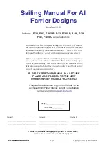
F-22
Brand: FARRIER MARINE Pages: 52
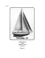
37
Brand: Tayana Pages: 85
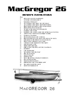
26
Brand: MACGREGOR Pages: 22
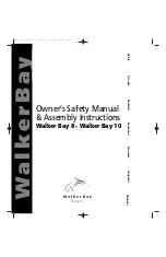
8
Brand: Walker Bay Pages: 16
110
Brand: J Pages: 30
42
Brand: Lagoon Pages: 122
64
Brand: Jeanneau Pages: 80
380
Brand: Lagoon Pages: 114
3500
Brand: Tartan Pages: 42
Express
Brand: Malibukayaks Pages: 19
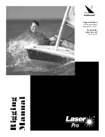
Laser Pro
Brand: Vanguard Sailboats Pages: 8

Sport
Brand: TAKACAT Pages: 12
Fun
Brand: Jeanneau Pages: 15
RX1
Brand: NEILPRYDE Pages: 4
F18
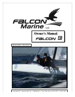
Brand: Falcon Pages: 41

Heron
Brand: Feathercraft Pages: 23
Wisper
Brand: Feathercraft Pages: 23
53
Brand: Jeanneau Pages: 58


