background image

101

QL5/QL1

 JK Circuit Board

to

 DSP32-CN751 (QL5)

to

 DSP1

6-CN751 (QL1)

Component side

(部品側)

2NA-WY63490 

1


Summary of Contents for QL5

Page 1: ...101 QL5 QL1 JK Circuit Board to DSP32 CN751 QL5 to DSP16 CN751 QL1 Component side 2NA WY63490 1...

Page 2: ...t Board ENC PNCOM Circuit Board LCDC 2NA WY93730 1 ENC 2NA ZF60470 1 WR 63 1 4 WR 63 1 4 WR 0 1 3 Q WR 0 1 3LQ WR 81 7 1 WR 81 7 3 QRW QVWD HG WR 81 7 1 3LQ WR 384 1 3LQ 2 3 1 4 WR 31 0 1 Component si...

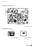
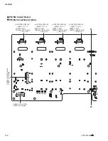
Page 3: ...103 QL5 QL1 PNL PNCOM Circuit Board 2NA ZF60470 1 WR 31 0 1 Component side Pattern side...

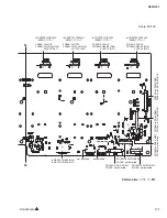
Page 4: ...QL5 QL1 104 2NA ZF60450 1 PN16M Circuit Board PN16S Circuit Board QL5 F F...

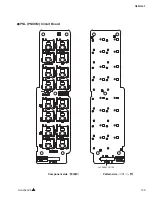
Page 5: ...105 QL5 QL1 Component side 2NA ZF60450 1 Scale 90 100 F F...

Page 6: ...installed to CRYSTAL DISPLAY to CRYSTAL DISPLAY to CRYSTAL DISPLAY to CRYSTAL DISPLAY PN16S CH1 2 PN16M CH17 18 QL5 CH1 2 QL1 PN16S CH3 4 PN16M CH19 20 QL5 CH3 4 QL1 PN16S CH5 6 PN16M CH21 22 QL5 CH5...

Page 7: ...to ENC CN401 PN16S not installed to DSP32 CN603 QL5 to DSP16 CN603 QL1 PN16M to PN2 CN302 PN16S to PN16M CN501 not installed not installed to CRYSTAL DISPLAY to CRYSTAL DISPLAY to CRYSTAL DISPLAY to C...

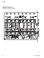
Page 8: ...QL5 QL1 108 PNR PNCOM Circuit Board 2NA ZF60470 1 Component side...

Page 9: ...109 QL5 QL1 PNR PNCOM Circuit Board 2NA ZF60470 1 WR 31 0 1 WR 31 0 1 Pattern side...

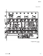
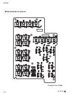
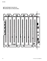
Page 10: ...QL5 QL1 110 FD1M FDCOM Circuit Board FD2 FDCOM Circuit Board QL5 FD1M FD2 2NA ZK68030 H H...

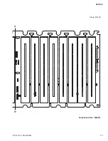
Page 11: ...111 QL5 QL1 FD1M FD2 2NA ZK68030 H H Component side Scale 90 100...

Page 12: ...QL5 QL1 112 FD1M FDCOM Circuit Board FD2 FDCOM Circuit Board QL5 0 WR 31 0 1 WR 31 6 1 0 WR 6 1 1 0 WR 63 1 4 WR 63 1 4 WR 63 1 0 WR 0 1 WR 0 1 I I FD1M FD2 2NA ZK68030...

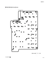
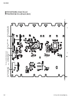
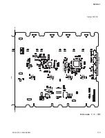
Page 13: ...113 QL5 QL1 Pattern side Scale 90 100 not installed I I FD1M FD2 2NA ZK68030...

Page 14: ...QL5 QL1 114 Pattern side Component side FD1S FDCOM Circuit Board WR 6 1 2NA ZK68030...

Page 15: ...attern side Component side Component side PN2 PNCOM Circuit Board USB LCDCOM Circuit Board PN2 2NA ZF60470 1 USB 2NA WY93730 1 to PN16M CN506 to PN16M CN301 to CRYSTAL DISPLAY MASTER A B WR 63 1 4 WR...

Page 16: ...ation 1 1 Measuring Instruments Use measuring instruments which can measure the inspection items accurately with confidence Input impedance of the measuring device should be 100 k or more System Two M...

Page 17: ...irm the range of difference in the gain measured in item 1 above as follows 6 Crosstalk between adjacent channels Parameters Turn on OMNI OUT of only one odd number channel for output turn off OMNI OU...

Page 18: ...of the permissible range 3 Distortion DIGITAL OUT 3 2 PLL Operating Range of WORD CLOCK IN Parameters Use the System Two When measuring L channel QL5 Use OMNI OUT 15 L QL1 Use OMNI OUT 7 L When measu...

Page 19: ...ic signals into DANTE input and listen to output from PHONES OUT To put music signals into DANTE input use Cubase For the details refer to DANTE sound output check on page 170 INSPECTIONS Recall scene...

Page 20: ...ut Judgment criteria 2 Confi rm that the output is free from noise In the same manner recall scenes 6 through 36 and check by listening The scene numbers and EFFECT types are as follows e DANTE input...

Page 21: ...8 1 3 YSISS USB 1 LCD SET UP SETUP 2 FIRMWARE 154 1 4 B SEL INITIALIZE ALL MEMORIES 156 1 5 160 1 6 CH NAME LCD 163 1 7 CPUQL MRAM ON LCD Memory Error Current Memories were Initialized 2 ANALOG IN OU...

Page 22: ...UT 1 XLR 2 3 2 1 10 k 48 ON 48 OFF 2 2 QL5 INPUT 17 32 OMNI OUT 1 16 QL1 INPUT 9 16 OMNI OUT 1 8 QL5 CH 17 32 INPUT XLR CH 17 32 CH 17 32 OMNI OUT 1 16 QL1 CH 9 16 INPUT XLR CH 9 16 CH 9 16 OMNI OUT 1...

Page 23: ...OUT System Two INPUT 1 A WORD CLOCK INT48 kHz WORD CLOCK INT48 kHz DIGITAL OUT f DIGITAL OUT 1 kHz DIGITAL OUT 3 2 WORD CLOCK IN PLL System Two Lch QL5 OMNI OUT 15 L QL1 OMNI OUT 7 L Rch QL5 OMNI OUT...

Page 24: ...Hz WORD CLOCK IN 50 kHz Device Config Sample Rate Sample Rate 48 k Pull up down 4 1667 WORD CLOCK IN B 44 1 kHz 4 42 336 kHz WORD CLOCK IN 42 336 kHz Device Config Sample Rate Sample Rate 44 k Pull up...

Page 25: ...ynamic Filter 21 5 Reverb 22 5 Symphonic 23 5 HQ Pitch 24 5 Dynamic Filter 25 6 Reverb 26 6 Symphonic 27 6 Dual Pitch 28 6 Dynamic Filter 29 7 Reverb 30 7 Symphonic 31 7 HQ Pitch 32 7 Dynamic Filter 3...

Page 26: ...608 D 1 pc Service check for PC application Load the latest program shown in the following table into QL5 QL1 itself and PC before executing the service check For the updating procedure refer to the U...

Page 27: ...net Mask and Default Gate Way that are identical with those of QL Setting Network IP address 192 168 0 1 Sub net mask 255 255 255 0 Default gateway 192 168 0 1 Confirming Setting Time Date Open Time D...

Page 28: ...iagram for checking SLOT 1 SLOT2 WORD CLOCK OUT WORD CLOCK IN PC IN OUT b QL5 QL1 DSP32 DNT5 DNT1 JK OUT OUTPUT INPUT b OUTPUT QL5 DSP16 QL1 JIG mode 1 3 Connection Rio3224 D Test jig Set the DIP swit...

Page 29: ...1 1 15 DM9000 Set the network with DM9000 and check if it is linked with the internal switch on the Dante circuit board Auto 1 16 USB STORAGE Check control line by reading writing USB MEMORY Auto 1 17...

Page 30: ...he power supply while pressing the QL USER DEFINED KEYS 1 2 and 3 at the same time Start up the PC application after starting the QL diagnosis and waiting for about 30 seconds When checking the FADER...

Page 31: ...an 2 8 V NG x xxV BATT Low Voltage is lower than specified value 2 8 V to less than 3 5 V OK x xxV Voltage Indication in the right window Remarks Less than 2 2 V OK x xxV BATT Low 2 2 V or more NG x x...

Page 32: ...Bus MPR OK 9 SIO Connection OK DSP6 DSP6 SIO test A PIO Connection OK DSP6 DSP6 SIO test 1 4 RTC test Contents Obtains and sets Real Time Clock Example of executing screen The automatic check AUTO is...

Page 33: ...Checks the FLAG line between CPU and SHARC Example of executing screen 1 9 SLOT Test Contents Checks the power voltage supplied to each interface and SLOT of MY SLOT 2SLOT check Example of executing s...

Page 34: ...re the same Refer to the 128 page for a connection method Example of executing screen 1 10 WORD CLOCK Test Contents Checks WORD CLOCK OUT IN automatically by counting it at PLLPU Fs 44 1 48 kHz Checks...

Page 35: ...is lighted and then select YES When the dialog box appears as shown below confirm that the LAMP is turned off and then select YES 1 13 GPI Test Contents Checks with OUT and IN connected with a jig Exa...

Page 36: ...in gradation from the right to left growing into black Check that the colors 5 x 4 other than black are displayed in gradation properly 1 18 LCD Test Contents LCD display test Among patterns of the L...

Page 37: ...er by pressing the B SEL key select TOUCH SCREEN CALIBRATION from MENU and press 4 corners of the square sequentially As a cross cursor appears check that its position is the same as the pressed posit...

Page 38: ...versed contrast as described below during the normal operation check or sound output check While viewing the NAME DISPLAY at the height barely visible from the front pad adjust the contrast close to t...

Page 39: ...reaction may be delayed as the reset in DANTE may take a while As this is repeated once every ten over seconds depending on the differences of the DANTE module the symptom will no longer appear if th...

Page 40: ...EBU 1 BNC Word Clock 1 MIDI 1 USB 1 LAMP 1 GPI 1 Rio3224 D Rio1608 D 1 PC QL5 QL1 PC 154 FIRMWARE YSISS QL Firmware v1 02f FILE MAIN FIRMWARE MQLP1 02 PGM V1 02 CPU USB PC TestProgram Factory Test PC...

Page 41: ...er Device No 1 Device Name Device ID 1 TCP KEEPALIVE on IP Address Protect No QL SETUP IP Address MAC Address LAN Internet 1 2 Ethernet Windows 7 TCP IP QL SETUP NETWORK IP Address Subnet Mask IP QL I...

Page 42: ...Y16 EX jig LAN UTP CAT 5 straight cable LAN UTP CAT 5 straight cable XLR Cable XLR Cable PRIMARY LAN UTP CAT 5 straight cable SW104 is set to JIG audio precision system2 AES EBS D A D SUB DA 15 MALE J...

Page 43: ...OT2 SLOT 1 10 WORD CLOCK WCLK OUT Fs WCLK IN PLL LOCK 1 11 AES EBU OUT SYSTEM2 1 12 MIDI MIDI IN OUT LoopBack 1 13 GPI IN OUT 1 14 NETWORK PC 1 1 15 DM9000 DM9000 Dante 1 16 USB STORAGE USB MEMORY W R...

Page 44: ...QL5 QL1 144 QL5 2 QL 1 QL QL USER DEFINED KEYS 1 2 3 PC QL 30 160 NG 2 PC PC Windows DiagQL5 service exe DiagQL1 service exe A A PC 188...

Page 45: ...00 MAC Address MAC Address 00 A0 DE 25 16 25 DM9000 MAC Address MAC 00 A0 DE 25 16 26 Brooklyn2 Version Firm 3 4 3 8 Soft3 6 4 20 Ymh 1 1 3 0 tx 64ch rx 64ch Brooklyn2 MAC Address Pri 00 1D C1 06 5A D...

Page 46: ...Bus OK 5 CPU Interface BUS W R Reg OK 6 DRAM Interface Data Bus OK 7 DRAM Interface Address Bus OK 8 DRAM Interface Address Bus MPR OK 9 SIO Connection OK DSP6 DSP6 SIO test A PIO Connection OK DSP6...

Page 47: ...0000 X00X MSB LSB IC DSP X 2 SIO Connection DSP7 DSP6 NG 1 ICxxx 1 Soxx ICxxx 1 Sixx 1 8 SHARC Test CPU SHARC SHARC SDRAM Address Bus Data Bus CPU SHARC FLAG 1 9 SLOT Test MY SLOT SLOT 2SLOT SLOT1 SLO...

Page 48: ...ES EBU OUT test 142 1 KHz OK NG 1 12 MIDI test MIDI 142 1 10 WORD CLOCK Test WORD CLOCK OUT IN PLLPU Fs 44 1 48kHz PLL LOCK Fs 200ms UNLOCK Read PLL LOCK Fs FPGA Internal Clock Fs 44 1 kHz 48 kHz UNLO...

Page 49: ...QL5 QL1 149 1 16 USB STORAGE test USB USB USB STRAGE 1 17 LAMP test LAMP LAMP YES LAMP YES 1 13 GPI Test OUT IN 1 14 NETWORK Test PC OK 1 15 DM9000 test DSP32 16 DM9000 Dante...

Page 50: ...QL5 QL1 150 2 H 3 O X O 4 BOX 5x4 1 18 LCD Test LCD LCD 1 3 2 9 5 OK NG 1...

Page 51: ...RECORDER IC MP3 Decoder Encoder R e g i s t e r W r i t e R e a d D a t a B U S AddressBUS DSP7 SIO DSP7 SH7724 CPU NG 1 CPU Interface Data Bus NG IC402 0000 XXXX 0000 0000 0000 X00X X MSB LSB 2 SIO C...

Page 52: ...t Brooklyn2 Brooklyn2 Ethernet 1 22 DNT SIO Test DSP7 DANTE DNT Brooklyn UART SPI Primary Secondary LED LED 2 PC 2 0 CH NAME LCD MiniLCD NAME DISPLAY NAME DISPLAY NAME DISPLAY NG 2 1 LED CH NAME LCD L...

Page 53: ...ORT REDUNDANT DIAG 2 4 LED LED LED LED LED LED CH METER GAIN CH30 QL5 CH14 QL1 6 PAN CH30 QL5 CH14 QL1 12 HPF CH31 QL5 CH15 QL1 18 DYNAMICS 1 CH32 QL5 CH16 QL1 6 DYNAMICS 2 CH32 QL5 CH16 QL1 12 EQUALI...

Page 54: ...d the main program is activated automatically After confirming that turn off the power switch and disconnect the USB memory If the power is turned on again after updating the PROGRAM the INITIALIZE sc...

Page 55: ...ITIALIZE CURRENT MEMORIES INITIALIZATION To reset settings to the factory shipment state execute forced initialization by turning on the power switch while holding down the A SEL and B SEL keys simult...

Page 56: ...S B SEL 3 MRAM FLASH ROM CURRENT SCENE SETUP DATA PORT TRIM DIO SCENE1 300 DATA LIBRARY DATA FADER CALIBRATION INITIALIZE ALL MEMORIES INITIALIZE CURRENT MEMORIES FLASH ROM NAME BL CALIBRATION CH COLO...

Page 57: ...touch screen window will appear Then touch the START button If the above window does not appear press the FADER BANK B1 B2 key to select TOUCH SCREEN CALIBRATION and press the B4 key to start 3 As a...

Page 58: ...QL5 QL1 158 1 B SEL INITIALIZE TRIM CALIBRATION 2 MODE SELECT TOUCH SCREEN CALIBRATION START FADER BANK B1 B2 TOUCH SCREEN CALIBRATION B4 3 OK 4 3...

Page 59: ...ders to the top and execute NEXT 9 As Calibrating the Faders appears on the screen and the motor driven calibration is started do not touch the faders until it is completed 10 When the motor driven ca...

Page 60: ...O dB and Press NEXT Button NEXT 6 MOVE ALL SELECTED FADERS TO 20dB and Press NEXT Button 20 NEXT 7 MOVE ALL SELECTED FADERS TO 0dB and Press NEXT Button 0 NEXT 8 MOVE ALL SELECTED FADERS TO 10dB and P...

Page 61: ...e not found 5 As the final step press the APPLY key to store the adjusted values When simultaneously holding down the 32 SEL key and the B SEL key for QL5 or the 16 SEL key and the B SEL key for QL1 w...

Page 62: ...ith RESET ALL If you simply press the B SEL key during this operation the values will be those that were last set with APPLY with RESET ALL CH NAME LCD back light adjustment 1 Adjust the brightness of...

Page 63: ...2 Ch SEL Key Ch 3 C e n t r a l L o g i c R G B A D J U S T M E N T TOUCH AND TURN RGB ADJUSTMENT 1ch Red Green Blue Red Green Blue 4 5 APPLY QL5 32 SEL B SEL QL1 16 SEL B SEL RESET ALL LED 6 CH NAME...

Page 64: ...3 Gray4 2 4 APPLY QL5 32 SEL B SEL QL1 16 SEL B SEL RESET ALL LED CH NAME LCD CH NAME LCD QL5 32 SEL B SEL QL1 16 SEL B SEL RESET ALL CH NAME LCD B SEL RESET ALL APPLY CH NAME LCD 1 CUE ON CH CH CUE...

Page 65: ...m of the screen and returns to the normal mode Same as when the power is restarted 1 SETUP SETUP Capture Mode 2 USB USB 3 USER DEFINED KEY 1 4 USB 5 SETUP Normal Mode USB OVER CURRENT SAVE LOAD FORMAT...

Page 66: ...ger Dante Firmware Update Manager Immediately after starting the screen is as shown below The interface selection screen may appear depending on your PC In that case select the interface to be connect...

Page 67: ...is as shown below Updating 1 1 is indicated in the Status column 6 Completion of updating When updating is over a popup confirming it will appear Press the OK button and the screen display will be as...

Page 68: ...rmwareUpdateManager exe Bonjour 3 QL Primary Ethernet CAT5e 1 QL 2 Audinate Firmware Update Manager DANTE Audinate Dante Firmware Update Manager Dante Firmware Update Manager PC Dante Update Dante Fir...

Page 69: ...QL5 QL1 169 5 Start QL OK Status Updating 1 1 6 OK Status Update Done 7 Status Error QL...

Page 70: ...ly as follows 7 Return to the beginning by using the button of Cubase and press the red round button for sound reproduction Refer to the figure below the button is also usable for sound reproduction c...

Page 71: ...rogram Existing tracks can be copied and pasted or dragged and dropped from the Pool window The length of the test is 8 minutes when the tracks are played and no sound will be heard in the latter half...

Page 72: ...Primary PC Ether 2 QL MIDI IN PC USB UX16 3 AllData SEISAN1 CLF 4 Cubase DSP6 5 Dante Virtual Sound Setting ON 6 Dante Contoroller File Load Preset Dante DSP6 preset Patch ON 7 Cubase Cubase 5 38 37 M...

Page 73: ...QL5 QL1 173 CD CD Ctrl Audio CD wav OK 01 01 Ctrl P 8 8 8 8 m ON ON OVER 10 00 dB 0 00 dB...

Page 74: ...nt or C MD1 bin file present BUS Initial Settings SysKernel Cancel I2C P BUS Reset cancel E BUS Reset E BUS driver initialization and E BUS START I2C driver initialization and P BUS START Check if the...

Page 75: ...CA Control Invalid OK OK OK EXIT NG NG NG 2 5V or lower or checksum error Maintenance Boot menu screen displayed LCD Display ERROR pop up displayed Maintenance Boot menu screen displayed LCD Display F...

Page 76: ...ne No No No No No No 2 1 3 Character string stored in the specific areas at 2 locations in MRAM is obtained Memory initialization is executed MRAM NG flag TRUE Maintenance screen displayed Various err...

Page 77: ...llowing criteria The voltage is measured at 1 minute intervals 2 5V or lower NO Battery backup not possible 2 8V or lower LOW Time to replace battery 3 5V or lower OK Normal 3 Even when the unit is st...

Page 78: ...r Main Program PLL ROM SDRAM SysKernel Start Kernel PGM C MD1 bin BUS SysKernel I2C P BUS Reset E BUS Reset E BUS E BUS START I2C P BUS START Panel SysKernel MRAM SysKernel Current Memory MRAM Current...

Page 79: ...rnel SysKernel DANTE MUTE DIO DANTE MUTE DIO Brooklyn2 Network DANTE MUTE fs 500mS DIO Brooklyn2 BCA Control OK OK OK EXIT NG NG NG 2 5V LCD Display ERROR LCD Display or 2 5V 2 8V CAUTION SysKernel Me...

Page 80: ...QL5 QL1 180 O MRAM MRAM No No No No No No 2 1 3 MRAM 2 MRAM NG TRUE Popup Exit MacAddress NG TRUE Fader NG TRUE LowBattery Popup MacAddress NG Fader FALSE 2 5V...

Page 81: ...net MemoryError Memory Error All Memories Initialized LowBattery Low Battery Initialize AllMemories Fader NG FaderCalibration 2 SETUP 1 2 5V NO 2 8V LOW 3 5V OK 3 Low Battery Popup Low Battery Popup O...

Page 82: ...X X Start while pressing A_SEL and B_SEL keys O O X X X X O X X Automatically initialized along with a change in the memory structure X X X X X X X X X Automatically initialized when started due to M...

Page 83: ...Cannel Color Calibration Channel Name Backlight Calibration User Bitmap Mac B SEL LCD INITIALIZE ALL MEMORIES B SEL LCD INITIALIZE CURRENT MEMORIES A SEL B SEL MRAM Initialization applicability MRAM C...

Page 84: ...re not selected select either DiagQL5_service exe or DiagQL1_service exe 2 Confirm that there are checks on all of the items to be tested in the list window If all of the items to be tested do not hav...

Page 85: ...cceeded Inspection was NG Object to be inspected is displayed r IFDL CPY XJUI UJDL JT SFHBSEFE BT PCKFDU UP CF inspected r CMF UP QFSGPSN 6OJU JOTQFDUJPO CZ TFMFDUJOH JOEJWJEVBMMZ r FUBJMFE JOTQFDUJPO...

Page 86: ...up Moves to the folder just abo ve the current folder Large Icons Displays items with large icons Small Icons Displays items with small icons List Displays items as a list Details Displays items as a...

Page 87: ...changed with View Option menu With this window it is possible to switch between displayed hidden state and between floating docking state Displayed hidden state can be switched with View Options menu...

Page 88: ...service exe Windows DiagQL5 service exe DiagQL1 service exe DiagQL5 service exe 1 QL5 SERVICE 3 3 2 ALL ON 2 1 DiagQL5 service exe DiagQL1 service exe DiagQL5 service exe DiagQL1 service exe 2 All on...

Page 89: ...QL5 QL1 189 q w NG OK...

Page 90: ...utput Save log Exit Test Execute Start Pause Stop Clear result NG Stop NG Check All on All off Selected on Selected off NG on NG NG off NG Port setup View Folder up Large Icons Small Icons List Detail...

Page 91: ...QL5 QL1 191 y u i o F1 F12 0 Port Setting error Ethernet Network...

Page 92: ...l B British model C Canadian model D German model E European model F French model H North European model I Indonesian model J Japanese model K Korean model M South African model O Chinese model P Braz...

Page 93: ...140 140 170 180 170a 170c 150c 150d 150a 150b 170b 170d 130 130 SIDE PAD ASSEMBLY R Ass y R 150 160 SIDE PAD ASSEMBLY L Ass y L BOTTOM L ASSEMBLY See page 6 L Ass y CONTROL PANEL L ASSEMBLY See page 1...

Page 94: ...80 4 150c WE962000 BIND HEAD TAPPING SCREW B 4 0X8 MFZN2B3 4 01 150d YAMAHA LOGO PLATE M ZJ40930 160 ZH568700 MACHINE SCREW M5 0X18 MFZN2B3 3 170 ZJ291300 SIDE PAD ASSEMBLY R RIGHT 170a SIDE PAD R BLA...

Page 95: ...LY S QL1 120 120 30 10 20 180 130 130 160 170 160a 160c 140c 140d 140a 140b 160b 160d 120 120 140 150 27720 6 66 0 6HH SDJH 6 VV 6 3 66 0 5 R 6 3 66 0 L 21752 3 1 6 66 0 6HH SDJH 6 VV 110 40 80 50 90...

Page 96: ...LE ZJ21080 4 140c WE962000 BIND HEAD TAPPING SCREW B 4 0X8 MFZN2B3 4 01 140d YAMAHA LOGO PLATE M ZJ40930 150 ZH568700 MACHINE SCREW M5 0X18 MFZN2B3 3 160 ZJ291300 SIDE PAD ASSEMBLY R RIGHT 160a SIDE P...

Page 97: ...10 320 390 410 150 170 120 120 610 330 100 110 400 110 100 210 95 170 160 280 270 350 340 180 190 850 590 610 600 580 560 940 190 260 360 590 910 920 600 570 840 380 370 200 40 50 50 50 80 90 80 90 10...

Page 98: ...70 890 890 730 710 710 720 840 840 850 850 900 930 950 780 820 240 220 260 210 630 630 540 550 820 500 480 485 440 910 900 920 940 440 490 495 420 430 440 470 880 960 460 230 510 510 300 285 500 250 2...

Page 99: ...QL5 QL1 8 980 880 x16 820 x16 820 x16 230 x2 250 x2 630 x16 630 x16 880 x16 970 x4 300 x4 20e x4 510 x2 510 x2 460 x2 550 540 x4 500 x2 BOTTOM L ASSEMBLY L Ass y Assembly Outline View Rear view...

Page 100: ...QL5 QL1 9 20 20a 20c 20g 20b 20b 20d 20f 20e REAR L ASSEMBLY L Ass y JK SHEET ASSEMBLY JK Ass y 470 470a 470b Solder...

Reviews: