

MIXING CONSOLE
CONSOLES DE MIXAGE
MISCHPULTE
CONSOLA DE MEZCLA
User’s Guide
Manuel d’utilisation
Bedienungsanleitung
Manual de uso
24
A
B
20dB
GAIN
–16
–60
HIGH
–15
+15
MID FREQ
250
5K
MID
–15
+15
LOW
–15
+15
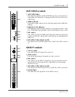
AUX 1
0
10
AUX 2
0
10
AUX 3
0
10
AUX 4
0
10
AUX 5
0
10
PAN
L
ODD
R
EVEN
∞
40
30
25
20
15
10
5
0
5
10
ON
PFL
ST
3–4
1–2
P
O
S
T
P
R
E
PRE
EQ
80
PEAK
SIGNAL
23
A
B
20dB
GAIN
–16
–60
HIGH
–15
+15
MID FREQ
250
5K
MID
–15
+15
LOW
–15
+15
AUX 1
0
10
AUX 2
0
10
AUX 3
0
10
AUX 4
0
10
AUX 5
0
10
PAN
L
ODD
R
EVEN
∞
40
30
25
20
15
10
5
0
5
10
ON
PFL
ST
3–4
1–2
P
O
S
T
P
R
E
PRE
EQ
80
PEAK
SIGNAL
22
A
B
20dB
GAIN
–16
–60
HIGH
–15
+15
MID FREQ
250
5K
MID
–15
+15
LOW
–15
+15
AUX 1
0
10
AUX 2
0
10
AUX 3
0
10
AUX 4
0
10
AUX 5
0
10
PAN
L
ODD
R
EVEN
∞
40
30
25
20
15
10
5
0
5
10
ON
PFL
ST
3–4
1–2
P
O
S
T
P
R
E
PRE
EQ
80
PEAK
SIGNAL
21
A
B
20dB
GAIN
–16
–60
HIGH
–15
+15
MID FREQ
250
5K
MID
–15
+15
LOW
–15
+15
AUX 1
0
10
AUX 2
0
10
AUX 3
0
10
AUX 4
0
10
AUX 5
0
10
PAN
L
ODD
R
EVEN
∞
40
30
25
20
15
10
5
0
5
10
ON
PFL
ST
3–4
1–2
P
O
S
T
P
R
E
PRE
EQ
80
PEAK
SIGNAL
20
A
B
20dB
GAIN
–16
–60
HIGH
–15
+15
MID FREQ
250
5K
MID
–15
+15
LOW
–15
+15
AUX 1
0
10
AUX 2
0
10
AUX 3
0
10
AUX 4
0
10
AUX 5
0
10
PAN
L
ODD
R
EVEN
∞
40
30
25
20
15
10
5
0
5
10
ON
PFL
ST
3–4
1–2
P
O
S
T
P
R
E
PRE
EQ
80
PEAK
SIGNAL
19
A
B
20dB
GAIN
–16
–60
HIGH
–15
+15
MID FREQ
250
5K
MID
–15
+15
LOW
–15
+15
AUX 1
0
10
AUX 2
0
10
AUX 3
0
10
AUX 4
0
10
AUX 5
0
10
PAN
L
ODD
R
EVEN
∞
40
30
25
20
15
10
5
0
5
10
ON
PFL
ST
3–4
1–2
P
O
S
T
P
R
E
PRE
EQ
80
PEAK
SIGNAL
18
A
B
20dB
GAIN
–16
–60
HIGH
–15
+15
MID FREQ
250
5K
MID
–15
+15
LOW
–15
+15
AUX 1
0
10
AUX 2
0
10
AUX 3
0
10
AUX 4
0
10
AUX 5
0
10
PAN
L
ODD
R
EVEN
∞
40
30
25
20
15
10
5
0
5
10
ON
PFL
ST
3–4
1–2
P
O
S
T
P
R
E
PRE
EQ
80
PEAK
SIGNAL
17
A
B
20dB
GAIN
–16
–60
HIGH
–15
+15
MID FREQ
250
5K
MID
–15
+15
LOW
–15
+15
AUX 1
0
10
AUX 2
0
10
AUX 3
0
10
AUX 4
0
10
AUX 5
0
10
PAN
L
ODD
R
EVEN
∞
40
30
25
20
15
10
5
0
5
10
ON
PFL
ST
3–4
1–2
P
O
S
T
P
R
E
PRE
EQ
80
PEAK
SIGNAL
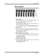
24
ST IN 1/3
S
T
1
A
B
+4
-10
PEAK
SIGNAL
HIGH
–15
+15
LOW
–15
+15
AUX 2
1–2
3–4
ST
AUX 1
BAL/PAN
L
ODD
R
EVEN
LEVEL
0
10
ON
PFL
S
T
3
+4
-10
PEAK
SIGNAL
HIGH
–15
+15
LOW
–15
+15
AUX 4
1–2
3–4
ST
AUX 3
BAL/PAN
L
ODD
R
EVEN
LEVEL
0
10
ON
PFL
ST IN 1/3
L
ODD
R
EVEN
ST IN 2/4
S
T
2
A
B
+4
-10
PEAK
SIGNAL
HIGH
–15
+15
LOW
–15
+15
AUX 2
1–2
3–4
ST
AUX 1
BAL/PAN
L
ODD
R
EVEN
LEVEL
0
10
ON
PFL
S
T
4
+4
-10
PEAK
SIGNAL
HIGH
–15
+15
LOW
–15
+15
AUX 4
1–2
3–4
ST
AUX 3
BAL/PAN
LEVEL
0
10
ON
PFL
ST IN 2/4
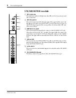
GROUP 1
GROUP 2
GROUP 3
GROUP 4
L
R
ST2/MONITOR
L
R
STEREO 1
METER SELECT
MIXING CONSOLE
23
22
21
20
19
18
17
16
A
B
20dB
GAIN
–16
–60
HIGH
–15
+15
MID FREQ
250
5K
MID
–15
+15
LOW
–15
+15
AUX 1
0
10
AUX 2
0
10
AUX 3
0
10
AUX 4
0
10
AUX 5
0
10
PAN
L
ODD
R
EVEN
∞
40
30
25
20
15
10
5
0
5
10
ON
PFL
ST
3–4
1–2
P
O
S
T
P
R
E
PRE
EQ
80
PEAK
SIGNAL
16
15
A
B
20dB
GAIN
–16
–60
HIGH
–15
+15
MID FREQ
250
5K
MID
–15
+15
LOW
–15
+15
AUX 1
0
10
AUX 2
0
10
AUX 3
0
10
AUX 4
0
10
AUX 5
0
10
PAN
L
ODD
R
EVEN
∞
40
30
25
20
15
10
5
0
5
10
ON
PFL
ST
3–4
1–2
P
O
S
T
P
R
E
PRE
EQ
80
PEAK
SIGNAL
15
14
A
B
20dB
GAIN
–16
–60
HIGH
–15
+15
MID FREQ
250
5K
MID
–15
+15
LOW
–15
+15
AUX 1
0
10
AUX 2
0
10
AUX 3
0
10
AUX 4
0
10
AUX 5
0
10
PAN
L
ODD
R
EVEN
∞
40
30
25
20
15
10
5
0
5
10
ON
PFL
ST
3–4
1–2
P
O
S
T
P
R
E
PRE
EQ
80
PEAK
SIGNAL
14
13
A
B
20dB
GAIN
–16
–60
HIGH
–15
+15
MID FREQ
250
5K
MID
–15
+15
LOW
–15
+15
AUX 1
0
10
AUX 2
0
10
AUX 3
0
10
AUX 4
0
10
AUX 5
0
10
PAN
L
ODD
R
EVEN
∞
40
30
25
20
15
10
5
0
5
10
ON
PFL
ST
3–4
1–2
P
O
S
T
P
R
E
PRE
EQ
80
PEAK
SIGNAL
13
12
A
B
20dB
GAIN
–16
–60
HIGH
–15
+15
MID FREQ
250
5K
MID
–15
+15
LOW
–15
+15
AUX 1
0
10
AUX 2
0
10
AUX 3
0
10
AUX 4
0
10
AUX 5
0
10
PAN
L
ODD
R
EVEN
∞
40
30
25
20
15
10
5
0
5
10
ON
PFL
ST
3–4
1–2
P
O
S
T
P
R
E
PRE
EQ
80
PEAK
SIGNAL
12
11
A
B
20dB
GAIN
–16
–60
HIGH
–15
+15
MID FREQ
250
5K
MID
–15
+15
LOW
–15
+15
AUX 1
0
10
AUX 2
0
10
AUX 3
0
10
AUX 4
0
10
AUX 5
0
10
PAN
L
ODD
R
EVEN
∞
40
30
25
20
15
10
5
0
5
10
ON
PFL
ST
3–4
1–2
P
O
S
T
P
R
E
PRE
EQ
80
PEAK
SIGNAL
11
10
A
B
20dB
GAIN
–16
–60
HIGH
–15
+15
MID FREQ
250
5K
MID
–15
+15
LOW
–15
+15
AUX 1
0
10
AUX 2
0
10
AUX 3
0
10
AUX 4
0
10
AUX 5
0
10
PAN
L
ODD
R
EVEN
∞
40
30
25
20
15
10
5
0
5
10
ON
PFL
ST
3–4
1–2
P
O
S
T
P
R
E
PRE
EQ
80
PEAK
SIGNAL
10
9
A
B
20dB
GAIN
–16
–60
HIGH
–15
+15
MID FREQ
250
5K
MID
–15
+15
LOW
–15
+15
AUX 1
0
10
AUX 2
0
10
AUX 3
0
10
AUX 4
0
10
AUX 5
0
10
PAN
L
ODD
R
EVEN
∞
40
30
25
20
15
10
5
0
5
10
ON
PFL
ST
3–4
1–2
P
O
S
T
P
R
E
PRE
EQ
80
PEAK
SIGNAL
9
8
A
B
20dB
GAIN
–16
–60
HIGH
–15
+15
MID FREQ
250
5K
MID
–15
+15
LOW
–15
+15
AUX 1
0
10
AUX 2
0
10
AUX 3
0
10
AUX 4
0
10
AUX 5
0
10
PAN
L
ODD
R
EVEN
∞
40
30
25
20
15
10
5
0
5
10
ON
PFL
ST
3–4
1–2
P
O
S
T
P
R
E
PRE
EQ
80
PEAK
SIGNAL
8
7
A
B
20dB
GAIN
–16
–60
HIGH
–15
+15
MID FREQ
250
5K
MID
–15
+15
LOW
–15
+15
AUX 1
0
10
AUX 2
0
10
AUX 3
0
10
AUX 4
0
10
AUX 5
0
10
PAN
L
ODD
R
EVEN
∞
40
30
25
20
15
10
5
0
5
10
ON
PFL
ST
3–4
1–2
P
O
S
T
P
R
E
PRE
EQ
80
PEAK
SIGNAL
7
6
A
B
20dB
GAIN
–16
–60
HIGH
–15
+15
MID FREQ
250
5K
MID
–15
+15
LOW
–15
+15
AUX 1
0
10
AUX 2
0
10
AUX 3
0
10
AUX 4
0
10
AUX 5
0
10
PAN
L
ODD
R
EVEN
∞
40
30
25
20
15
10
5
0
5
10
ON
PFL
ST
3–4
1–2
P
O
S
T
P
R
E
PRE
EQ
80
PEAK
SIGNAL
6
5
A
B
20dB
GAIN
–16
–60
HIGH
–15
+15
MID FREQ
250
5K
MID
–15
+15
LOW
–15
+15
AUX 1
0
10
AUX 2
0
10
AUX 3
0
10
AUX 4
0
10
AUX 5
0
10
PAN
L
ODD
R
EVEN
∞
40
30
25
20
15
10
5
0
5
10
ON
PFL
ST
3–4
1–2
P
O
S
T
P
R
E
PRE
EQ
80
PEAK
SIGNAL
5
4
A
B
20dB
GAIN
–16
–60
HIGH
–15
+15
MID FREQ
250
5K
MID
–15
+15
LOW
–15
+15
AUX 1
0
10
AUX 2
0
10
AUX 3
0
10
AUX 4
0
10
AUX 5
0
10
PAN
L
ODD
R
EVEN
∞
40
30
25
20
15
10
5
0
5
10
ON
PFL
ST
3–4
1–2
P
O
S
T
P
R
E
PRE
EQ
80
PEAK
SIGNAL
4
3
A
B
20dB
GAIN
–16
–60
HIGH
–15
+15
MID FREQ
250
5K
MID
–15
+15
LOW
–15
+15
AUX 1
0
10
AUX 2
0
10
AUX 3
0
10
AUX 4
0
10
AUX 5
0
10
PAN
L
ODD
R
EVEN
∞
40
30
25
20
15
10
5
0
5
10
ON
PFL
ST
3–4
1–2
P
O
S
T
P
R
E
PRE
EQ
80
PEAK
SIGNAL
3
2
A
B
20dB
GAIN
–16
–60
HIGH
–15
+15
MID FREQ
250
5K
MID
–15
+15
LOW
–15
+15
AUX 1
0
10
AUX 2
0
10
AUX 3
0
10
AUX 4
0
10
AUX 5
0
10
PAN
L
ODD
R
EVEN
∞
40
30
25
20
15
10
5
0
5
10
ON
PFL
ST
3–4
1–2
P
O
S
T
P
R
E
PRE
EQ
80
PEAK
SIGNAL
2
1
A
B
20dB
GAIN
–16
–60
HIGH
–15
+15
MID FREQ
250
5K
MID
–15
+15
LOW
–15
+15
AUX 1
0
10
AUX 2
0
10
AUX 3
0
10
AUX 4
0
10
AUX 5
0
10
PAN
L
ODD
R
EVEN
∞
40
30
25
20
15
10
5
0
5
10
ON
PFL
ST
3–4
1–2
P
O
S
T
P
R
E
PRE
EQ
80
PEAK
SIGNAL
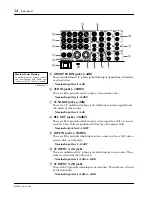
1
ON
L — ST 1 — R
∞
40
30
25
20
15
10
5
0
5
10
∞
40
30
25
20
15
10
5
0
5
10
REC OUT
0
10
TAPE IN
0
10
LEVEL
0
10
PHONES
0
10
TB
ST
AUX 1–4
GRP 1–4
TALKBACK IN
POWER
PHANTOM
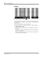
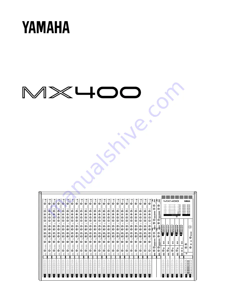
PEAK
+6
+4
+2
0
–2
–4
–7
–10
–15
–20
PEAK
+6
+4
+2
0
–2
–4
–7
–10
–15
–20
PEAK
+6
+4
+2
0
–2
–4
–7
–10
–15
–20
GROUP 1
∞
40
30
15
10
5
0
5
10
20
ON
AFL
PEAK
0
–20
AUX SEND 1
∞
40
30
25
20
15
10
5
0
5
10
PAN
L
R
ON
AFL
TO ST
GROUP 2
∞
40
30
25
20
15
10
5
0
5
10
PAN
L
R
ON
AFL
TO ST
∞
40
30
15
10
5
0
5
10
20
ON
AFL
PEAK
0
–20
AUX SEND 2
GROUP 3
∞
40
30
25
20
15
10
5
0
5
10
PAN
L
R
ON
AFL
TO ST
∞
40
30
15
10
5
0
5
10
20
ON
AFL
PEAK
0
–20
AUX SEND 3
GROUP 4
L
R
∞
40
30
25
20
15
10
5
0
5
10
PAN
ON
AFL
TO ST
∞
40
30
15
10
5
0
5
10
20
ON
AFL
PEAK
0
–20
AUX SEND 4
ST2/MONITOR
∞
40
30
25
20
15
10
5
0
5
10
PFL
ON
L+R
2TR IN
MONI
ST2
∞
40
30
15
10
5
0
5
10
20
ON
AFL
PEAK
0
–20
AUX SEND 5


