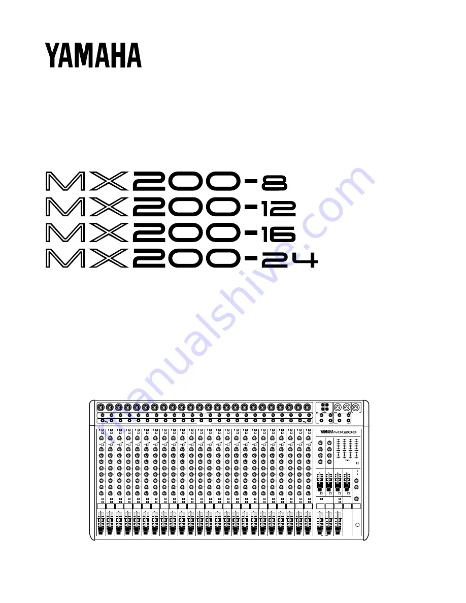
background image

MIXING CONSOLE
TABLE DE MIXAGE
MISCHPULTE
CONSOLA DE MEZCLA

Operation Manual
Manuel d’instructions
Bedienungsanleitung
Manual de Operación

B

A

20dB

PEAK

–16

–60

GAIN

80

–15

+15

HIGH

–15

+15

MID

–15

+15

LOW

0

10

AUX 1

0

10

AUX 2

0

10

AUX 3

0

10

AUX 4

L

R

PAN

PFL

P
O
S
T

P
R
E

10

5

0

5

10

15

20

30

40
00

1

2

3

4

5

6

7

8

–10dB

R

R

L

L

1R

1L/MONO

2R

2L/MONO

3

1

4

2

L

R

+4B

–10dB

TAPE IN

REC OUT

STEREO OUT +4dB

AUX 4dB

AUX SEND +4dB

MONO OUT

0

10

PHONES

–15

+15

HIGH

–15

+15

LOW

0

10

AUX 1

0

10

LEVEL

0

10

REC OUT

0

10

TAPE IN

AUX RETURN 1 AUX RETURN 2

L           ST         R

PHONES

MONO

ON

AFL

AFL

AFL

AFL

AFL

AUX SEND 4

AUX SEND 3

AUX SEND 2

AUX SEND 1

METER SELECT

L       ST      R
1     AUX      2

MONO        PFL/AFL

3      AUX      4

+6

+4

+2

0

–2

–4

–7

–10

–15

–20

–00

+6

+4

+2

0

–2

–4

–7

–10

–15

–20

–00

–15

+15

HIGH

–15

+15

LOW

0

10

AUX 1

0

10

LEVEL

10

5

0

5

10
15
20

30

00

10

5

0

5

10
15
20

30

00

10

5

0

5

10
15
20

30

00

10

5

0

5

10
15
20

30

00

10

5

0

5

10

15

20

30

40
00

10

5

0

5

10

15

20

30

40
00

10

5

0

5

10

15

20

30

40
00

10

5

0

5

10

15

20

30

40
00

B

A

20dB

PEAK

–16

–60

GAIN

80

–15

+15

HIGH

–15

+15

MID

–15

+15

LOW

0

10

AUX 1

0

10

AUX 2

0

10

AUX 3

0

10

AUX 4

L

R

PAN

PFL

P
O
S
T

P
R
E

10

5

0

5

10

15

20

30

40
00

B

A

20dB

PEAK

–16

–60

GAIN

80

–15

+15

HIGH

–15

+15

MID

–15

+15

LOW

0

10

AUX 1

0

10

AUX 2

0

10

AUX 3

0

10

AUX 4

L

R

PAN

PFL

P
O
S
T

P
R
E

10

5

0

5

10

15

20

30

40
00

B

A

20dB

PEAK

–16

–60

GAIN

80

–15

+15

HIGH

–15

+15

MID

–15

+15

LOW

0

10

AUX 1

0

10

AUX 2

0

10

AUX 3

0

10

AUX 4

L

R

PAN

PFL

P
O
S
T

P
R
E

10

5

0

5

10

15

20

30

40
00

B

A

20dB

PEAK

–16

–60

GAIN

80

–15

+15

HIGH

–15

+15

MID

–15

+15

LOW

0

10

AUX 1

0

10

AUX 2

0

10

AUX 3

0

10

AUX 4

L

R

PAN

PFL

P
O
S
T

P
R
E

10

5

0

5

10

15

20

30

40
00

B

A

20dB

PEAK

–16

–60

GAIN

80

–15

+15

HIGH

–15

+15

MID

–15

+15

LOW

0

10

AUX 1

0

10

AUX 2

0

10

AUX 3

0

10

AUX 4

L

R

PAN

PFL

P
O
S
T

P
R
E

10

5

0

5

10

15

20

30

40
00

B

A

20dB

PEAK

–16

–60

GAIN

80

–15

+15

HIGH

–15

+15

MID

–15

+15

LOW

0

10

AUX 1

0

10

AUX 2

0

10

AUX 3

0

10

AUX 4

L

R

PAN

PFL

P
O
S
T

P
R
E

ON

10

5

0

5

10

15

20

30

40
00

B

A

20dB

PEAK

–16

–60

GAIN

80

–15

+15

HIGH

–15

+15

MID

–15

+15

LOW

0

10

AUX 1

0

10

AUX 2

0

10

AUX 3

0

10

AUX 4

L

R

PAN

PFL

P
O
S
T

P
R
E

ON

ON

ON

ON

ON

ON

ON

ON

MIXING CONSOLE

PHANTOM

PFL

INPUT A

INPUT B

OUT IN

INPUT CH INSERT I/O 0dB

OUT IN

1

2

3

4

5

6

7

8

9

1

2

3

4

5

6

7

8

9

1

2

3

4

5

6

7

8

9

10

11

12

13

14

15

16

17

18

19

20

21

22

23

24

10

11

12

13

14

15

16

17

18

19

20

21

22

23

24

10

11

12

13

14

15

16

17

18

19

20

21

22

23

24

B

A

20dB

PEAK

–16

–60

GAIN

80

–15

+15

HIGH

–15

+15

MID

–15

+15

LOW

0

10

AUX 1

0

10

AUX 2

0

10

AUX 3

0

10

AUX 4

L

R

PAN

PFL

P
O
S
T

P
R
E

10

5

0

5

10

15

20

30

40
00

10

5

0

5

10

15

20

30

40
00

B

A

20dB

PEAK

–16

–60

GAIN

80

–15

+15

HIGH

–15

+15

MID

–15

+15

LOW

0

10

AUX 1

0

10

AUX 2

0

10

AUX 3

0

10

AUX 4

L

R

PAN

PFL

P
O
S
T

P
R
E

10

5

0

5

10

15

20

30

40
00

B

A

20dB

PEAK

–16

–60

GAIN

80

–15

+15

HIGH

–15

+15

MID

–15

+15

LOW

0

10

AUX 1

0

10

AUX 2

0

10

AUX 3

0

10

AUX 4

L

R

PAN

PFL

P
O
S
T

P
R
E

10

5

0

5

10

15

20

30

40
00

B

A

20dB

PEAK

–16

–60

GAIN

80

–15

+15

HIGH

–15

+15

MID

–15

+15

LOW

0

10

AUX 1

0

10

AUX 2

0

10

AUX 3

0

10

AUX 4

L

R

PAN

PFL

P
O
S
T

P
R
E

10

5

0

5

10

15

20

30

40
00

B

A

20dB

PEAK

–16

–60

GAIN

80

–15

+15

HIGH

–15

+15

MID

–15

+15

LOW

0

10

AUX 1

0

10

AUX 2

0

10

AUX 3

0

10

AUX 4

L

R

PAN

PFL

P
O
S
T

P
R
E

10

5

0

5

10

15

20

30

40
00

B

A

20dB

PEAK

–16

–60

GAIN

80

–15

+15

HIGH

–15

+15

MID

–15

+15

LOW

0

10

AUX 1

0

10

AUX 2

0

10

AUX 3

0

10

AUX 4

L

R

PAN

PFL

P
O
S
T

P
R
E

10

5

0

5

10

15

20

30

40
00

B

A

20dB

PEAK

–16

–60

GAIN

80

–15

+15

HIGH

–15

+15

MID

–15

+15

LOW

0

10

AUX 1

0

10

AUX 2

0

10

AUX 3

0

10

AUX 4

L

R

PAN

PFL

P
O
S
T

P
R
E

10

5

0

5

10

15

20

30

40
00

B

A

20dB

PEAK

–16

–60

GAIN

80

–15

+15

HIGH

–15

+15

MID

–15

+15

LOW

0

10

AUX 1

0

10

AUX 2

0

10

AUX 3

0

10

AUX 4

L

R

PAN

PFL

P
O
S
T

P
R
E

B

A

20dB

PEAK

–16

–60

GAIN

80

–15

+15

HIGH

–15

+15

MID

–15

+15

LOW

0

10

AUX 1

0

10

AUX 2

0

10

AUX 3

0

10

AUX 4

L

R

PAN

PFL

P
O
S
T

P
R
E

10

5

0

5

10

15

20

30

40
00

10

5

0

5

10

15

20

30

40
00

B

A

20dB

PEAK

–16

–60

GAIN

80

–15

+15

HIGH

–15

+15

MID

–15

+15

LOW

0

10

AUX 1

0

10

AUX 2

0

10

AUX 3

0

10

AUX 4

L

R

PAN

PFL

P
O
S
T

P
R
E

10

5

0

5

10

15

20

30

40
00

B

A

20dB

PEAK

–16

–60

GAIN

80

–15

+15

HIGH

–15

+15

MID

–15

+15

LOW

0

10

AUX 1

0

10

AUX 2

0

10

AUX 3

0

10

AUX 4

L

R

PAN

PFL

P
O
S
T

P
R
E

10

5

0

5

10

15

20

30

40
00

B

A

20dB

PEAK

–16

–60

GAIN

80

–15

+15

HIGH

–15

+15

MID

–15

+15

LOW

0

10

AUX 1

0

10

AUX 2

0

10

AUX 3

0

10

AUX 4

L

R

PAN

PFL

P
O
S
T

P
R
E

10

5

0

5

10

15

20

30

40
00

B

A

20dB

PEAK

–16

–60

GAIN

80

–15

+15

HIGH

–15

+15

MID

–15

+15

LOW

0

10

AUX 1

0

10

AUX 2

0

10

AUX 3

0

10

AUX 4

L

R

PAN

PFL

P
O
S
T

P
R
E

10

5

0

5

10

15

20

30

40
00

B

A

20dB

PEAK

–16

–60

GAIN

80

–15

+15

HIGH

–15

+15

MID

–15

+15

LOW

0

10

AUX 1

0

10

AUX 2

0

10

AUX 3

0

10

AUX 4

L

R

PAN

PFL

P
O
S
T

P
R
E

10

5

0

5

10

15

20

30

40
00

B

A

20dB

PEAK

–16

–60

GAIN

80

–15

+15

HIGH

–15

+15

MID

–15

+15

LOW

0

10

AUX 1

0

10

AUX 2

0

10

AUX 3

0

10

AUX 4

L

R

PAN

PFL

P
O
S
T

P
R
E

10

5

0

5

10

15

20

30

40
00

B

A

20dB

PEAK

–16

–60

GAIN

80

–15

+15

HIGH

–15

+15

MID

–15

+15

LOW

0

10

AUX 1

0

10

AUX 2

0

10

AUX 3

0

10

AUX 4

L

R

PAN

PFL

P
O
S
T

P
R
E

Summary of Contents for MCX-P200

Page 1: ... 18 19 20 21 22 23 24 B A 20dB PEAK 16 60 GAIN 80 15 15 HIGH 15 15 MID 15 15 LOW 0 10 AUX 1 0 10 AUX 2 0 10 AUX 3 0 10 AUX 4 L R PAN PFL P O S T P R E 10 5 0 5 10 15 20 30 40 00 10 5 0 5 10 15 20 30 40 00 B A 20dB PEAK 16 60 GAIN 80 15 15 HIGH 15 15 MID 15 15 LOW 0 10 AUX 1 0 10 AUX 2 0 10 AUX 3 0 10 AUX 4 L R PAN PFL P O S T P R E 10 5 0 5 10 15 20 30 40 00 B A 20dB PEAK 16 60 GAIN 80 15 15 HIGH ...

Page 2: ...ny time XLR type connectors are provided for the INPUT A jacks and phone connectors are provided for the INPUT B jacks allowing easy connections with a variety of input sources The inputs can accept levels ranging from microphones to line level devices Phantom power is provided for easy connection of con denser microphones requiring an external power supply Each input channel has an INPUT CH INSER...

Page 3: ...rear panel matches your local AC mains supply Also make sure that the AC mains supply can deliver more than enough current to handle all equipment used in your system IMPORTANT NOTICE FOR THE UNITED KINGDOM Connecting the Plug and Cord IMPORTANT The wires in this mains lead are coloured in accordance with the following code BLUE NEUTRAL BROWN LIVE As the colours of the wires in the mains lead of t...

Page 4: ...the GAIN control so that the 4 peak indicator lights occasionally If you wish to further reduce the input level use the 2 PAD switch 4 PEAK indicator This indicator detects peak levels after the EQ It will light red at 3dB before clipping to warn that clipping level has nearly been reached 5 80Hz high pass filter switch This switch turns on off a high pass filter that cuts the signal below 80Hz at...

Page 5: ... bus and the AUX1 4 buses When this switch is off the output signal to each bus will be muted completely This switch should be turned off for unused channels 0 Channel PFL switch This switch allows you to monitor the pre fader channel input signal through headphones It is convenient to use PFL when you wish to check the sound of the input signal or when troubleshooting a specific channel A Channel...

Page 6: ...ored in the level meters 8 AUX RETURN 1 2 controls LEVEL The LEVEL knobs control the level at which signals from effect units etc connected to the L MONO R jacks of AUX RETURN 1 2 are sent to the L R bus If a plug is inserted into only the L MONO jack the same signal will be sent to both L and R buses AUX1 AUX2 The AUX1 knobs control the level at which signals from effect units etc connected to th...

Page 7: ...n on an AUX SEND 1 4 AFL switch C METER SELECT switch and meter section The meters are dual function LED meters that indicate signal levels as selected by the METER SELECT switch When METER SELECT is OFF STEREO L R displays the output levels of the STEREO OUT jacks MONO OUT level displays the output level of the MONO OUT jack PFL AFL level displays the input level of the channel whose PFL switch i...

Page 8: ...an be changed to move the MONO OUT signal so that it is taken after the ST fader If you would like this change to be made consult with your dealer ON ON R L STEREO OUT MONO OUT INV INV SUM SUM SUM INV INV ON ON R L STEREO OUT MONO OUT INV INV SUM SUM SUM 1 INPUT A These are XLR type connectors 1 sleeve 2 hot 3 cold Microphones of 50 600Ω or 600Ω line level devices can be connected here When the PH...

Page 9: ...ANTOM OFF ON 1 POWER switch This switch turns on the power of the mixer When turning off the power of audio equipment it is im portant to start with the device closest to the speakers Normally this will be the power amp 2 PHANTOM switch This switch turns on off the phantom power supply for all channels Use this switch when you are using condenser microphones When this switch is turned on DC 48V wi...

Page 10: ...ND1 88 Mic and line input 88 AUX RTN2 AUX RTN1 AUX SEND4 AUX SEND3 AUX SEND2 Cassette Deck or DAT TAPE IN REC OUT Stage monitors Front of house main speakers Power amp Power amp Graphic EQ Headphone Effects processor Application Example ...

Page 11: ...SEND 3 4 16dB AUX RETURN 1 2 to STEREO OUT 16dB AUX RETURN 1 2 to AUX SEND 1 2 28dB TAPE In 1 2 to STEREO OUT Crosstalk at 1kHz 70dB between input channels 70dB between output channels Gain control input channel 44dB variable 60 16dB Pad switch input channel 0 20dB Input channel equalization 15dB maximum boost or cut HIGH 12kHz shelving MID 2 5kHz peaking LOW 80Hz shelving Turnover rolloff frequen...

Page 12: ...kΩ 12dB 4dB 20dB Unbalanced 1 2 195mV 1 23V 7 75V phone jack INSERT IN 5kΩ 600Ω line 20dB 0dB 20dB Phone jack TRS 77 5mV 775mV 7 75V T OUT R IN S GND TAPE IN 10kΩ 26dBV 10dBV RCA pin jack 50 1mV 316mV 0dB 0 775 Vrms 0dBV 1 Vrms Output specifications Output connector Output impedance Nominal impedance Output level Connector type Nominal Max before clipping STEREO OUT L R 150Ω 600Ω Lines 4dB 1 23V 2...

Page 13: ...HA PAD 20dB 8 12 16 24 1 INPUT B 1 INPUT A PHANTOM PHANTOM INPUT A PEAK 0dB 1 INSERT I O INPUT CH 48V ON OFF PHANTOM EQ 3BAND A B 80 PFL PHONES METER METER PHONES METER AUX 2 TAPE IN INV INV EQ 2BAND EQ 2BAND SUM AUX 1 PFL LEVEL INV INV AUX 4 AUX 3 AUX 2 AUX 1 PAN CTRL PFL AFL PFL AFL AUX STEREO INV SUM ST OUT METER AFL INV SUM AFL SUM REC OUT SUM SUM INV INV ON Same as AUX RETURN 1 SUM AUX RETURN...

Page 14: ...12 W 897 657 537 417 929 689 569 449 Wi MX200 12 MX200 24 MX200 16 MX200 8 MODEL D 461 7 W Wi 54 5 54 5 H 124 6 57 3 295 54 5 8 101 2 80 6 Dimensions Units mm ...

Page 15: ...Français TABLE DE MIXAGE Manuel d instructions ...

Page 16: ...ur les prises d entrée B INPUT B permettant des connexions faciles avec diverses sources d entrée Les entrées acceptent des niveaux allant des microphones aux appareils de niveau de ligne L alimentation fantôme est fournie pour une connexion fa cile des microphones à condensateur nécessitant une ali mentation externe Chaque canal d entrée possède une prise E S d insertion de canal INPUT CH INSERT ...

Page 17: ...technicien Yamaha qualifié Toute tentative d ouver ture du boîtier et de manipulation des circuits internes se soldera par la perte du bénéfice de la garantie 5 Coupez toujours l alimentation avant de procéder à des branchements N oubliez jamais de mettre les appareils hors tension avant de brancher ou de débrancher des câbles afin de ne pas en dommager l appareil lui même ainsi que le matériel qu...

Page 18: ... commande de GAIN est ajusté de façon à ce que l indicateur de crête 4s allume occasionnellement Si on veut réduire d avantage le ni veau d entrée utiliser le commutateur PAD 2 4 Indicateur de crête PEAK Cet indicateur détecte les niveaux de crête après l égaliseur Il s allume en rouge à 3dB avant l écrêtage pour avertir que le niveau d écrêtage est presque atteint 5 Commutateur de filtre passe ha...

Page 19: ...D et aux bus AUX1 4 Lorsque ce commutateur est désactivé le signal de sortie à chaque bus est rendu complètement silencieux Ce com mutateur doit être désactivé pour les canaux inutilisés 0 Commutateur de canal PFL Ce commutateur permet de contrôler le signal d entrée de canal du pré fader avec le casque Il est commode d utiliser le commutateur PFL lorsqu on veut vérifier le son du signal d entrée ...

Page 20: ... SEND 1 4 AFL Lorsqu on veut contrôler les signaux de sortie envoyés aux sorties auxiliaires 1 4 AUX SEND 1 4 appuyer sur le commutateur approprié Le niveau de la sortie auxiliaire AUX SEND dont le com mutateur est activé est indiqué par le vu mètre PFL AFL 7 Faders de sortie auxiliaire AUX SEND Ces faders ajustent le niveau des signaux de sortie envoyés des sorties auxiliaires AUX SEND 1 4 Le com...

Page 21: ...à DEL à double fonction qui indiquent les niveaux des signaux sélectionnés à l aide du commutateur de sélection de vu mètre METER SELECT Lorsque le commutateur de sélection de vu mètre METER SELECT est désactivé OFF STEREO G D affiche les niveaux de sortie des pri ses de sortie stéréo STEREO OUT Niveau MONO OUT sortie mono affiche le niveau de sortie de la prise de sortie mono MONO OUT Niveau PFL ...

Page 22: ...e sortie nominal et l impédance est de 0dB 10Ω Ces prises permettent d insérer vos propres égaliseurs graphi ques compresseurs filtres anti parasites ou autres éléments INSERT OUT sortie d insertion INSERT IN entrée d insertion 4 Entrée cassette TAPE IN Votre platine DAT ou platine cassette peut être connectée directement à cette borne pour un contrôle pratique Utili ser la commande d entrée casse...

Page 23: ...che est insérée seulement dans G MONO le même signal est envoyé aux deux bus G et D Panneau arrière 1 Interrupteur d alimentation POWER Cet interrupteur allume la console de mixage Pour éteindre un équipement audio il est important de commencer par l appareil situé le plus près des enceintes Normalement il s agit de l amplificateur de puissance 2 Commutateur fantôme PHANTOM Ce commutateur active d...

Page 24: ...urs de salle Amplificateur Amplificateur Casque STEREO OUT 88 88 AUX RTN2 AUX RTN1 AUX SEND4 AUX SEND3 Platine à bobines DAT TAPE IN REC OUT Equaliseur graphique Entrées ligne et micro Processeur d effets AUX SEND1 AUX SEND2 Exemple d application ...

Page 25: ...MONO OUT 80dB entrée de canal CH IN à la sortie auxiliaire AUX SEND 1 2 90dB entrée de canal CH IN à la sortie auxiliaire AUX SEND 3 4 16dB retour auxiliaire AUX RETURN 1 2 à la sortie stéréo STEREO OUT 16dB retour auxiliaire AUX RETURN 1 2 à la sortie auxiliaire AUX SEND 1 2 28dB entrée cassette TAPE IN 1 2 à la sortie stéréo STEREO OUT Diaphonie à 1kHz 70dB entre canaux d entrée 70dB entre canau...

Page 26: ...ON 16 16dB 4dB 24dB Prise casque TRS 20dB Ligne de 600Ω 123mV 1 23V 12 3V T point chaud R froid S GND terre AUX RETURN 10kΩ 12dB 4dB 20dB Prise casque 1 2 195mV 1 23V 7 75V asymétrique INSERT IN 5kΩ Ligne de 600Ω 20dB 0dB 20dB Prise casque TRS 77 5mV 775mV 7 75V T OUT sortie R IN entrée S GND terre TAPE IN 10kΩ 26dBV 10dBV 50 1mV 316mV Prise à broche RCA 0dB 0 775Vrms 0dBV 1Vrms Caractéristiques d...

Page 27: ...GAIN HA PAD 20dB 8 12 16 24 1 INPUT B 1 INPUT A PHANTOM PHANTOM INPUT A PEAK 0dB 1 INSERT I O INPUT CH 48V ON OFF PHANTOM EQ 3BAND A B 80 PFL PHONES METER METER PHONES METER AUX 2 TAPE IN INV INV EQ 2BAND EQ 2BAND SUM AUX 1 PFL LEVEL INV INV AUX 4 AUX 3 AUX 2 AUX 1 PAN CTRL PFL AFL PFL AFL AUX STEREO INV SUM ST OUT METER AFL INV SUM AFL SUM REC OUT SUM SUM INV INV ON Same as AUX RETURN 1 SUM AUX R...

Page 28: ...12 W 897 657 537 417 929 689 569 449 Wi MX200 12 MX200 24 MX200 16 MX200 8 MODEL D 461 7 W Wi 54 5 54 5 H 124 6 57 3 295 54 5 8 101 2 80 6 Dimensions Unité mm ...

Page 29: ...X200 12 MX200 16 MX200 24 Gerät Typ Bezeichnung in Übereinstimmung mit den Bestimmungen der 82 499 EWG EG Richtlinie funkentstört ist Der Deutschen Bundespost wurde das Inverkehrbringen dieses Gerätes angezeigt und die Berechtigung zur Überprüfung der Serie auf Einhaltung der Bestimmungen eingeräumt YAMAHA Europa GmbH Name des Importeurs ...

Page 30: ...und R MONO OUT bzw sowie AUX SEND anliegen mit einem Kopfhörer überwachen Bei den Eingängen INPUT A handelt es sich um symmetri sche XLR Buchsen während der Eingangsbuchsensatz INPUT B für symmetrische Klinkenstecker vorgesehen ist Die Eingänge können einen Pegelbereich zwischen Mi krofon und Line Pegeln verarbeiten Dank einer Phantomstromversorgung können auch Kondensatormikrofone problemlos ange...

Page 31: ...Sie daß beim Öffnen des Gehäuses automatisch der Garantieanspruch erlischt 5 Schalten Sie das Pult aus bevor Sie die Anschlüsse vor nehmen oder ändern Schalten Sie das MX200 immer AUS bevor Sie Kabel an schließen oder abtrennen Das ist sehr wichtig damit we der das Pult noch die daran angeschlossenen Geräte be schädigt werden 6 Behandeln Sie die Kabel mit der gebotenen Umsicht Daß man Kabelanschlü...

Page 32: ...IN Regler so einstellen daß die Spitzenwertanzeige 4 nur gelegentlich aufblinkt Falls der Eingangspegel weiter reduziert werden muß den Dämpfungsschalter 2 verwenden 4 Spitzenwertanzeige PEAK Diese Anzeige erfaßt den Signalpegel hinter dem Equalizer Sie leuchtet 3dB unter dem Abkappegel rot auf um zu warnen daß das Signal nahezu den Begrenzungspegel erreicht 5 80Hz Hochpaßfilterschalter Dient zum ...

Page 33: ...nalwege vom Ein gangskanal zu den Sammelschienen STEREO L R und AUX1 4 geöffnet Durch Ausrasten des Schalters werden die Ausgänge zu den Sammelschienen stummgeschaltet Daher sollte der Schalter bei unbeschalteten Kanälen auf AUS gestellt wer den 0 Eingangssignal Abhörschalter PFL Durch diesen Schalter können Sie das Eingangssignal ab hören bevor es den Kanalfader durchläuft Daher bietet sich diese...

Page 34: ...gangspegel an der MONO OUT Buchse 6 AUX Sendesignal Abhörschalter AUX SEND 1 4 AFL Um Signale abzuhören die über eine der vier AUX SEND Sammelschienen ausgegeben werden den entsprechenden AFL Schalter drücken Der Pegel des abgehörten AUX Sendesignals wird durch die PFL AFL Pegelmesser rechts angezeigt 7 AUX Sendefader AUX SEND Diese Fader steuern den Ausgangspegel der entsprechen den AUX SEND Samm...

Page 35: ... den AUX SEND Bedienfeldern 1 4 drük ken C Pegelanzeige Wahlschalter METER SELECT und Pegelanzeigen Die LED Pegelanzeigen haben zwei Anzeigefunktionen zwischen denen mit METER SELECT umgeschaltet wird METER SELECT ausgerastet STEREO L R gibt den Ausgangspegel an den STEREO OUT Buchsen an MONO zeigt den Ausgangspegel an der MONO OUT Buchse PFL AFL zeigt den Eingangspegel eines Kanals dessen PFL Sch...

Page 36: ...inalausgangspegel und die Ausgangsimpedanz betragen 0dB bzw 10kΩ Diese Buchsen erlauben das Zwischenschalten von eige nen graphischen Equalizern Kompressoren Rauschfiltern usw in die Eingangskanäle Schleifenausgang INSERT OUT Schleifeneingang INSERT IN 4 Band Eingangsbuchse TAPE IN Zur Materialüberprüfung usw kann hier ein DAT oder Cassettendeck angeschlossen werden Der Eingangspegel wird mit dem ...

Page 37: ...et werden Wird nur die Buchse L MONO beschaltet wird das glei che Signal auf die linke und rechte Stereo Sammelschiene gelegt Geräterückseite 1 Netzschalter POWER Dient zum Ein und Ausschalten des Mischpults Das Ausschalten von Audio Anlagen sollte mit den Gerä ten begonnen werden die direkt vor den Lautsprechern an geordnet sind Normalerweise ist das die Endstufe 2 Phantom Stromversorgungsschalte...

Page 38: ...ine Eingänge MIXING CONSOLE STEREO OUT 88 88 AUX RTN2 AUX RTN1 AUX SEND4 AUX SEND3 Tonbandgerät DAT TAPE IN REC OUT Bühnenmonitore Saalbeschallung Endstufe Endstufe Graphischer Equalizer Kopfhörer Außenbordeffektgerät AUX SEND1 AUX SEND2 ...

Page 39: ...dB TAPE IN 1 2 zu STEREO OUT Übersprechdämpfung bei 1kHz 70dB zwischen Eingangskanälen 70dB zwischen Ausgangskanälen Verstärkungsfaktorregler Eingangskanal 44dB 60 16dB Dämpfungsschalter Eingangskanal 0 20dB Eingangskanal Equalizer 15dB maximale Pegelanhebung absenkung HIGH Scheitelfrequenz 12kHz MID Mittenfrequenz 2 5kHz LOW Scheitelfrequenz 80Hz Übergangs Abfallfrequenzen 3dB unter maximaler Peg...

Page 40: ... 2 195mV 1 23V 7 75V Klinkensteckerbuchse INSERT IN 5kΩ 600Ω line 20dB 0dB 20dB Klinkensteckerbuchse TRS 77 5mV 775mV 7 75V T Spitze Ausgang R Ring Eingang S Hülse Masse TAPE IN 10kΩ 26dBV 10dBV Cinchbuchsen 50 1mV 316mV 0dB 0 775 Vrms 0dBV 1 Vrms Ausgangsdaten Ausgangsbuchse Ausgangsim Nennimpedanz Ausgangspegel Anschlußtyp pedanz Nominalpegel Maximum bis Abkappegel STEREO OUT L R 150Ω 600Ω Hochp...

Page 41: ...AIN HA PAD 20dB 8 12 16 24 1 INPUT B 1 INPUT A PHANTOM PHANTOM INPUT A PEAK 0dB 1 INSERT I O INPUT CH 48V ON OFF PHANTOM EQ 3BAND A B 80 PFL PHONES METER METER PHONES METER AUX 2 TAPE IN INV INV EQ 2BAND EQ 2BAND SUM AUX 1 PFL LEVEL INV INV AUX 4 AUX 3 AUX 2 AUX 1 PAN CTRL PFL AFL PFL AFL AUX STEREO INV SUM ST OUT METER AFL INV SUM AFL SUM REC OUT SUM SUM INV INV ON Same as AUX RETURN 1 SUM AUX RE...

Page 42: ...12 W 897 657 537 417 929 689 569 449 Wi MX200 12 MX200 24 MX200 16 MX200 8 MODEL D 461 7 W Wi 54 5 54 5 H 124 6 57 3 295 54 5 8 101 2 80 6 Abmessungen Einheit mm ...

Page 43: ...Español CONSOLA DE MEZCLA Manual de Operación ...

Page 44: ...es de auriculares para las tomas de entrada B INPUT B permitiendo realizar fáciles conexiones con una serie de diferentes fuentes de entrada Las entradas pueden aceptar niveles que abarcan desde micrófonos hasta dispositivos de nivel de línea La alimentación Phantom se facilita para conseguir una conexión sencilla de los micrófonos de condensador que necesitan una fuente de alimentación externa Ca...

Page 45: ...ento avise a personal cualificado de Yamaha Si abre la cubierta y o intenta forzar los circuitos internos la garantía quedará anulada 5 Apague siempre el aparato antes de hacer las conexiones Apague siempre el aparato OFF antes de ponerse a conectar o desconectar los cables Acuérdese siempre de hacerlo para evitar dañar el aparato u otros equipos que puedan estar conectados a él 6 Maneje los cable...

Page 46: ...ntrol de Ganancia para que el indicador de máximo 4 se ilumine de vez en cuando Si usted desea reducir aún más el nivel de entrada utilice el interruptor atenuador 2 4 Indicador de máximo PEAK Este indicador detecta los niveles de máximo después de que la señal atraviese el equalizador Se iluminará en color rojo a 3dB antes del corte para avisar que ya casi se ha alcanzado el nivel de corte 5 Inte...

Page 47: ...o STEREO L R y hacia los buses auxiliares 1 4 AUX 1 4 Cuando este interruptor está apagado la señal de salida hacia cada bus quedará completamente silenciada Este interruptor debería apagarse para aquellos canales que no se estén utilizando 0 Interruptor de escucha pre atenuador PFL de canal Este interruptor le permite controlar la señal de entrada al canal pre atenuador mediante los auriculares E...

Page 48: ...El interruptor del selector de medidor 8 METER SELECT se puede colocar de forma que estas señales de envío auxiliar AUX SEND sean controladas desde los medidores de nivel 8 Controles auxiliares de retorno 1 2 AUX RETURN 1 2 LEVEL Los mandos de nivel LEVEL controlan el nivel al cual las señales provenientes de las unidades de efectos etc conectadas a las tomas monoaurales izquierda derecha L MONO R...

Page 49: ...or METER SELECT y sección del medidor Los medidores son medidores con diodos fotoemisores de doble función que indican los niveles de las señales que son seleccionados por el interruptor Selector de Medidor METER SELECT Cuando está apagado OFF el selector de medidor METER SELECT Estéreo izquierda derecha STEREO L R exhibe en el visualizador los niveles de salida de las tomas de salida estereofónic...

Page 50: ...ación Utilice el control de entrada de cinta TAPE IN para ajustar el nivel sección de control principal 0 5 Salida de grabación REC OUT Usted puede conectar su platina de cinta de audio digital DAT o platina de cassette aquí para grabar señales de audio desde la salida estereofónica STEREO OUT En este caso el nivel de salida final se ajusta mediante el con trol de salida de grabación REC OUT secci...

Page 51: ...nciende la alimentación de la consola de mezclas Cuando se va a apagar la alimentación de un equipo de audio es importante empezar por el dispositivo más cercano a los altavoces Normalmente se tratará del amplificador de potencia 1 Interruptor PHANTOM Este interruptor enciende y apaga el suministro de alimentación Phantom para todos los canales Utilice este interruptor cuando esté utilizando micró...

Page 52: ...UX RTN1 AUX SEND4 AUX SEND3 Platina de cinta o DAT TAPE IN REC OUT Monitores de escenario Altavoces principales frente al edificio Amplificador de potencia Amplificador de potencia Ecualizador gráfico Auriculares Procesador de efectos AUX SEND1 AUX SEND2 Ejemplo aplicable ...

Page 53: ...80dB CH IN a AUX SEND 1 2 90dB CH IN a AUX SEND 3 4 16dB AUX RETURN 1 2 a STEREO OUT 16dB AUX RETURN 1 2 a AUX SEND 1 2 28dB TAPE IN 1 2 a STEREO OUT Interferencia entre canales a 1kHz 70dB entre canales de entrada 70dB entre canales de salida Control de ganancia 44dB variable 60 16dB canales de entrada Interruptor atenuador 0 20dB canales de entrada Equalización de canal de entrada 15dB máxima in...

Page 54: ...es TRS 20dB Línea 600Ω 123mV 1 23V 12 3V T Caliente R Frío S Tierra AUX RETURN 10kΩ 12dB 4dB 20dB Toma de auriculares 1 2 195mV 1 23V 7 75V no simétrica INSERT IN 5kΩ Línea 600Ω 20dB 0dB 20dB Toma de auriculares TRS 77 5mV 775mV 7 75V T Salida R Entrada S Tierra TAPE IN 10kΩ 26dBV 10dBV Toma de pin RCA 50 1mV 316mV 0dB 0 775 Vrms 0dBV 1 Vrms Especificaciones de salida Conector de salida Impedancia...

Page 55: ...IN HA PAD 20dB 8 12 16 24 1 INPUT B 1 INPUT A PHANTOM PHANTOM INPUT A PEAK 0dB 1 INSERT I O INPUT CH 48V ON OFF PHANTOM EQ 3BAND A B 80 PFL PHONES METER METER PHONES METER AUX 2 TAPE IN INV INV EQ 2BAND EQ 2BAND SUM AUX 1 PFL LEVEL INV INV AUX 4 AUX 3 AUX 2 AUX 1 PAN CTRL PFL AFL PFL AFL AUX STEREO INV SUM ST OUT METER AFL INV SUM AFL SUM REC OUT SUM SUM INV INV ON Same as AUX RETURN 1 SUM AUX RET...

Page 56: ...12 W 897 657 537 417 929 689 569 449 Wi MX200 12 MX200 24 MX200 16 MX200 8 MODEL D 461 7 W Wi 54 5 54 5 H 124 6 57 3 295 54 5 8 101 2 80 6 Dimensions Unidades mm ...

Page 57: ...YAMAHA CORPORATION R0 1 IP Printed in Korea P O Box 1 Hamamatsu Japan ...

Reviews: