Yamaha K-200, Service Manual
The Yamaha K-200 Service Manual is a comprehensive guide that provides detailed instructions for operating and maintaining your Yamaha K-200 device. This manual is available for free download at manualshive.com, ensuring you have all the necessary information to optimize your experience with this exceptional product.
Share
Download


Reviews:
No comments
Related manuals for K-200

130
Brand: Tascam Pages: 2

700
Brand: Nakamichi Pages: 16
CR-2
Brand: Nakamichi Pages: 36
CR-2
Brand: Nakamichi Pages: 9
322
Brand: Tascam Pages: 5
6155
Brand: NAD Pages: 3
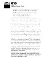
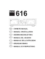
616
Brand: NAD Pages: 2
616
Brand: NAD Pages: 58

RQ-SW88V
Brand: Panasonic Pages: 2

RQ-CR18V
Brand: Panasonic Pages: 4

RQ-2102 - Cassette Recorder
Brand: Panasonic Pages: 7

RQ-SX47
Brand: Panasonic Pages: 4

RQ-SX53
Brand: Panasonic Pages: 3

RQ-SX47
Brand: Panasonic Pages: 2

RQ-CR15V
Brand: Panasonic Pages: 3

RQ-SX43
Brand: Panasonic Pages: 3

RQ-SX76
Brand: Panasonic Pages: 4

RQE20V - PERSONAL STEREO-LOW
Brand: Panasonic Pages: 10


