YAMAHA ELECTRONICS CORPORATION, USA
6660 ORANGETHORPE AVE., BUENA PARK, CALIF. 90620, U.S.A.
YAMAHA CANADA MUSIC LTD.
135 MILNER AVE., SCARBOROUGH, ONTARIO M1S 3R1, CANADA
YAMAHA ELECTRONIK EUROPA G.m.b.H.
SIEMENSSTR. 22-34, 25462 RELLINGEN BEI HAMBURG, GERMANY
YAMAHA ELECTRONIQUE FRANCE S.A.
RUE AMBROISE CROIZAT BP70 CROISSY-BEAUBOURG 77312 MARNE-LA-VALLEE CEDEX02, FRANCE
YAMAHA ELECTRONICS (UK) LTD.
YAMAHA HOUSE, 200 RICKMANSWORTH ROAD WATFORD, HERTS WD18 7GQ, ENGLAND
YAMAHA SCANDINAVIA A.B.
J A WETTERGRENS GATA 1, BOX 30053, 400 43 VÄSTRA FRÖLUNDA, SWEDEN
YAMAHA MUSIC AUSTRALIA PTY, LTD.
17-33 MARKET ST., SOUTH MELBOURNE, 3205 VIC., AUSTRALIA
© 2006 All rights reserved.
HTR-5940
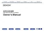
HTR-5940
AV Receiver
OWNER’S MANUAL
U
Printed in Malaysia
WG73630
HTR-5940_U_cv.fm Page 1 Monday, December 12, 2005 7:35 PM
Summary of Contents for HTR-5940
Page 1: ...HTR 5940 HTR 5940 AV Receiver OWNER S MANUAL U ...
Page 126: ...YST SW216 Subwoofer System UB OWNER S MANUAL ...
Page 143: ......
Page 144: ......
Page 146: ...U B YST SW315 YST SW215 Subwoofer System OWNER S MANUAL ...
Page 169: ...Printed in Indonesia WB35910 1 ...