background image

Generator

LIT-19626-01-16

7TA-28199-11

PRINTED ON RECYCLED PAPER

PRINTED IN JAPAN

03

9

08 – 0.5 

×

!

EF1000A

OWNER’S MANUAL

 7TA-9-11 hyoshi  10/24/03 4:14 PM  Page 1

Summary of Contents for EF1000A

Page 1: ...Generator LIT 19626 01 16 7TA 28199 11 EF1000A OWNER S MANUAL ...

Page 2: ......

Page 3: ...se numbers for reference when ordering parts from a Yamaha deal er AE00002 INTRODUCTION Congratulations on your purchase of your new Yamaha This manual will provide you with a good basic understanding of the operation and maintenance of this machine If you have any questions regarding the operation or maintenance of your machine please consult a Yamaha dealer PRI I D NUMBER EF1000A OWNER S MANUAL ...

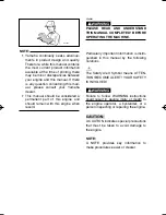
Page 4: ...th this engine when resold AE00032 w PLEASE READ AND UNDERSTAND THIS MANUAL COMPLETELY BEFORE OPERATING THE MACHINE Particularly important information is distin guished in this manual by the following notations The Safety Alert Symbol means ATTEN TION BECOME ALERT YOUR SAFETY IS INVOLVED w Failure to follow WARNING instructions could result in severe injury or death to the engine operator a bystan...

Page 5: ...OTECTOR 9 PRE OPERATION CHECK 10 FUEL 10 ENGINE OIL 11 GROUND Earth 11 OPERATION 12 STARTING THE ENGINE 12 APPLICATION RANGE 13 CONNECTION 14 STOPPING THE ENGINE 15 PERIODIC MAINTENANCE 16 MAINTENANCE CHART 16 SPARK PLUG INSPECTION 18 CARBURETOR ADJUSTMENT 18 ENGINE OIL REPLACEMENT 19 AIR FILTER 20 FUEL COCK 21 FUEL TANK FILTER 21 MUFFLER SPARK ARRESTER 22 TROUBLESHOOTING 23 STORAGE 25 DRAIN THE F...

Page 6: ...aintenance THE CUSTOMER S RESPONSIBILITY under this warranty shall be to 1 Operate and maintain the generator as spec ified in the appropriate Owner s Manual 2 Give notice to an authorized Yamaha con sumer generator dealer of any and all appar ent defects within ten 10 days after discov ery and make the unit available at that time for inspection and repairs at such dealer s place of business WARRA...

Page 7: ...le and upon your request at any later date In addition each Yamaha generator dealer is held responsible for his setup service and warranty repair work Q Is the warranty transferable to second own ers A Yes The remainder of the existing warranty can be transfered upon request The unit has to be inspected and reregis tered by an authorized Yamaha generator dealer for the policy to remain effective C...

Page 8: ...zz J IN TYPE z zz z zz EX z zz z zz zzzz zzzz AT NO LOAD SE SAE 10W 30 EMISSIONS COMPLIANCE PERIOD CATEGORY A EPA WARNING READ THE OWNER S MANUAL AND ALL LABELS BEFORE OPERATING q q AVERTISSEMENT 8 ONLY OPERATE IN WELL VENTILATED AREA EXHAUST GAS CONTAINS POISONOUS CARBON MONOXIDE CHECK FOR SPILLED FUEL OR FUEL LEAKS STOP ENGINE BEFORE REFUELING DO NOT OPERATE NEAR FLAMMABLE MATERIALS ELECTROCUTIO...

Page 9: ...e care not to spill any fuel on the engine or muffler when refuelling 9 If you swallow any fuel inhale fuel vapor or allow any to get in your eye s see your doctor immedi ately If any fuel spills on your skin or clothing immediately wash with soap and water and change your clothes 9 When operating or transporting the machine be sure it is kept upright If it tilts fuel may leak from the carburetor ...

Page 10: ... with a dust cover 741 044 q 9 Be sure the carrying handle is securely installed before picking up the generator 9 Be sure to carry the generator only by its carrying handle s 1 Carrying handle 741 038 AE00083 ELECTRIC SHOCK PREVENTION 9 Never operate the engine in rain or snow 742 002 9 Never touch the machine with wet hands or elec trical shock will occur ...

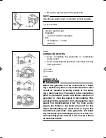
Page 11: ...r can be connected to a build ing s electrical system a licensed electrician must install an isolation transfer switch in the build ing s main fuse box The switch is the connection point for generator power and allows selection of generator or main line power to the building This will prevent the generator from charging the main power line backfeeding when the main power supply has failed or has b...

Page 12: ...total length should not exceed 60 meters for cross section of 1 5 mm square and 100 meters for cross section of 2 5 mm square or more 9 This extension cord should be protected by a tough flexible rubber sheath IEC 245 or the equivalent to withstand mechanical stresses ...

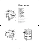
Page 13: ...cap 3 Fuel cock 4 Air filter cover 5 Spark plug 6 Muffler 7 Choke lever 8 AC receptacle 9 Engine switch 0 Ground Earth terminal q Recoil starter w AC protector e Carrying handle r Fuel level gauge t Oil filler cap q w 2 i 0 o 5 1 r e 793 021 u 3 4 t y 793 022 i 2 0 793 023 ...

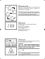
Page 14: ...OTE Press to reset the AC protector AE00112 OIL WARNING SYSTEM When the oil level falls below the lower level the engine stops automatically Unless you refill with oil the engine will not start again NOTE If the engine stalls or does not start check the oil level If the oil is insufficient add oil and restart AE00122 ENGINE SWITCH The engine switch controls the ignition system 1 I 7 ON Ignition ci...

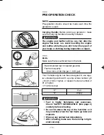
Page 15: ...6 FUEL Make sure there is sufficient fuel in the tank Your Yamaha engine has been designed to use regu lar unleaded gasoline with a pump octane number R M 2 of 86 or higher or research octane number of 91 or higher 1 Fuel level gauge w 9 Fuel is highly flammable and poisonous Check SAFETY INFORMATION See page 4 carefully before refueling 9 Do not fill above the top of the fuel filter or it may ove...

Page 16: ...essary 1 Upper level NOTE Recommended engine oil classification API Service SE or SF cC The generator has been shipped without engine oil Fill with oil or it will not start Recommended oil å YAMALUBE 4 10W 30 or SAE 10W 30 type SE motor oil SAE 30 ç SAE 20 SAE 10W Engine oil quantity 0 43 L 0 38 lmp qt 0 45 US qt AE00241 GROUND Earth Make sure to ground earth the generator Check SAFETY INFORMATION...

Page 17: ...ices 1 Turn the fuel cock lever to the ON position 1 ON 2 Turn the engine switch to the I 7 position 1 I 7 ON 3 Turn the choke lever to the 1 position 1 Choke lever NOTE The choke is not required to start a warm engine Turn the choke lever to the operating position 4 Pull slowly on the recoil starter until it is engaged then pull it briskly 5 After the engine starts warm up the engine until the en...

Page 18: ...ome precision equipment is voltage sensitive and may require a more uniform voltage supply than portable generators provide Examples include some medical equipment personal computers and some inverters that sense peak and RMS voltage values Consult the precision equipment vendor before relying on any portable generator to provide power to such equipment AC Power factor 1 0 8 0 95 0 4 0 75 Efficien...

Page 19: ...ithin generator rated output 9 Be sure the receptacle load current is within receptacle rated current 1 Wind the power lead 2 or 3 turns around handle 2 Start the engine 3 Plug into AC receptacle 761 001 761 054a 763 165 q w 763 005a 4 Press in the AC protector and turn on any electric devices cC Reduce the load to the specified generator rated output if the AC protector turns off If it turns off ...

Page 20: ...763 164d q 705 038 q AE00834 STOPPING THE ENGINE NOTE Turn off any electric devices 1 Disconnect any electric devices 2 Turn the engine switch to the 3 5 position 1 3 5 STOP 3 Turn the fuel cock lever to OFF 1 OFF ...

Page 21: ...and adjust 2 Valve Clearance when engine is 0 cold Check breather hose for cracks or 0 3 Crankcase damage Replace breather system if necessary Check and adjust 0 4 Idle speed engine idle speed Check for leakage Retighten or 0 replace gasket 5 Exhaust System if necessary Check muffler screen and spark arrester Clean 0 replace if necessary Check oil level 0 6 Engine Oil Replace 0 0 Clean 7 Air Filte...

Page 22: ...l Line for crack or da 0 mage Replace if necessary 10 Check choke 0 Choke lever operation 11 Cooling System Check for fan 0 damage 12 Starting System Check recoil 0 starter operation 13 More frequently 0 Decarbonization if necessary Check all fittings 14 Fittings and fasteners 0 Fasteners Correct if necessary No Item Remarks Pre Ope ration check daily Initial Every 1 month or 20 Hr 3 months or 50 ...

Page 23: ...and gap a Gap 3 Install the spark plug Standard electrode color Tan Color Standard Spark Plug BPR6HS NGK Spark Plug Gap 0 6 0 7 mm 0 024 0 028 in Spark Plug Torque 20 N m 2 kgf m 14 lbf ft AE00431 CARBURETOR ADJUSTMENT The carburetor is a vital part of the engine Adjusting should be left to a Yamaha dealer with the profession al knowledge specialized data and equipment to do so properly ...

Page 24: ...er cap 3 Place an oil pan under the engine Drain the oil completely 4 Check the oil filler cap and O ring If damaged replace 1 Oil filler cap 2 O ring 5 Add engine oil to the upper level 1 Upper level NOTE Recommended engine oil classification API Service SE or SF cC Be sure no foreign material enters the crankcase Recommended oil å YAMALUBE 4 10W 30 or SAE 10W 30 type SE motor oil SAE 30 ç SAE 20...

Page 25: ... not wring out the element This could cause it to tear 4 Insert the element into the air filter NOTE Be sure the element sealing surface matches the air filter so there is no air leak cC The engine should never run without the element excessive piston and cylinder wear may result w Never use solvent while smoking or in the vicinity of an open flame Recommended oil Foam air filter oil or SAE 20 mot...

Page 26: ...uel cock cup and gasket 4 Clean the cup with solvent and wipe it off 5 Check the gasket Replace it if damaged 6 Reinstall the gasket and fuel cock cup w Be sure the fuel cock cup is tightened securely AE00471 FUEL TANK FILTER 1 Remove the fuel tank cap and filter 1 Filter 2 Clean the filter with solvent If damaged replace 3 Wipe the filter and insert it w Be sure the tank cap is tightened securely...

Page 27: ...he engine and muffler while they are still hot with any part of your body or clothing during inspection or repair 1 Remove the muffler protector 1 2 Remove the plate 2 711 039 q 3 Tap the muffler lightly then take out the loose car bon deposits from inside the muffler 4 Reinstall by reversing the removal procedure w 711 040 711 041 ...

Page 28: ...ean fuel cock 2 Clogged carburetor Clean carburetor 2 Engine oil system Insufficient 2 Oil level is low Add engine oil 3 Electrical systems 2 Engine switch to ON Poor spark 2 Spark plug dirty with carbon or wet Remove carbon or wipe spark plug dry 2 Faulty ignition system Consult dealer 4 Compression Insufficient 2 Worn out piston and cylinder Consult dealer 2 Loose cylinder head nuts Tighten nuts...

Page 29: ...DS be sure to place the spark plug as far way as possible from the spark plug hole and carburetor area 9 To prevent ELECTRIC SHOCK do not hold spark plug lead with hand while testing Engine does not start Engine starts I J Check the following 9 Fuel cock clogging 9 Air cleaner element clogging N O Clogged P OK Clean or Replace Consult a Yamaha dealer Q R Consult a Yamaha dealer K Check the spark p...

Page 30: ...621 ENGINE 1 Remove the spark plug pour about one table spoon of SAE 10W30 or 20W40 motor oil into the spark plug hole and reinstall the spark plug Recoil start the engine by turning over several times with ignition off to coat the cylinder walls with oil 2 Pull the recoil starter until you feel compression Then stop pulling This prevents the cylinder and valves from rusting 3 Clean exterior of th...

Page 31: ...P NET WIRE2 ARRESTER SPARK The above items and the corresponding acronyms are provided in accordance with U S EPA REGULATIONS FOR NEW NONROAD SPARK IGNITION NONHANDHELD ENGINES and the CALIFORNIA REGULATIONS FOR 1995 AND LATER SMALL OFF ROAD ENGINES The acronyms conform to the latest version of the SAE s recommended practice docu ment J1930 Diagnostic Acronyms Terms and Definitions For Electrical ...

Page 32: ... L Imp qt US qt 0 43 0 38 0 45 Ignition System CDI Spark Plug Type BPR6HS NGK Gap mm in 0 6 0 7 0 024 0 028 Noise Level dB A 63 Unit EF1000A AC Output Rated Voltage V 120 Rated Frequency Hz 60 Rated Current A 6 7 Rated Output VA 800 Safty Device Type AC Protector Unit EF1000A Overall Length mm in 399 15 7 Overall Width mm in 305 12 0 Overall Height mm in 410 16 1 Dry Weight kg lb 23 50 7 AE00701 S...

Page 33: ...8 C D I unit 9 C D I magneto 0 Ignition coil q Spark plug w Earth terminal Color code B Black Br Brown G Green Gy Gray R Red O Orange B W Black White Y Yellow W R White Red Y R Yellow Red Br R Br R Br R q w r e t 2 u i y o 0 1 770 009 B B W B W Br W R B O B W Br W R B O G Y Br W R B Br W R B Br W R B B O G G G G G Y G Y Br R Br R Br R Br R ...

Page 34: ... 29 AE00765 CARRYING HANDLE INSTALLATION 794 002 ...

Page 35: ...L PRINTED ON RECYCLED PAPER PRINTED IN JAPAN 03 9 08 0 5 1 O ...

Page 36: ......

Page 37: ......

Reviews: