Yamaha DX100, Owner'S Manual
The Yamaha DX100 Owner's Manual is a comprehensive guide that provides detailed instructions on operating and optimizing your DX100 synthesizer. This manual is available for free download on our website, allowing you to easily access the information you need to unlock the full potential of your instrument.
Share
Download


Reviews:
No comments
Related manuals for DX100
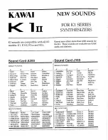
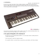
K1
Brand: Kawai Pages: 6
CS-80
Brand: Yamaha Pages: 13

ANTIPHON
Brand: Dreadbox Pages: 21

K3
Brand: Kawai Pages: 35
K3
Brand: Kawai Pages: 19

Polaris
Brand: Fender Pages: 68
120X
Brand: dbx Pages: 12
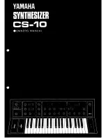
CS-10
Brand: Yamaha Pages: 19

DX100
Brand: Yamaha Pages: 36
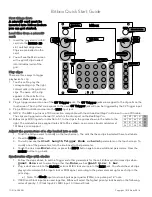
Bitbox
Brand: 1010 Music Pages: 2

Spherical Wavetable Navigator
Brand: 4ms Company Pages: 4
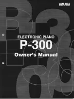
P-300
Brand: Yamaha Pages: 61
WAVE
Brand: P.P.G. Pages: 4

Virus TI
Brand: Access Pages: 186
9308
Brand: Paia Pages: 6

RM
Brand: Daedalus Pages: 40
proteus 2000
Brand: E-Mu Pages: 10

CAT
Brand: Octave Pages: 38


