
MTX3
DCH8
40 m
1 m
60 m
80 m
100 m
41 m
61 m
81 m
101 m
100 m
130 m
160 m
190 m
101 m
131 m
161 m
191 m = Max.
Termination
= ON
1
2
3
MTX3
DCH8
1 m
100 m
0.5 m
90 m
Termination
= ON
50 m
MTX3
DCH8
50 m
50 m
50 m
60 m
30 m
20 m
40 m
20 m
40 m
Termination= ON
20 m
40 m
20 m
40 m
191.5 m = Max.
151.5 m
150 m
120 m
100 m
170 m
150 m
130 m
180 m
200 m = Max.
–2–
TO HOST:
Connect the [DCP] connector of
the host device or the DCH8
connected to the host.
1 - 8:
Connect the control
panels or another
DCH8.
• This device contains no user-serviceable parts. Do
not open the device or attempt to disassemble the
internal parts or modify them in any way. If it should
appear to be malfunctioning, discontinue use
immediately and have it inspected by qualified
Yamaha service personnel.
WARNING
Do not open
• Do not place the device in a location where it may
come into contact with corrosive gases or salt air.
Doing so may result in malfunction.
• Before moving the device, remove all connected
cables.
Location
• Do not rest your weight on the device or place heavy
objects on it, and avoid use excessive force on the
buttons, switches or connectors to prevent injuries.
Handling caution
• Do not place any burning items or open flames near
the device, since they may cause a fire.
Fire warning
NOTICE
To avoid the possibility of malfunction/ damage to the
product, damage to data, or damage to other property,
follow the notices below.
Handling and maintenance
• Do not expose the device to excessive dust or
vibration, or extreme cold or heat (such as in direct
sunlight, near a heater, or in a car during the day), in
order to prevent the possibility of panel disfiguration,
unstable operation, or damage to the internal
components.
• Do not place vinyl, plastic or rubber objects on the
device, since this might discolor the panel.
• When cleaning the device, use a dry and soft cloth.
Do not use paint thinners, solvents, cleaning fluids, or
chemical-impregnated wiping cloths.
• Condensation can occur in the device due to rapid,
drastic changes in ambient temperature—when the
device is moved from one location to another, or air
conditioning is turned on or off, for example. Using
the device while condensation is present can cause
damage. If there is reason to believe that
condensation might have occurred, leave the device
for several hours until the condensation has
completely dried out.
• Do not expose the device to rain, use it near water or
in damp or wet conditions. If any liquid such as water
seeps into the device, unplug the cables. Then have
the device inspected by qualified Yamaha service
personnel.
• If this device should be dropped or damaged,
immediately disconnect cables from this device, and
have the device inspected by qualified Yamaha
service personnel.
• Avoid inserting or dropping foreign objects (paper,
plastic, metal, etc.) into any gaps or openings on the
device (panel, etc.) If this happens, immediately turn
off the power of the connected devices, unplug the
power cord from the AC outlet, and have the device
inspected by qualified Yamaha service personnel.
• Avoid pulling the cables connected to the devices,
etc. to prevent injuries.
About this manual
• The illustrations as shown in this manual are for
instructional purposes only.
• The company names and product names in this
manual are the trademarks or registered trademarks
of their respective companies.
PA_en_6
Manual Development Department
© 2016 Yamaha Corporation
Published 01/2016 MW??*.*-**A0
Printed in China
ZT34960
Main Features
• Divides the control line from host devices such
as the Yamaha MTX/MRX series into up to 8
lines.
• Allows for a flexible system structure, with a
combination of star connections and daisy
chain connections as a repeater between the
host device and the control panels.
• Supports various ways of installation with screw
holes equipped for mount fittings on the side
and in the rear.
Accessories
(Please make sure they are included.)
• Mount fittings x 2
• Mount fitting screws x 4
• Owner's Manual (this document)
Supported Devices
Host devices
MTX3, MTX5-D, MRX7-D, MA2120, PA2120
Control Panels
DCP1V4S, DCP4S, DCP4V4S
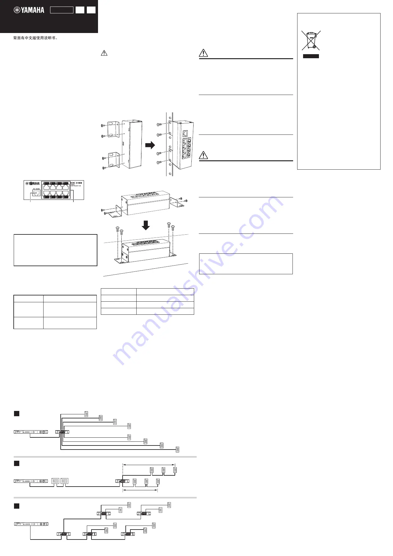
Part Names and Basic Connection
Horizontal Installation
Vertical Installation
General Specifications
Operating temperature 0°C to +40°C
Storage temperature
-20°C to +60°C
Dimensions
132 mm (W) x 42 mm (H) x 44 mm (D)
Net weight
0.24 kg
DCH8 Owner’s Manual
EN
ZH
(As of Jan. 2016)
Installation Method
Connection Example
The contents of this manual apply to the latest specifications
as of the printing date. To obtain the latest manual, access the
Yamaha website then download the manual file.
PRECAUTIONS
PLEASE READ CAREFULLY BEFORE
PROCEEDING
Please keep this manual in a safe place for future
reference.
Always follow the basic precautions listed below to
avoid the possibility of serious injury or even death
from electrical shock, short-circuiting, damages, fire
or other hazards. These precautions include, but are
not limited to, the following:
CAUTION
Always follow the basic precautions listed below to
avoid the possibility of physical injury to you or
others, or damage to the device or other property.
These precautions include, but are not limited to,
the following:
Yamaha cannot be held responsible for damage
caused by improper use or modifications to the
device.
Network Topology and Connection
Distance
Network topology
You can combine star connections and daisy
chain connections.
Connection distance
The distance between the host device and the
most distant controller should be within 200
meters.
NOTE
Jacks from 1 to 8 all have the same function.
Caution for Connecting the Device
• Do not connect any unsupported devices (for
example computers, routers, and the like).
• Do not leave attached any cables that are not
connected to a device.
When mounting the device on a rack, make sure you
secure the device with mount fittings on both the upper
and lower sides.
For example, do not fasten only the fittings on one side
when installing the device horizontally on the rack.
If the weight of the device suddenly pushes on the top
part of the rack, the device may break or cause you to
sustain injuries.
NOTE
The screws for mounting the device onto the rack are not
included with the product. Obtain the screws separately.
CAUTION
Information for Users on Collection
and Disposal of Old Equipment
This symbol on the products, pack-
aging, and/or accompanying docu-
ments means that used electrical
and electronic products should not
be mixed with general household
waste.
For proper treatment, recovery and
recycling of old products, please
take them to applicable collection points, in accor-
dance with your national legislation and the Direc-
tives 2002/96/EC.
By disposing of these products correctly, you will
help to save valuable resources and prevent any
potential negative effects on human health and the
environment which could otherwise arise from inap-
propriate waste handling.
For more information about collection and recycling
of old products, please contact your local munici-
pality, your waste disposal service or the point of
sale where you purchased the items.
[For business users in the European Union]
If you wish to discard electrical and electronic
equipment, please contact your dealer or supplier
for further information.
[Information on Disposal in other Countries
outside the European Union]
This symbol is only valid in the European Union. If
you wish to discard these items, please contact
your local authorities or dealer and ask for the
correct method of disposal.
(weee_eu_en_01)
Termination Settings
Turn the termination setting on only for the control
panel that is the most distant from the host device.
If you connect multiple controllers at the same
distance, turn the termination setting on only for one of
them.
NOTE
More details for termination and ID settings for control panels,
refer to the Owner’s Manual for the control panel.
Host device
Max. number of connections
MTX3
MTX5-D
MRX7-D
MA2120
PA2120
DCH8= 7
Control panel=8
DCH8=1
Control panel=2
Maximum Number of Device
Connections per Host
DIGITAL CONTROLLER HUB


