background image

IMPORTANT!
Please record the serial number of this
unit in the space below.

Model:
Serial No.:

The serial number is located on the rear
of the unit.
Retain this Owner’s Manual in a safe
place for future reference.

WARNING
TO REDUCE THE RISK OF FIRE OR
ELECTRIC SHOCK, DO NOT EXPOSE
THIS UNIT TO RAIN OR MOISTURE.

RISK OF ELECTRIC SHOCK

DO NOT OPEN

CAUTION:  TO REDUCE THE RISK OF

ELECTRIC SHOCK, DO NOT REMOVE

COVER (OR BACK), NO USER-SERVICEABLE

PARTS INSIDE, REFER SERVICING TO

QUALIFIED SERVICE PERSONNEL.

The lightning flash with arrowhead
symbol, within an equilateral triangle,
is intended to alert you to the
presence of uninsulated “dangerous
voltage” within the product’s
enclosure that may be of sufficient
magnitude to constitute a risk of
electric shock to persons.

The exclamation point within an
equilateral triangle is intended to alert
you to the presence of important
operating and maintenance
(servicing)  instructions in the
literature accompanying the
appliance.

• Explanation of Graphical Symbols

CAUTION

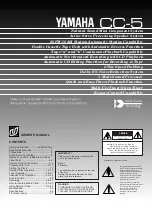
Natural Sound Mini Component System

Active Servo Processing Speaker System

20 FM/10 AM Station Automatic Storing Capability

Double Cassette Tape Deck with Automatic Reverse Function

Tape “a” and “b” Continuous Playback Capability

Automatic Synchronized Recording with CD Playback

Automatic CD Editing Function for Recording to Tape

2-Way Speed Dubbing

Dolby B/C Noise Reduction System

3-Mode Sound Processor

Quick and Easy Direct Playback Function

Multi-Use Timer/Sleep Timer

Remote Control Capability

CC-5

Thank you for selecting this YAMAHA mini component system.
This system is composed of TCD-CC5, A-CC5, K-CC5 and NS-CC5.

OWNER’S MANUAL

Active Servo

Technology

CONTENTS

Safety Instructions ..............Inside Front Cover
Supplied Accessories .............................. 1
Precautions ..............................................2
Active Servo Technology .........................3
Names of Controls, Indicators and Rear
Panel Parts  ..........................................4–6
Remote Control Transmitter .................7–9
Preparation for Use ..........................10–11
Setting the Clock ....................................12
Compact Disc Operation ..................12–18
Tuner Operation ...............................19–21
Cassette Tape Operation .................22–24
Sound Control.........................................25
Recording .........................................26–30
How to Use the Built-in Timer...........31–33
Using External Units .........................34–35
Maintenance ...........................................35
Specifications .........................................36
Troubleshooting......................................37

Summary of Contents for CC-5

Page 1: ...ation of Graphical Symbols CAUTION Natural Sound Mini Component System Active Servo Processing Speaker System 20 FM 10 AM Station Automatic Storing Capability Double Cassette Tape Deck with Automatic Reverse Function Tape a and b Continuous Playback Capability Automatic Synchronized Recording with CD Playback Automatic CD Editing Function for Recording to Tape 2 Way Speed Dubbing Dolby B C Noise R...

Page 2: ...r B Objects have fallen or liquid has been spilled into the unit or C The unit has been exposed to rain or D The unit does not appear to operate normally or exhibits a marked change in performance or E The unit has been dropped or the cabinet damaged 16 Servicing The user should not attempt to service the unit beyond those means described in the operating instructions All other servicing should be...

Page 3: ...es not guarantee that interference will not occur in all installations If this product is found to be the source of interference which can be determined by turning the unit OFF and ON please try to eliminate the problem by using one of the following measures Relocate either this product or the device that is being affected by the interference Utilize power outlets that are on different branch circ...

Page 4: ... Sudden temperature changes and storage or operation in an extremely humid environment may cause condensation inside the cabinet Condensation can cause the unit to malfunction Follow the procedure below to eliminate condensation CD pickup Leave the power on with no disc in the unit until normal playback is possible about 1 hour Tape head Leave the power on with no cassette in the unit until normal...

Page 5: ...s resolved through the employment of a design in which the amplifier functions to supply the signals If the electrical resistance of the voice coil is reduced to zero the movement of the speaker unit would become linear with respect to signal voltage and to accomplish this a special negative impedance output drive amplifier for subtracting output impedance of the amplifier is used By employing neg...

Page 6: ...utton 16 Stop Button 17 Play Button 18 Disc Table 19 Open Close Button 20 EDIT Button 21 Skip Buttons 22 Auto Tape Edit Buttons Tuner Timer Section 23 Preset Number Indicator 24 Band Indicator 25 Station Frequency Indicator 26 MEMORY Indicator 27 AUTO ST Indicator 28 FM STEREO Indicator 29 TIMER Set Indicator 30 ON TIME Indicator 31 SLEEP Indicator 32 AUTO MEMORY Button 33 BAND Selector Button 34 ...

Page 7: ...mpartment 53 EJECT Button 54 Fast Wind Button 55 Play Button and Indicator 56 Stop Button 57 Play Button and Indicator 58 Fast Wind Button Controls for Tape b 59 Fast Wind Button 60 Play Button and Indicator 61 Stop Button 62 Play Button and Indicator 63 Fast Wind Button 64 EJECT Button 65 Tape b Cassette Compartment Common Controls for Tape a and b 66 REVERSE MODE Switch 67 DOLBY NR Switch 68 DUB...

Page 8: ...supply lead of this unit from the AC outlet Rear Panel of Amplifier Section 5 System Control Sockets 6 SPEAKERS Terminals 7 DAT Terminals 8 PHONO Terminals and GND Terminal 9 AUX Terminals 10 VOLTAGE SELECTOR General model only 11 AC Supply Lead VOLTAGE SELECTOR General model only The voltage selector on the rear panel of this unit must be set for your local main voltage BEFORE plugging into the A...

Page 9: ...lose Button 11 Skip Buttons 12 CD Call Button 13 Play Button 14 Pause Button Tuner Control Buttons 15 Tuning Up Down Buttons 16 BAND Selector Button 17 TUNER Call Button REMOTE CONTROL TRANSMITTER E 7 1 2 3 4 5 6 7 8 9 0 CLEAR CALL TIME PROG REPEAT CD BAND TUNER HALL JAZZ CLUB ROCK CNCT OFF POWER AUX DAT VOLUME TAPE b a 10 BAND TUNER HALL JAZZ CLUB ROCK CNCT OFF POWER AUX DAT VOLUME TAPE b a 1 2 3...

Page 10: ...on 30 POWER Switch 31 AUX Call Button 32 DAT Call Button or PHONO Call Button for U K Australia and Europe models 33 Sound Processor Program Selectors 34 Sound Processor OFF Button 35 VOLUME Down Up Buttons REMOTE CONTROL TRANSMITTER E 8 Tape b Tape a BAND TUNER HALL JAZZ CLUB ROCK CNCT OFF TAPE b a REPEAT CD BAND TUNER HALL JAZZ CLUB ROCK CNCT OFF POWER AUX DAT VOLUME TAPE b a 18 24 19 20 21 22 2...

Page 11: ...ies Proper use of the remote control transmitter Aim within the range of 30 with no obstacles the remote control transmitter at the remote control sensor and operate as shown Notes concerning use Replace the batteries if control distance decreases or operation becomes unstable Periodically clean the transmitter window on the remote control transmitter and the sensor on the main unit with a soft cl...

Page 12: ...e to the corresponding terminals Position the MW LW AM loop antenna for optimum reception Place the MW LW AM loop antenna on a shelf etc or install it on the rack or wall with screws not supplied Notes When static is still heard even after adjusting the position of the MW LW AM loop antenna try reversing the connection right to left Do not place the MW LW AM loop antenna on the unit It will result...

Page 13: ...connect these SPEAKERS terminals to speakers other than the provided speaker system System connection Connect the red connector to the red socket Connect the white connector to the white socket Connect the black connector to the black socket How to disconnect the system connector Grasp both sides of the connector to disconnect the connector Connecting the AC supply lead After connecting the speake...

Page 14: ...pply is resumed the clock display will flash on and off to indicate that the time must be reset Care of compact discs Compact discs are fairly resistant to damage however mistracking can occur due to an accumulation of dirt on the disc surface Follow the guidelines below for maximum enjoyment from your CD collection and player Do not write on either side of the disc particularly the non label side...

Page 15: ... track number will go out Direct playback If a compact disc is already in the disc table just press the play button to automatically turn on the power and start playback To interrupt playback 1 1 Press the pause button The indicator will light up 2 2 Press the play button to resume playback from the same point To stop playback Press the stop button To switch the unit off after use Set the unit to ...

Page 16: ...op after 4 seconds even if the open close button is not pressed At this time Er 0 00 appears in the display If the power fails while the table is open wait until the power supply returns or gently push the table manually to close it The temperature range for playing compact discs is recommended to be 5 C 41 F 35 C 95 F Direct selection play By using the track number input buttons on the remote con...

Page 17: ... or backward from any point on the disc However it will not move forward during playback of the final track COMPACT DISC OPERATION 1 2 3 4 5 6 7 8 9 0 CLEAR CALL TIME PROG REPEAT CD BAND TUNER HALL JAZZ CLUB ROCK CNCT OFF POWER AUX DAT VOLUME TAPE b a 10 Manual search 1 Begin playback 2 Press and hold the button to advance play rapidly and the button to reverse play rapidly The sound can be heard ...

Page 18: ...rogrammed selections Notes It is also possible to program a sequence of tracks while looking at the list of tracks on the surface of the disc before closing the disc table During playback or pause programming is not possible To check the program data Press the CALL button while the disc is stopped to review the order of the programmed sequence before playback begins While the playback order and tr...

Page 19: ... Program a sequence of up to 20 tracks Refer to the Program play on the previous page for the programming method 2 2 Press the REPEAT button The REPEAT indicator will light up 3 3 Press the play button To repeat a single track 1 1 Program a single track Refer to the Program play on the previous page for the programming method 2 2 Press the REPEAT button The REPEAT indicator will light up 3 3 Press...

Page 20: ... The elapsed play time for each track will be displayed 8 seconds have passed since the beginning of the second track The remaining play time for the current track will be displayed 2 minutes and 58 seconds remain till the end of the second track The total play time up to the current track will be displayed 8 minutes and 16 seconds have passed since the beginning of the first track The total remai...

Page 21: ...t station which was stored last into memory If fewer than 20 FM stations or 10 AM LW or MW stations have been stored in memory auto scan memory will stop at the highest frequency and this unit will turn into receiving mode If auto scan memory is performed again though broadcasting stations have been already stored the previous contents are erased Note The auto scan memory function may be affected ...

Page 22: ...t station Manual tuning Press the TUNING or button repeatedly to adjust the frequency display to the frequency of the desired station 3 Press the MEMORY button so that the display s MEMORY indicator flashes 4 Press the TUNER PRESET or button until the preset number to be programmed appears in the display 5 Press the MEMORY button to store that station in the selected station preset number memory 2...

Page 23: ...ation noise as well as weak stations are suppressed Only in the FM monaural mode weak and noisy stations can be received To switch the unit off after use Set the unit to the STANDBY mode by pressing the POWER switch The indicators will go off except for the STANDBY indicator and the current time display Notes Memory recalls the last station received even after changing the BAND selector button or ...

Page 24: ...g cannot be done on metal tapes only When covering erasure prevention tab holes do not cover the chrome and metal detection holes Otherwise the deck will treat tape as normal tape Do not press the EJECT button during playback or recording Tape a or tape b playback 1 Select the TAPE position 2 Open the tape a or tape b cassette compartment by pushing the EJECT button 3 Load the cassette into the ta...

Page 25: ...essing the POWER switch The indicators will go off except for the STANDBY indicator and the current time display Winding the tape 1 First press the stop button 2 Next press the or button to wind the tape 3 Press the stop button to stop Searching for the beginning of a desired selection Carry out the following operation during playback to find the beginning of a desired selection on the tape To lis...

Page 26: ...een equipped with a newly developed Dolby C noise reduction system in addition to its conventional Dolby B NR Either type of noise reduction may be selected with the switch provided Dolby B NR has a noise reduction effect of about 10 dB in the high frequency range The corresponding figure with Dolby C NR is about 20 dB but this is over the entire range where the human ear is most sensitive to nois...

Page 27: ... or counter clockwise to decrease the high frequency response Sound processor If desired select your favorite sound processor program by pressing the SOUND PROCESSOR button The indicator below the name of the selected program illuminates No illumination shows that the sound processor is off For each program feature refer to the following explanation BALANCE L R BASS TREBLE The ideal program for li...

Page 28: ...d 2 Load a tape into the tape b cassette compartment Wind past the beginning part of the tape on which recording can not be performed 3 When recording with the Dolby NR system set the DOLBY NR switch to B or C if not set it to OFF For selection of the Dolby B or C position refer to the Dolby B and C Type Noise Reduction on page 24 4 Set the REVERSE MODE switch to to record on only one side or to f...

Page 29: ...ter about 2 seconds Note The CD Synchronised Recording System will function even when the CD player is set to the program play or random play mode In this case when more than 2 seconds elapse between tracks the tape will stop automatically and resume recording when the beginning of the next track is found When recording is continuously made on both sides of the tape Even if the recording for side ...

Page 30: ...r C90 Press the or button to adjust the time minute by minute Adjustable range is from C10 to C99 It is also possible to use the track number input buttons on the remote control to set the tape length For a tape length of C30 press the 10 10 10 and 0 Press each button within 3 seconds after the previous one has been pressed 7 Press the EDIT button Tracks on the CD are automatically divided between...

Page 31: ...pe 1 Select the TAPE position 2 Load a prerecorded tape into the tape a cassette compartment Insert a blank tape into the tape b cassette compartment 3 Set the REVERSE MODE switch to to record on only one side or to for continuous recording on both sides 4 Press the DUBBING button Press NORMAL to dub at normal speed and HIGH to dub at about twice the normal speed Dubbing will begin from side A To ...

Page 32: ... button The indicator beside the REC button lights up and the play indicators flash 6 Press the play button to record side A or the play button to record side B For continuous recording of both sides begin on side A Recording stops automatically at the end of side B To stop recording temporarily 1 1 Press the PAUSE button 2 2 To resume recording press the play button whose indicator is flashing To...

Page 33: ...ition The tuner turns on automatically at the desired time To play a compact disc 1 Select the CD position 2 Load the disc 3 Perform steps 3 6 of the To listen to the tuner section CD playback starts automatically at the desired time To playback a cassette tape 1 Select the TAPE position 2 Load a recorded cassette tape into the tape a or tape b cassette compartment If tapes are loaded in both the ...

Page 34: ... To set the desired volume level for listening to a source with the timer use the VOLUME control before setting the timer Except when you perform recording with the timer be sure to set the TIMER switch to the PLAY position To confirm the timer time setting Press the DISPLAY button To cancel the timer operation Press the POWER switch The TIMER indicator will go out Unless the AC supply lead is unp...

Page 35: ...s on press the SLEEP button repeatedly until the desired time to replace appears The display will change as described below If the current time is selected the power is turned off after 2 seconds To stop the sleep timer operation Press the POWER switch The SLEEP indicator will go out Using the timer and the sleep timer at the same time 1 Prepare timer playback See page 31 2 Press the SLEEP button ...

Page 36: ...onnect the output lead of a DAT or another input source red right channel white left channel 2 Select the DAT position with the INPUT selector 3 Operate the unit connected to the DAT inputs 4 Start recording with this unit if so desired See page 30 Turntable PHONO U K Australia and Europe models 1 Connect the output lead of a turntable red right channel white left channel 2 Connect the GND lead of...

Page 37: ...cotton swab moistened with commercial head pinch roller cleaner or isopropyl alcohol After long use the deck s heads and capstans may become magnetised causing poor sound Demagnetise these parts once every 30 hours of playing recording time by using a commercial tape head demagnetiser Read the demagnetiser s instructions carefully before use External care Periodically wipe the cabinet with a soft ...

Page 38: ...filter Frequency response 20 20 000 Hz Wow and flutter Unmeasurable less than 0 001 W peak Amplifier section Power Supply U S A and Canada models AC 120V 60 Hz Australia and U K models AC 240V 50 Hz Europe model AC 230V 50 Hz General model AC 110 120 220 240V 60 50 Hz Power consumption U S A model only 120 W Canada model only 165 W Australia Europe U K and General models 125 W Continuous power out...

Page 39: ...rical appliance Antenna input is too weak due to obstructions or excessive distance from broadcasting station Insufficient antenna input Preset memory has been erased Interference from source such as lightning flourescent lights electric motors or thermostat of nearby electrical appliance TV or microprocessor is being used nearby Radio signal is weak or antenna is not properly connected Current ti...

Page 40: ...25462 RELLINGEN BEI HAMBURG F R OF GERMANY YAMAHA ELECTRONIQUE FRANCE S A RUE AMBROISE CROIZAT BP70 CROISSY BEAUBOURG 77312 MARNE LA VALLEE CEDEX02 FRANCE YAMAHA ELECTRONICS UK LTD YAMAHA HOUSE 200 RICKMANSWORTH ROAD WATFORD HERTS WD1 7JS ENGLAND YAMAHA SCANDINAVIA A B J A WETTERGRENS GATA 1 BOX 30053 400 43 VÄSTRA FRÖLUNDA SWEDEN YAMAHA MUSIC AUSTRALIA PTY LTD 17 33 MARKET ST SOUTH MELBOURNE 3205...

Reviews: