Yamaha AVR-S80, Owner'S Manual
The Yamaha AVR-S80 Owner's Manual is available for free download on our website. This comprehensive manual provides detailed instructions and information about the product, ensuring users have a hassle-free experience. Visit manualshive.com to access your free manual and unlock the full potential of your Yamaha AVR-S80.
Share
Download


Reviews:
No comments
Related manuals for AVR-S80
8000 Series
Brand: KEF Pages: 13
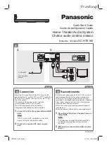
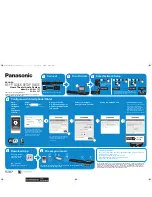
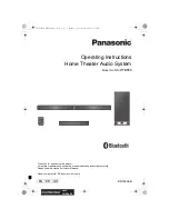
SC-HTE180
Brand: Panasonic Pages: 2
VieraLink SC-ALL30T
Brand: Panasonic Pages: 12
SC-HTB550
Brand: Panasonic Pages: 36
SC-HTB570
Brand: Panasonic Pages: 2
SC-BT205
Brand: Panasonic Pages: 2
SC-HTB20
Brand: Panasonic Pages: 2
SCBT730 - BLU RAY HOME THEATER SYSTEM
Brand: Panasonic Pages: 2

SC-ALL70T
Brand: Panasonic Pages: 12
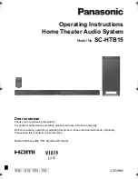
SC-HTB15
Brand: Panasonic Pages: 32
SC-HTB8
Brand: Panasonic Pages: 24
SC-HTB20
Brand: Panasonic Pages: 32
SC-HTB400
Brand: Panasonic Pages: 32
SC-BTT500W
Brand: Panasonic Pages: 52
SC-BTT270
Brand: Panasonic Pages: 52
SC-HTB880
Brand: Panasonic Pages: 2
SC-HTB770
Brand: Panasonic Pages: 44
SC-HTE80
Brand: Panasonic Pages: 36


