Yamaha AR210, Owner'S/Operator'S Manual
The Yamaha AR210 Owner's/Operator's Manual is a comprehensive guide for users of the Yamaha AR210 boat. This manual is available for free download from our website, providing detailed instructions, maintenance tips, and essential information to ensure a safe and enjoyable experience on the water with your Yamaha AR210.
Share
Download


Reviews:
No comments
Related manuals for AR210
F-22
Brand: FARRIER MARINE Pages: 52
37
Brand: Tayana Pages: 85
26
Brand: MACGREGOR Pages: 22
8
Brand: Walker Bay Pages: 16
110
Brand: J Pages: 30
42
Brand: Lagoon Pages: 122
64
Brand: Jeanneau Pages: 80
380
Brand: Lagoon Pages: 114
3500
Brand: Tartan Pages: 42
Express
Brand: Malibukayaks Pages: 19
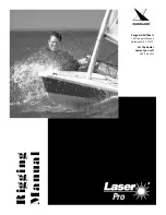
Laser Pro
Brand: Vanguard Sailboats Pages: 8

Sport
Brand: TAKACAT Pages: 12
Fun
Brand: Jeanneau Pages: 15
RX1
Brand: NEILPRYDE Pages: 4
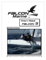
F18
Brand: Falcon Pages: 41
Heron
Brand: Feathercraft Pages: 23
Wisper
Brand: Feathercraft Pages: 23
53
Brand: Jeanneau Pages: 58


