Yamaha 2006 XF50W, Service Manual
The Yamaha 2006 XF50W Service Manual is a comprehensive guide for maintaining and repairing your Yamaha XF50W. This user manual provides detailed instructions, diagrams, and troubleshooting tips to ensure you can easily service your scooter. Download it for free from manualshive.com and keep your Yamaha XF50W in top condition.
Share
Download


Reviews:
No comments
Related manuals for 2006 XF50W
7 Series
Brand: C.T.M. Pages: 17

FLYER
Brand: Y Volution Pages: 36
2 Series
Brand: C.T.M. Pages: 17
E200 Series
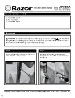
Brand: Razor Pages: 12
318
Brand: Rascal Pages: 39
99
Brand: LaScoota Pages: 10
E300 Series
Brand: Razor Pages: 2
E300 Series
Brand: Razor Pages: 2
E300 Series
Brand: Razor Pages: 31
5 series
Brand: C.T.M. Pages: 18
SLATE
Brand: Jetson Pages: 20
Pro 8
Brand: W-Tec Pages: 19
SC7000
Brand: Youin Pages: 80
V50
Brand: NAVEE Pages: 44
C25
Brand: Razor Pages: 2
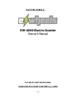
EW-1000
Brand: E-Wheels Pages: 14
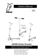
GS300
Brand: JDbug Pages: 8
Focus
Brand: KEEWAY Pages: 115


