background image

2004

YP400(S)

5RU1-AE1

SERVICE MANUAL

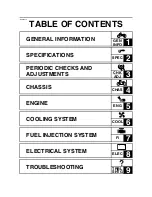
Summary of Contents for 2004 YP400

Page 1: ...2004 YP400 S 5RU1 AE1 SERVICE MANUAL ...

Page 2: ......

Page 3: ...0 S 2004 SERVICE MANUAL 2003 by Yamaha Motor Co Ltd First edition December 2003 All rights reserved Any reproduction or unauthorized use without the written permission of Yamaha Motor Co Ltd is expressly prohibited ...

Page 4: ... models Modifications and significant changes in specifications or procedures will be forwarded to all authorized Yamaha deal ers and will appear in future editions of this manual where applicable NOTE _ Designs and specifications are subject to change without notice EAS00005 IMPORTANT MANUAL INFORMATION Particularly important information is distinguished in this manual by the following The Safety...

Page 5: ...of each page except in Chapter 3 PERIODIC CHECKS AND ADJUSTMENTS where the sub section title s appears 3 Sub section titles appear in smaller print than the section title 4 To help identify parts and clarify procedure steps there are exploded diagrams at the start of each removal and disassembly section 5 Numbers are given in the order of the jobs in the exploded diagram A circled number indicates...

Page 6: ...g fluid B Lubricant C Special tool D Tightening torque E Wear limit clearance F Engine speed G Electrical data Symbols H to M in the exploded diagrams indicate the types of lubricants and lubrication points H Engine oil I Gear oil J Molybdenum disulfide oil K Wheel bearing grease L Lithium soap based grease M Molybdenum disulfide grease Symbols N to O in the exploded diagrams indicate the followin...

Page 7: ...S GENERAL INFORMATION GEN INFO 1 SPECIFICATIONS SPEC 2 PERIODIC CHECKS AND ADJUSTMENTS CHK ADJ 3 CHASSIS CHAS 4 ENGINE ENG 5 COOLING SYSTEM COOL 6 FUEL INJECTION SYSTEM FI 7 ELECTRICAL SYSTEM ELEC 8 TROUBLESHOOTING TRBL SHTG 9 ...

Page 8: ......

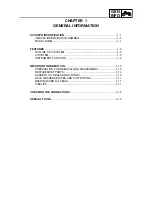
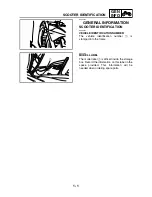
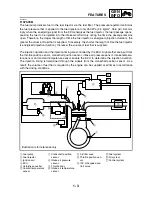
Page 9: ...GEN INFO 1 ...

Page 10: ... 2 OUTLINE OF FI SYSTEM 1 2 FI SYSTEM 1 3 INSTRUMENT FUNCTION 1 4 IMPORTANT INFORMATION 1 10 PREPARATION FOR REMOVAL AND DISASSEMBLY 1 10 REPLACEMENT PARTS 1 10 GASKETS OIL SEALS AND O RINGS 1 10 LOCK WASHERS PLATES AND COTTER PINS 1 11 BEARINGS AND OIL SEALS 1 11 CIRCLIPS 1 11 CHECKING THE CONNECTIONS 1 12 SPECIAL TOOLS 1 13 ...

Page 11: ...GEN INFO ...

Page 12: ...CATION NUMBER The vehicle identification number 1 is stamped into the frame 1 EAS00018 MODEL LABEL The model label 1 is affixed inside the storage box Record the information on this label in the space provided This information will be needed when ordering spare parts 1 SCOOTER IDENTIFICATION ...

Page 13: ...he engine to deliver more performance and cleaner exhaust gases increase it becomes necessary to control the air fuel ratio in a more precise and finely tuned man ner To accommodate this need this model has adopted an electronically controlled fuel injection FI system in place of the conventional carburetor system This system can achieve an optimum air fuel ratio required by the engine at all time...

Page 14: ...ed The injection duration and the injection timing are controlled by the ECU Signals that are input from the throttle position sensor crankshaft position sensor intake air pressure sensor intake tempera ture sensor and coolant temperature sensor enable the ECU to determine the injection duration The injection timing is determined through the signals from the crankshaft position sensor As a result ...

Page 15: ...s which show the distance traveled since they were last set to zero a fuel reserve tripmeter which shows the distance traveled since the bottom segment of the fuel meter and fuel level warning symbol started flashing a self diagnosis device a clock an ambient temperature display an oil change indicator a V belt replacement indicator NOTE Be sure to turn the key to ON before using the SELECT and RE...

Page 16: ...Fuel reserve tripmeter To reset a tripmeter select it by pushing the SELECT button and then push the RESET button for at least one second If you do not reset the fuel reserve tripmeter manually it will reset itself automatically and the display will return to the prior mode after refueling and traveling 5 km 3 mi 1 Fuel meter With the key in the ON position the fuel meter indicates the amount of f...

Page 17: ...ne oil reset the oil change indicator Refer to To reset the oil change indicator If the engine oil is changed before the oil change indicator comes on i e before the periodic oil change interval has been reached the indicator must be reset after the oil change for the next periodic oil change to be indicated at the correct time The electrical circuit of the indicator can be checked according to th...

Page 18: ...ashes every 20 000 km 12 000 mi when the V belt needs to be replaced The electrical circuit of the indicator can be checked according to the following procedure 1 Turn the key to ON and make sure that the engine stop switch is set to 2 If the indicator does not come on check the electrical circuit Refer to SIGNALING SYSTEM in chapter 8 To reset the V belt replacement indicator 1 Turn the key to ON...

Page 19: ...icator light will flash and then the multifunction dis play will indicate a two digit error code e g 51 52 53 when the key is turned to ON NOTE If the multifunction display indicates error code 52 this could be caused by transponder inter ference If this error appears try the following 1 Use the code re registering key to start the engine NOTE Make sure there are no other immobilizer keys close to...

Page 20: ...e ambient temperature from 10 C to 50 C in 1 C increments The temperature displayed may vary from the ambient temperature Pushing the RESET button for at least two seconds switches the ambient temperature display to the clock dis play When the ambient temperature falls below 10 0 C 10 0 C is displayed When the ambient temperature climbs above 50 0 C 50 0 is displayed NOTE If C is displayed or 50 0...

Page 21: ...n all of the parts and place them in trays in the order of dis assembly This will speed up assembly and allow for the correct installation of all parts 5 Keep all parts away from any source of fire EAS00021 REPLACEMENT PARTS Use only genuine Yamaha parts for all replacements Use oil and grease recom mended by Yamaha for all lubrication jobs Other brands may be similar in function and appearance bu...

Page 22: ... oil seals lubricate the oil seal lips with a light coat of lithium soap based grease Oil bearings liberally when installing if appro priate 1 Oil seal CAUTION _ Do not spin the bearing with compressed air because this will damage the bearing surfaces 2 Bearing EAS00025 CIRCLIPS Before reassembly check all circlips carefully and replace damaged or distorted circlips Always replace piston pin clips...

Page 23: ...nnect sev eral times 3 Check all connections Loose connection Connect properly NOTE _ If the pin 1 on the terminal is flattened bend it up 4 Connect lead coupler connector NOTE _ Make sure all connections are tight 5 Check continuity with the pocket tester NOTE _ If there is no continuity clean the terminals When checking the wire harness perform steps 1 to 3 As a quick remedy use a contact revita...

Page 24: ...llustration 90890 01235 YU 01235 Rotor holding tool This tool is used to hold the primary fixed sheave and clutch shoe assembly 90890 01268 YU 01268 Ring nut wrench This tool is used to loosen or tighten the steering ring nuts 90890 01304 YU 01304 Piston pin puller set This tool is used to remove the piston pins Radiator cap tester 90890 01325 YU 24460 01 Radiator cap tester adapter 90890 01352 YU...

Page 25: ...hen installing the secondary sliding sheave 90890 01403 YU A9472 Steering nut wrench This tool is used to loosen or tighten the steering ring nuts Pivot shaft wrench 90890 01471 YM 01471 Pivot shaft wrench adapter 90890 01476 Pivot shaft wrench Pivot shaft wrench adapter These tools are used to tighten the sub frame adjusting bolt 90890 01701 YS 01880 A Sheave holder This tool is used to hold the ...

Page 26: ...ttachment These tools are used to remove or install the valve assemblies Middle driven shaft bearing driver 90890 04058 YM 04058 Mechanical seal installer 90890 04145 Middle driven shaft bearing driver Mechanical seal installer These tools are used to install the water pump seal 90890 04097 YM 04097 Valve guide remover 5 mm This tool is used to remove or install the valve guides 90890 04098 YM 040...

Page 27: ...ession spring when removing or installing the clutch shoe assembly nut 90890 04146 Plane bearing installer remover This tool is used to install or remove the crankshaft journal bearings 90890 06754 YM 34487 Ignition checker This tool is used to check the ignition sys tem components Bond 90890 85505 Sealant ACC 11001 05 01 Yamaha bond No 1215 Sealant Quick Gasket This bond is used to seal two matin...

Page 28: ...SPEC 2 ...

Page 29: ...VERSION TABLE 2 17 GENERAL TIGHTENING TORQUE SPECIFICATIONS 2 17 TIGHTENING TORQUES 2 18 ENGINE TIGHTENING TORQUES 2 18 CHASSIS TIGHTENING TORQUES 2 21 LUBRICATION POINTS AND LUBRICANT TYPES 2 23 ENGINE LUBRICATION POINTS AND LUBRICANT TYPES 2 23 CHASSIS LUBRICATION POINTS AND LUBRICANT TYPES 2 25 COOLING SYSTEM DIAGRAMS 2 26 CABLE ROUTING 2 28 ...

Page 30: ...SPEC ...

Page 31: ...th 2 230 mm 87 8 in Overall width 780 mm 30 7 in Overall height 1 380 mm 54 3 in Seat height 750 mm 29 5 in Wheelbase 1 565 mm 61 6 in Minimum ground clearance 120 mm 4 72 in Minimum turning radius 2 600 mm 102 4 in Weight Wet with oil and a full fuel tank 210 kg 463 lb Maximum load total of cargo rider passenger and accessories 198 kg 437 lb ...

Page 32: ...commended fuel Regular unleaded gasoline only EUR Unleaded gasoline only AUS Fuel tank capacity Total 14 L 3 08 Imp gal 3 70 US gal Engine oil Lubrication system Wet sump Recommended oil Refer to the chart for the engine oil grade Recommended engine oil grade API service SE SF SG type or higher Quantity Total amount 1 7 L 1 50 Imp qt 1 80 US qt Without oil filter element replace ment 1 5 L 1 32 Im...

Page 33: ...ng pressure 110 0 140 0 kPa 1 10 1 40 kg cm2 15 6 19 9 psi Radiator core Width 260 mm 10 24 in Height 148 mm 5 83 in Depth 24 mm 0 94 in Coolant reservoir Capacity 0 32 L 0 28 Imp qt 0 34 US qt Water pump Water pump type Single suction centrifugal pump Reduction ratio 37 22 25 37 1 136 Coolant temperature 90 100 C 194 212 F Starting system type Electric starter Electric fuel injection Type 1100 87...

Page 34: ...8 0 062 mm 0 0011 0 0024 in 0 08 mm 0 0031 in Intake camshaft lobe dimensions Measurement A 34 350 34 450 mm 1 352 1 356 in 34 250 mm 1 3484 in Measurement B 24 950 25 050 mm 0 982 0 986 in 24 850 mm 0 9783 in Exhaust camshaft lobe dimensions Measurement A 33 450 33 550 mm 1 317 1 321 in 33 350 mm 1 3130 in Measurement B 24 956 25 056 mm 0 982 0 986 in 24 856 mm 0 9786 in Maximum camshaft runout 0...

Page 35: ...94 0 0472 in 1 6 mm 0 06 in Exhaust 1 0 1 2 mm 0 0394 0 0472 in 1 6 mm 0 06 in Valve margin thickness D Intake 0 85 1 15 mm 0 0335 0 0453 in Exhaust 0 85 1 15 mm 0 0335 0 0453 in Valve stem diameter Intake 4 975 4 990 mm 0 1959 0 1965 in 4 945 mm 0 1947 in Exhaust 4 960 4 975 mm 0 1953 0 1959 in 4 930 mm 0 1941 in Valve guide inside diameter Intake 5 000 5 015 mm 0 1969 0 1974 in 5 053 mm 0 1989 i...

Page 36: ...t 46 45 mm 1 83 in 44 13 mm 1 74 in Installed length valve closed Intake 35 10 mm 1 38 in Exhaust 35 10 mm 1 38 in Compressed spring force installed Intake 160 5 184 7 N at 35 10 mm 16 37 18 83 kg at 35 10 mm 36 08 41 52 lb at 1 38 in Exhaust 160 5 184 7 N at 35 10 mm 16 37 18 83 kg at 35 10 mm 36 08 41 52 lb at 1 38 in Spring tilt Intake 2 0 mm 0 08 in Exhaust 2 0 mm 0 08 in Winding direction top...

Page 37: ...m 0 20 in Piston pin bore in the piston Diameter 20 004 20 015 mm 0 7876 0 7880 in 20 045 mm 0 7892 in Offset 1 0 mm 0 0394 in Offset direction Intake side Piston pin Outside diameter 19 991 20 000 mm 0 7870 0 7874 in 19 971 mm 0 7863 in Piston pin to piston pin bore clear ance 0 004 0 024 mm 0 0002 0 0010 in 0 074 mm 0 0029 in Piston rings Top ring Ring type Barrel Dimensions B T 1 00 2 70 mm 0 0...

Page 38: ...stalled 0 10 0 40 mm 0 0039 0 0157 in Ring side clearance 0 040 0 140 mm 0 0016 0 0055 in Crankshaft Width A 63 95 64 00 mm 2 518 2 520 in Maximum runout C 0 030 mm 0 0012 in Big end side clearance D 0 350 0 850 mm 0 0138 0 0335 in Big end radial clearance E 0 010 0 024 mm 0 0004 0 0009 in Crankshaft journal to crankshaft journal bearing clearance 0 030 0 077 mm 0 0012 0 0030 in 0 09 mm 0 0035 in ...

Page 39: ... V belt V belt width 30 mm 1 18 in 27 mm 1 06 in Transmission Primary reduction system Helical gear Primary reduction ratio 31 14 2 214 Secondary reduction system Helical gear Secondary reduction ratio 42 16 2 625 Clutch type Dry centrifugal automatic Transmission type V belt automatic Operation Centrifugal automatic type Single speed automatic 2 380 0 892 1 Air filter type Wet element Fuel pump P...

Page 40: ...runout 0 5 mm 0 02 in Wheel axle bending limit 0 25 mm 0 01 in Rear wheel Wheel type Cast wheel Rim Size 13 M C MT4 00 Material Aluminum Wheel travel 104 mm 4 09 in Wheel runout Maximum radial wheel runout 1 mm 0 04 in Maximum lateral wheel runout 0 5 mm 0 02 in Front tire Tire type Tubeless Size 120 80 14M C 58S Model manufacturer MB 67 IRC D305FL DUNLOP Tire pressure cold 0 90 kg 0 198 lb 200 kP...

Page 41: ...gf cm2 36 psi Minimum tire tread depth 1 6 mm 0 06 in Front brakes Brake type Single disc brake Operation Right hand operation Recommended fluid DOT 4 Brake discs Diameter thickness 267 5 mm 10 51 0 20 in Minimum thickness 4 5 mm 0 18 in Maximum deflection 0 15 mm 0 006 in Brake pad lining thickness 6 0 mm 0 24 in 0 8 mm 0 03 in Master cylinder inside diameter 14 0 mm 0 55 in Caliper cylinder insi...

Page 42: ...ing oil damper Front fork travel 120 mm 4 72 in Spring Free length 316 7 mm 12 47 in 310 4 mm 12 22 in Installed length 296 7 mm 11 68 in Spring rate K1 14 09 N mm 1 44 kg mm 80 45 lb in Spring rate K2 26 67 N mm 2 72 kg mm 152 28 lb in Spring stroke K1 0 90 mm 0 3 5433 in Spring stroke K2 90 120 mm 3 5433 4 7244 in Inner tube outer diameter 41 mm 1 61 in Inner tube bending limit 0 2 mm 0 01 in Op...

Page 43: ...5 12 in Spring Free length 306 6 mm 12 07 in 300 0 mm 11 81 in Installed length 290 6 mm 11 44 in Spring rate K1 6 22 N mm 0 63 kg mm 35 52 lb in Spring rate K2 11 80 N mm 1 20 kg mm 67 38 lb in Spring rate K3 22 50 N mm 2 29 kg mm 128 47 lb in Spring stroke K1 0 29 mm 0 1 14 in Spring stroke K2 29 90 mm 1 14 3 54 in Spring stroke K3 90 130 mm 3 54 5 12 in Optional spring available Yes Swingarm Fr...

Page 44: ...m System type A C magneto Model manufacturer F5RU MORIC Nominal output 14 V 27 5 A at 5 000 r min Stator coil resistance color 0 184 0 276 Ω at 20 C 68 F white white Rectifier regulator Regulator type Semiconductor short circuit type Model manufacturer SH678 11 SHINDENGEN No load regulated voltage 14 1 14 9 V Rectifier capacity 22 A Withstand voltage 200 V Battery Battery type GT9B 4 Battery volta...

Page 45: ... 01 N 780 1 021 gf 27 54 36 03 oz Armature coil resistance 0 0012 0 0022 Ω at 20 C 68 F Insulation resistance Above 1 MΩ at 20 C 68 F Commutator diameter 28 mm 1 1 in 27 mm 1 06 in Mica undercut 0 7 mm 0 028 in Starter relay Model manufacturer 2768098 A JIDECO Amperage 180 A Horn Horn type Plane Model manufacturer quantity HF 12 NIKKO 1 Maximum amperage 3 A Performance 108 116 dB 2 m Coil resistan...

Page 46: ...or Model manufacturer 5RU MITSUBA Running rpm 4 500 r min Coolant temperature sensor Model manufacturer 5PS DENSO Resistance at 20 C 68 F 2 32 2 59 kΩ Resistance at 80 C 176 F 0 310 0 326 kΩ Resistance at 110 C 230 F 0 140 0 144 kΩ Intake air pressure sensor Output voltage 3 4 3 8 V Intake air temperature sensor Resistance 2 3 2 6 kΩ at 20 C 68 F Speed sensor Output voltage When sensor is on DC 4 ...

Page 47: ...ss otherwise specified tightening torque specifications require clean dry threads Com ponents should be at room temperature A Width across flats B Thread diameter Ex METRIC MULTIPLIER IMPERIAL mm 0 03937 in 2 mm 0 03937 0 08 in METRIC TO IMPERIAL Tighten ing torque Metric unit Multiplier Imperial unit m kg m kg cm kg cm kg 7 233 86 794 0 0723 0 8679 ft lb in lb ft lb in lb Weight kg g 2 205 0 0352...

Page 48: ... M6 1 7 0 7 5 1 Water pump cover Bolt M6 3 10 1 0 7 2 Oil cooler outlet hose joint Bolt M6 1 10 1 0 7 2 Thermostat cover Bolt M6 2 10 1 0 7 2 Radiator filler hose and bracket Bolt M5 1 9 0 9 6 5 Radiator pipe assembly Bolt M6 3 7 0 7 5 1 Oil cooler pipe Bolt M6 2 10 1 0 7 2 LT Oil cooler cover Bolt M6 3 10 1 0 7 2 Coolant drain bolt M6 1 10 1 0 7 2 Air bleed bolt coolant M5 1 6 0 6 4 3 Oil pump as...

Page 49: ...ransmission case cover Bolt M8 7 16 1 6 11 V belt case Bolt M8 1 22 2 2 16 V belt case Bolt M6 9 10 1 0 7 2 V belt case cover Bolt M6 6 7 0 7 5 1 Generator rotor cover inner bracket Bolt M6 2 7 0 7 5 1 LT Generator rotor cover Bolt M6 11 10 1 0 7 2 Primary sheave Nut M18 1 83 8 3 60 Timing plug M16 1 8 0 8 5 8 Engine oil drain bolt M12 1 20 2 0 14 Secondary sheave Nut M14 1 60 6 0 43 Starter clutc...

Page 50: ...2 20 SPEC Camshaft cap tightening sequence Cylinder head tightening sequence TIGHTENING TORQUES ...

Page 51: ...der and sub frame M6 7 0 7 5 1 Ignition coil and ignition coil bracket M6 7 0 7 5 1 Ignition coil bracket and sub frame M8 16 1 6 11 Engine bracket upper mounting nut M12 59 5 9 43 Engine bracket lower mounting bolt M10 45 4 5 32 LT Engine mounting nut M12 65 6 5 47 Engine bracket bolt M10 56 5 6 40 LT Front cowling stay and frame M10 32 3 2 23 Steering stem nut M20 140 14 0 100 Upper steering rin...

Page 52: ...and frame M6 11 1 1 8 0 Rider seat and bottom plate M6 7 0 7 5 1 Seat lock assembly and frame M6 10 1 0 7 2 Grab bar bracket and frame M8 30 3 0 22 Grab bar and grab bar bracket M8 23 2 3 17 Grab bar and frame M8 23 2 3 17 Passenger seat and grab bar M6 7 0 7 5 1 Seat bracket and frame M8 30 3 0 22 Gas spring assembly bracket and frame M8 30 3 0 22 Front brake hose holder and lower bracket M6 7 0 ...

Page 53: ...s E Piston pin and connecting rod small end E Balancer driven gear assembly E Impeller shaft end E Camshaft lobes M Camshaft journals M Valve stems intake and exhaust M Valve stem ends intake and exhaust E Decompressor lever pin and spring E Oil pump shafts E O ring fuel injector assembly Silicone oil Primary sheave collar and O ring Shell BT grease 3 Secondary sheave collar and O ring Shell BT gr...

Page 54: ...LS Crankcase breather pipe LT Transmission case breather pipe LT Cylinder head cover guide stopper mating surface Yamaha bond No 1215 Crankcase mating surface Yamaha bond No 1215 Generator rotor cover grommet mating surface Yamaha bond No 1215 Lubrication point Lubricant ...

Page 55: ...etal moving parts left and right LS Rear brake lock lever cable and rear brake lock lever cable connection area LS Front wheel oil seal LS Speed sensor oil seal LS Rear axle LS Sidestand pivoting point metal to metal moving parts and collar outer sur face LS Centerstand shaft pivoting point and metal to metal moving parts LS Centerstand stopper pivoting point LS Centerstand and sidestand spring ho...

Page 56: ...NG SYSTEM DIAGRAMS EAS00033 COOLING SYSTEM DIAGRAMS 1 Radiator outlet hose 2 Radiator 3 Radiator cap 4 Coolant reservoir hose 5 Radiator filler hose 6 Radiator inlet hose 7 Radiator pipe assembly 1 2 3 5 6 7 6 2 1 7 4 ...

Page 57: ...l cooler cover 4 Water pump outlet hose 5 Water pump cover 6 Water pump inlet hose 7 Thermostat inlet hose 8 Cooling system air bleed hose 9 Thermostat outlet hose 0 Thermostat A Thermostat cover B Water jacket inlet pipe C Oil cooler pipe A A C C B C C B A C 2 0 3 B 5 4 3 2 6 7 8 9 1 A A ...

Page 58: ...ottle cable decelerator cable 6 Front brake hose 7 Handlebar switch leads È Route the handlebar switch leads to the left of the cable guide lower handlebar holder É Route the throttle cables in front of the handle bar Ê Fasten the right handlebar switch lead to the handlebar with a plastic locking tie 6 Ï A B C C Ñ A B C C 6 Í 7 Î Ï 2 4 5 1 3 4 6 5 4 5 Ñ È 1 1 2 Ð Ë Ì Ê É ...

Page 59: ...e right side of the scooter Î Pass the throttle cables rear brake hose and rear brake lock lever cable through the cable guide lower handlebar holder Ï Install the grommet on the front brake hose in the hole in the lower handlebar cover before connecting the hose Ð Pass the rear brake lock lever cable through the hole in the lower handlebar cover Ñ Pass the throttle cables through the hole in the ...

Page 60: ...peed sensor lead D Front turn signal light lead right E Front turn signal light lead left F Front turn signal light lead coupler right G Headlight lead H Front turn signal light lead coupler left I Starting circuit cut off relay J Headlight relay 2 K Turn signal relay L Radiator fan motor relay D A B C D 4 3 5 6 È H H E F F G E B F F H H Ó F F G 0 U 0 8 Ò Ô J J K K I I G D E 8 Ö 8 Õ D E 8 JKLM F Q...

Page 61: ...eter assembly É Fasten the wire harness to the frame with a plas tic locking tie Face the end of the plastic locking tie down Ê The paint marks on the rear brake lock lever cable and the rear brake hose should be within 20 mm 0 79 in above or below the upper edge of the hole in the frame D A B C D 4 3 5 6 È H H E F F G E B F F H H Ó F F G 0 U 0 8 Ò Ô J J K K I I G D E 8 Ö 8 Õ D E 8 JKLM F Q R N O ...

Page 62: ...t brake hose in front of the throttle cables Ð Route the handlebar switch leads in front of the front brake hose Ñ Route the rear brake hose and rear brake lock lever cable in front of the front brake hose and throttle cables Ò Fasten the rectifier regulator lead and radiator fan motor lead to the sub frame with a plastic band Face the end of the plastic band towards the rear of the scooter D A B ...

Page 63: ... the rear of the scooter facing down Ö Fasten the wire harness to the front cowling stay with a plastic band The end of the plastic band should be towards the rear of the scooter facing down Fasten the wire harness at the white tape to the front cowling stay with a plastic band The end of the plastic band should be towards the rear of the scooter facing down D A B C D 4 3 5 6 È H H E F F G E B F F...

Page 64: ...turn signal light license plate light lead B Starter motor C Fuel hose D Spark plug lead E Sidestand switch F Stator coil lead G Wire harness H Throttle cable accelerator cable I Throttle cable decelerator cable J Stator coil lead coupler K Storage box light lead L Turn signal hazard fuse H I D D 4 3 5 Ó 8 7 È 1 I H Ï F G G Ñ C C A A 3 4 5 B B 3 J G Ð C C A A B B B 6 É 9 E E J J 8 7 L M B Ö Ø Ù Û ...

Page 65: ...lead and rear turn sig nal light license plate light lead below the bracket on the frame Ì Fasten the wire harness starter motor lead and negative battery lead to the frame with plastic locking ties Face the end of each plastic locking tie away from the scooter Í Pass the sub wire harness crankshaft position sensor stator coil lead and fuel injector lead between the starter motor and the throttle ...

Page 66: ...he hole above the footrest bracket Ò Fasten the sub wire harness at the white tape and the crankshaft position sensor stator coil lead to the engine bracket with a plastic locking tie Face the end of the plastic locking tie away from the scooter Ó Route the rear brake hose and rear brake lock lever cable through the two engine bracket guides so that the rear brake lock lever cable is towards the o...

Page 67: ...ar cover Ø Route the positive battery lead between the leads and the battery Ù Install the cover over the positive battery termi nal Ú Route the negative battery lead between the leads and the battery Û Fasten the V belt replacement indicator reset coupler with the battery band Ü Install the negative battery lead terminal to the starter motor bolt hole that is closest to the cylin der H I D D 4 3 ...

Page 68: ...e bracket as shown Þ Install the battery band with its projection in the recess in the top of the battery case H I D D 4 3 5 Ó 8 7 È 1 I H Ï F G G Ñ C C A A 3 4 5 B B 3 J G Ð C C A A B B B 6 É 9 E E J J 8 7 L M B Ö Ø Ù Û Ú Ü 7 8 G Ô F K 6 Õ 8 O G N 7 Þ I 5 4 3 Ý J J M F G G H E E 7 8 Ê 7 0 A Ë Ì Í B 2 1 C D E Î G Ò ...

Page 69: ...r lead 0 Coolant reservoir A Front cowling stay È Route the seat lock cable through the cable cover É Pass the throttle cables through the hole in the frame Ê The paint marks on the throttle cables should be within 20 mm 0 79 in above or below the upper edge of the hole in the frame Ë Route the speed sensor lead over the lower tube of the front cowling stay B A A C C B B D E E F F 9 Í Î 7 Ì 8 Ð Ñ ...

Page 70: ...ensor lead is towards the out side of the scooter Î Hook the end of the cable cover in the hole in the frame Ï Attach the cable cover by installing the quick fas tener in the hole in the frame Ð Hook the end of the cable cover in the hole in the frame Ñ Fasten a plastic band around the middle of the coupler cover and then face the end of the plas tic band down B A A C C B B D E E F F 9 Í Î 7 Ì 8 Ð...

Page 71: ...brake hose with the brake hose holder and route the rear brake lock lever cable through the guide É Fasten the rear brake hose with the plastic holder Ê Route the seat lock cable above the rear brake lock lever cable Ë Align the white paint mark on the fuel overflow hose with the holder on the bottom cover A A B B C 2 1 2 3 3 É Ê É Ë Î È Ï 5 1 2 3 Í 4 Ì A A B B C ...

Page 72: ...ervoir breather hose with the two holders on the bottom cover Î Route the coolant reservoir breather hose to the outside of the hose guide Ï The end of the coolant reservoir breather hose should extend 15 10 mm 0 59 0 39 in past the end of the bottom cover A A B B C 2 1 2 3 3 É Ê É Ë Î È Ï 5 1 2 3 Í 4 Ì A A B B C ...

Page 73: ...r lead È Route the throttle cables above the seat lock cable guide É Route the section of the wire harness shown and the throttle cables through the cutout in the rub ber sheet and then below the frame cross mem ber Ê Fasten the wire harness with a plastic locking tie Ë 20 mm 0 79 in Ì Route the throttle cables below the gas spring assembly Î Ë Ê 2 5 4 3 6 5 4 Í Ì 2 É C B A B C 1 1 8 1 Ï Ð È 7 3 A...

Page 74: ...the throttle cables above the rear brake hose and rear brake lock lever cable Ï Pass the seat lock cable through the space between the storage compartment and seat lock cable guide Ð Route the seat lock cable through the lower sec tion of the seat lock cable guide Î Ë Ê 2 5 4 3 6 5 4 Í Ì 2 É C B A B C 1 1 8 1 Ï Ð È 7 3 A ...

Page 75: ... lead 9 Positive battery lead 0 Negative battery leads A Intake air temperature sensor B Fuel injector lead C Storage box light switch lead D Storage box light switch E Sub wire harness F Crankshaft position sensor stator coil lead G Crankshaft position sensor lead coupler H Throttle cable decelerator cable I Stator coil lead coupler 1 2 3 4 5 6 É È 7 8 9 0 8 0 A Ë B C D Ì E F Í G H I 7 7 8 Ê ...

Page 76: ...ead to the starter relay within the angle shown Route the starter motor lead parallel to the positive battery lead Ë Route the starter motor lead and negative bat tery lead between the two projections on the frame Ì Pass the fuel hose through the hose guide on the sub frame Í After installing the spark plug cap fasten the spark plug lead to the cylinder head with the lead holder 1 2 3 4 5 6 É È 7 ...

Page 77: ...CHK ADJ 3 ...

Page 78: ...IDLING SPEED 3 16 ADJUSTING THE THROTTLE CABLE FREE PLAY 3 17 CHECKING THE SPARK PLUG 3 17 CHECKING THE IGNITION TIMING 3 19 MEASURING THE COMPRESSION PRESSURE 3 20 CHECKING THE ENGINE OIL LEVEL 3 22 CHANGING THE ENGINE OIL 3 23 CHANGING THE TRANSMISSION OIL 3 26 REPLACING THE AIR FILTER ELEMENTS 3 27 CLEANING THE V BELT CASE AIR FILTER ELEMENT 3 28 CHECKING THE THROTTLE BODY JOINT AND INTAKE MANI...

Page 79: ...SYSTEM 3 39 CHECKING AND ADJUSTING THE STEERING HEAD 3 40 CHECKING THE FRONT FORK 3 42 CHECKING THE TIRES 3 43 CHECKING THE WHEELS 3 46 CHECKING AND LUBRICATING THE CABLES 3 46 LUBRICATING THE LEVERS 3 47 LUBRICATING THE SIDESTAND 3 47 LUBRICATING THE CENTERSTAND 3 47 ELECTRICAL SYSTEM 3 48 CHECKING AND CHARGING THE BATTERY 3 48 CHECKING THE FUSES 3 53 REPLACING THE HEADLIGHT BULBS 3 55 ADJUSTING ...

Page 80: ...or cracks or damage 2 Spark plug See page 3 17 Check condition Clean and regap Replace 3 Valves See page 3 10 Check valve clearance Adjust Every 40 000 km 4 Air filter element See page 3 27 Replace 5 V belt case air fil ter element See page 3 28 Clean 6 Front brake See pages 3 37 38 39 Check operation fluid level and vehicle for fluid leakage Replace brake pads Whenever worn to the limit 7 Rear br...

Page 81: ...16 Adjust engine idling speed 20 Engine oil See pages 3 22 23 Change See pages 1 6 7 When the oil change indicator flashes every 5 000 km Check oil level and vehicle for oil leakage Every 5 000 km 21 Engine oil filter element See page 3 23 Replace 22 Cooling system See pages 3 31 32 33 Check coolant level and vehicle for coolant leak age Change Every 3 years 23 Final transmission oil See page 3 26...

Page 82: ... ft Ib T R 23 Nm 2 3 m kg 17 ft Ib Order Job Part Q ty Remarks Removing the passenger seat and side covers Remove the parts in the order listed 1 Upper rear cover 1 2 Lower rear cover 1 3 Grab bar cover 1 4 Passenger seat 1 5 Grab bar 1 6 Cap 2 7 Side cover left and right 2 For installation reverse the removal pro cedure ...

Page 83: ...1 1 m kg 8 0 ft Ib Order Job Part Q ty Remarks Removing the rider seat and storage box Remove the parts in the order listed Side cover left and right Refer to PASSENGER SEAT AND SIDE COVERS 1 Fuel tank cap 1 2 Cover 1 3 Rider seat 1 4 Upper cover 1 5 Clip 1 6 Gas spring assembly 1 NOTE Install the gas spring assembly to the frame and bottom plate with its rod side backward and labels upward ...

Page 84: ...kg 8 0 ft Ib Order Job Part Q ty Remarks 7 Bottom plate 1 8 Grab bar bracket 2 9 Fuse box 1 10 Starter relay 1 CAUTION First disconnect the negative battery lead and then the positive battery lead 11 Storage box light connector 2 Disconnect 12 Storage box mat 1 13 Storage box lower plate 1 14 Storage box 1 15 Rubber sheet 1 For installation reverse the removal pro cedure ...

Page 85: ...ing the side cover mouldings and footrest boards Remove the parts in the order listed Storage box Refer to RIDER SEAT AND STORAGE BOX 1 Footrest board mat 1 left and right 2 2 Footrest board mat 2 left and right 2 3 Side cover moulding left and right 2 4 Coolant reservoir cover 1 5 Footrest board left and right 2 For installation reverse the removal pro cedure ...

Page 86: ... Removing the front cowling Remove the parts in the order listed Footrest board left and right Refer to SIDE COVER MOULDINGS AND FOOTREST BOARDS 1 Upper cover 1 2 Windshield 1 3 Inner panel 1 4 Front turn signal light assembly coupler 2 Disconnect 5 Front turn signal light assembly left and right 2 6 Meter assembly 1 7 Meter assembly coupler 1 Disconnect 8 Headlight coupler 1 Disconnect 9 Plastic ...

Page 87: ... 4 9 T R 7 Nm 0 7 m kg 5 1 ft Ib T R 7 Nm 0 7 m kg 5 1 ft Ib T R 7 Nm 0 7 m kg 5 1 ft Ib T R 7 Nm 0 7 m kg 5 1 ft Ib Order Job Part Q ty Remarks 11 Main switch cover 1 12 Storage compartment 1 13 Radiator cover 1 For installation reverse the removal pro cedure ...

Page 88: ...ed Storage box Refer to RIDER SEAT AND STORAGE BOX 1 Crankcase breather hose 1 Disconnect 2 Air filter case to throttle body hose 1 Disconnect 3 Air induction system hose air filter case to air cut off valve 1 Disconnect 4 Intake air temperature sensor coupler 1 Disconnect 5 Air filter case clamp screw 2 Loosen 6 Air filter case left 1 7 Air filter case right 1 For installation reverse the removal...

Page 89: ... BOX 2 Remove V belt case air filter cover 1 V belt case air filter element 1 3 Remove timing plug spark plug rubber sheet 1 cylinder head cover 2 cylinder head cover gasket 1 2 4 Measure valve clearance Out of specification Adjust a Turn the primary sheave nut on the left side of the crankshaft counterclockwise to turn the crankshaft b Align the I mark a on the generator rotor with the stationary...

Page 90: ... 1 NOTE _ If the valve clearance is incorrect record the measured reading 5 Remove intake camshaft exhaust camshaft NOTE _ Refer to CAMSHAFTS in chapter 5 When removing the timing chain and cam shafts fasten a wire to the timing chain to retrieve it if it falls into the crankcase c d 1 6 Adjust valve clearance a Remove the valve lifter 1 and the valve pad 2 with the valve lapper 3 NOTE _ Cover the...

Page 91: ...lve pad number 148 thickness 1 48 mm 0 058 in Rounded value 150 d Locate the rounded number of the original valve pad and the measured valve clear ance in the valve pad selection table The point where the column and row intersect is the new valve pad number NOTE _ The new valve pad number is only an approxi mation The valve clearance must be mea sured again and the above steps should be repeated i...

Page 92: ... and the camshaft caps NOTE _ Refer to CAMSHAFTS in chapter 5 Lubricate the camshaft bearings camshaft lobes and camshaft journals First install the exhaust camshaft Align the camshaft sprocket marks with the edge of the cylinder head Turn the crankshaft counterclockwise sev eral full turns to seat the parts g Measure the valve clearance again h If the valve clearance is still out of specifica tio...

Page 93: ...5 240 1 31 1 35 235 240 1 36 1 40 240 MEASURED CLEARANCE INSTALLED PAD NUMBER 120 125 130 135 140 145 150 155 160 165 170 175 180 185 190 195 200 205 210 215 220 225 230 235 240 0 00 0 04 120 125 130 135 140 145 150 155 160 165 170 175 180 185 190 195 200 205 210 215 0 05 0 09 120 125 130 135 140 145 150 155 160 165 170 175 180 185 190 195 200 205 210 215 220 0 10 0 14 120 125 130 135 140 145 150 ...

Page 94: ...xhaust gas volume 1 Turn the main switch to OFF and set the engine stop switch to ON 2 Simultaneously press and hold the SELECT and RESET buttons turn the main switch to ON and continue to press the buttons for 8 seconds or more NOTE _ All displays on the meter disappear except the odometer displays dIAG appears on the odometer LCD 3 Press the SELECT button to select the CO adjustment mode CO or t...

Page 95: ...volume press the SELECT button 7 Release the RESET and SELECT but tons to execute the selection 8 Turn the main switch to OFF to cancel the mode EAS00054 CHECKING THE ENGINE IDLING SPEED NOTE _ Prior to checking the engine idling speed the air filter element should be clean and the engine should have adequate compression 1 Start the engine and let it warm up for sev eral minutes 2 Remove storage b...

Page 96: ...tained c Tighten the locknut WARNING _ After adjusting the throttle cable free play start the engine and turn the handlebars to the right and to the left to ensure that this does not cause the engine idling speed to change Throttle cable free play at the flange of the throttle grip 3 5 mm 0 12 0 20 in Direction a Throttle cable free play is increased Direction b Throttle cable free play is decreas...

Page 97: ...r 2 Abnormal color Replace the spark plug Normal color is medium to light tan 6 Clean spark plug with a spark plug cleaner or wire brush 7 Measure spark plug gap a with a wire thickness gauge Out of specification Regap 8 Install spark plug NOTE _ Before installing the spark plug clean the spark plug and gasket surface 9 Connect spark plug cap 10 Install storage box lower plate Refer to RIDER SEAT ...

Page 98: ...3 Connect timing light 1 4 Check ignition timing a Start the engine warm it up for several min utes and then let it run at the specified engine idling speed b Check that the stationary pointer a is within the firing range b on the generator rotor Incorrect firing range Check the ignition system NOTE _ The ignition timing is not adjustable 5 Install timing plug 6 Install storage box lower plate Ref...

Page 99: ...nce Out of specification Adjust Refer to ADJUSTING THE VALVE CLEARANCE 3 Start the engine warm it up for several min utes and then turn it off 4 Disconnect spark plug cap 5 Remove spark plug CAUTION _ Before removing the spark plug use com pressed air to blow away any dirt accumu lated in the spark plug well to prevent it from falling into the cylinder 6 Install compression gauge 1 Compression gau...

Page 100: ...ve surfaces and piston crown for carbon deposits Carbon deposits Eliminate d If the compression pressure is below the minimum specification pour a teaspoonful engine of oil into the spark plug bore and measure again Refer to the following table Compression pressure at sea level Minimum 1 218 kPa 12 18 kg cm2 173 2 psi Standard 1 400 kPa 14 00 kg cm2 199 1 psi Maximum 1 568 kPa 15 68 kg cm2 223 0 p...

Page 101: ...off 3 Check engine oil level Wipe the dipstick 1 clean insert it into the oil filler hole without screwing it in and then remove it to check the oil level The engine oil level should be between the minimum level mark a and maximum level mark b Below the minimum level mark Add the recommended engine oil to the proper level CAUTION _ Do not allow foreign materials to enter the crankcase Recommended ...

Page 102: ...el again NOTE _ Before checking the engine oil level wait a few minutes until the oil has settled EAS00076 CHANGING THE ENGINE OIL 1 Remove storage box lower plate Refer to RIDER SEAT AND STORAGE BOX 2 Start the engine warm it up for several min utes and then turn it off 3 Place a container under the engine oil drain bolt 4 Remove engine oil filler cap 1 engine oil drain bolt 2 along with the gask...

Page 103: ...er element cover T R Oil filter element cover bolt 10 Nm 1 0 m kg 7 2 ft lb 1 1 3 2 3 7 If the oil strainer is also to be cleaned per form the following procedure a Remove the oil strainer cover 1 and oil strainer 2 b Install new O ring 3 c Install the oil strainer cover 8 Check engine oil drain bolt gasket Damage Replace 9 Install engine oil drain bolt along with the gasket T R Oil strainer cover...

Page 104: ... engine oil starts to seep from the oil gallery bolt If no engine oil comes out after one minute turn the engine off so that it will not seize c Check the engine oil passages the oil filter element and the oil pump for damage or leakage Refer to OIL PUMP in chapter 5 d Start the engine after solving the problem s and check the engine oil pressure again e Tighten the oil gallery bolt to specificati...

Page 105: ...ndicator before the periodic engine oil change interval has been reached follow the above procedure but note that the indicator will come on for 1 4 sec onds after releasing the reset button other wise repeat the procedure 17 Install storage box lower plate Refer to RIDER SEAT AND STORAGE BOX 1 CHANGING THE TRANSMISSION OIL 1 Stand the scooter on a level surface NOTE Place the scooter on a suitabl...

Page 106: ...ansmission oil leaks Recommended oil SAE 10W30 type SE motor oil Quantity 0 25 L 0 22 Imp qt 0 26 US qt 1 1 2 EAS00088 REPLACING THE AIR FILTER ELEMENTS The following procedure applies to both air fil ter elements 1 Remove air filter case cover 1 air filter element È Left air filter case cover É Right air filter case cover 1 È 1 É 2 Check air filter element Damage Replace NOTE Replace the air filt...

Page 107: ...filter case cover be sure their sealing surfaces are aligned to prevent any air leaks EAS00091 CLEANING THE V BELT CASE AIR FILTER ELEMENT 1 Remove footrest board left Refer to RIDER SEAT AND STORAGE BOX 2 Remove V belt case air filter cover 1 V belt case air filter cover seal V belt case air filter element 3 Clean V belt case air filter element 1 Blow the compressed air to the outer sur face of t...

Page 108: ...NIFOLD 1 Remove storage box Refer to RIDER SEAT AND STORAGE BOX 2 Check throttle body joint 1 intake manifold 2 Cracks damage Replace Refer to CYLINDER HEAD in chapter 5 3 Install storage box Refer to RIDER SEAT AND STORAGE BOX 1 2 EAS00096 CHECKING THE FUEL HOSE 1 Remove storage box Refer to RIDER SEAT AND STORAGE BOX 2 Check fuel hose 1 Cracks damage Replace Loose connection Connect properly 3 I...

Page 109: ... correctly 3 Remove catch tank 3 4 Clean catch tank a Thoroughly flush out the catch tank with clean water b Hold the catch tank upside down to allow the water to drain out c Repeat the flushing steps until the excess water is clear and free of debris d Place the catch tank in an upright position to allow any remaining water to drain out of the lower drain tube e Keep the catch tank upright to all...

Page 110: ...E COVER MOULDINGS AND FOOTREST BOARDS T R Exhaust pipe nut 3 20 Nm 2 0 m kg 14 ft lb Muffler joint bolt 4 14 Nm 1 4 m kg 10 ft lb Muffler mounting bolt 5 53 Nm 5 3 m kg 38 ft lb 3 1 2 5 5 4 5 EAS00103 CHECKING THE COOLANT LEVEL 1 Stand the scooter on a level surface NOTE _ Place the scooter on a suitable stand Make sure the scooter is upright 2 Remove coolant reservoir cover Refer to SIDE COVER MO...

Page 111: ... and then turn it off 5 Check coolant level NOTE _ Before checking the coolant level wait a few minutes until it settles 6 Install coolant reservoir cover Refer to SIDE COVER MOULDINGS AND FOOTREST BOARDS EAS00104 CHECKING THE COOLING SYSTEM 1 Remove footrest boards left and right Refer to SIDE COVER MOULDINGS AND FOOTREST BOARDS 2 Check radiator 1 radiator inlet hose 2 radiator outlet hose 3 radi...

Page 112: ... hot radiator is under pressure Therefore do not remove the radiator cap when the engine is hot Scalding hot fluid and steam may be blown out which could cause seri ous injury When the engine has cooled open the radiator cap as follows Place a thick rag or a towel over the radia tor cap and slowly turn the radiator cap counterclockwise toward the detent to allow any residual pressure to escape Whe...

Page 113: ...e containing corrosion inhibitors for aluminum engines Mixing ratio 1 1 antifreeze water Quantity Total amount 1 57 L 1 38 Imp qt 1 66 US qt Coolant reservoir capacity 0 32 L 0 28 Imp qt 0 34 US qt Up to the maximum level mark New T R 10 Nm 1 0 m kg 7 2 ft lb 1 Handling notes for coolant Coolant is potentially harmful and should be handled with special care WARNING _ If coolant splashes in your ey...

Page 114: ...ately wash them with water Do not mix different types of antifreeze 11 Install air bleed bolt coolant 12 Install radiator cap 13 Fill coolant reservoir with the recommended coolant to the maxi mum level mark a 14 Install coolant reservoir cap 15 Start the engine warm it up for several min utes and then stop it 16 Check coolant level Refer to CHECKING THE COOLANT LEVEL NOTE _ Before checking the co...

Page 115: ... in direction b or c until the rear brake lock lever cable length a is 42 44 mm 1 65 1 73 in when the rear brake lock lever is released b Slowly apply the rear brake several times c Set the rear brake lock lever and wait more than 5 minutes d Release the rear brake lock lever e Turn the adjusting nut 1 in direction b or c until the rear brake lock lever cable length a is 45 47 mm 1 77 1 85 in Rear...

Page 116: ...performance Refill with the same type of brake fluid that is already in the system Mixing brake fluids may result in a harmful chemical reaction leading to poor brake performance When refilling be careful that water does not enter the brake master cylinder reser voir Water will significantly lower the boiling point of the brake fluid and could cause vapor lock CAUTION _ Brake fluid may damage pain...

Page 117: ... indicator a almost touch the brake disc Replace the brake pads as a set Refer to REPLACING THE REAR BRAKE PADS in chapter 4 È Front brake É Rear brake È É EAS00132 CHECKING THE FRONT AND REAR BRAKE HOSES The following procedure applies to all of the brake hoses and brake hose clamps 1 Check brake hose 1 Cracks damage wear Replace È Front brake É Rear brake 2 Check brake hose clamp Loose Tighten t...

Page 118: ...ng this precaution could allow air to enter the hydraulic brake system considerably length ening the bleeding procedure If bleeding is difficult it may be necessary to let the brake fluid settle for a few hours Repeat the bleeding procedure when the tiny bubbles in the hose have disappeared 1 Bleed hydraulic brake system a Fill the brake master cylinder reservoir to the proper level with the recom...

Page 119: ...n k Fill the brake fluid reservoir to the proper level with the recommended brake fluid Refer to CHECKING THE BRAKE FLUID LEVEL WARNING _ After bleeding the hydraulic brake system check the brake operation T R Bleed screw 6 Nm 0 6 m kg 4 3 ft lb EAS00148 CHECKING AND ADJUSTING THE STEERING HEAD 1 Stand the scooter on a level surface WARNING _ Securely support the scooter so that there is no danger...

Page 120: ...ring nut 4 1 4 turn and then tighten it to the specified torque with a torque wrench and the steer ing nut wrench WARNING _ Do not overtighten the lower steering ring nut d Check the steering head for looseness or binding by turning the front fork all the way in both directions If any binding is felt remove the lower bracket and check the upper and lower bearings Refer to STEERING HEAD in chapter ...

Page 121: ...he upper steering ring nut j Hold the lower and center steering ring nuts with a steering nut wrench and tighten the upper steering ring nut with a steering nut wrench 5 Install lower handlebar holder Refer to STEERING HEAD in chapter 4 Steering nut wrench 90890 01403 YU A9472 T R Upper steering ring nut 90 Nm 9 0 m kg 65 ft lb EAS00151 CHECKING THE FRONT FORK 1 Stand the scooter on a level surfac...

Page 122: ... temperature The tire pressure and the suspension must be adjusted according to the total weight including cargo rider passenger and accessories and the anticipated riding speed Operation of an overloaded scooter could cause tire damage an accident or an injury NEVER OVERLOAD THE SCOOTER Total weight of rider passenger cargo and accessories Basic weight with oil and a full fuel tank 210 kg 463 lb ...

Page 123: ...d pinching the tube make sure the wheel rim band and tube are centered in the wheel groove Patching a punctured tube is not recom mended If it is absolutely necessary to do so use great care and replace the tube as soon as possible with a good quality replacement È Tire É Wheel After extensive tests the tires listed below have been approved by Yamaha Motor Co Ltd for this model The front and rear ...

Page 124: ...ightly worn Therefore approximately 100 km should be traveled at normal speed before any high speed riding is done After a tire has been repaired or replaced be sure to tighten the tire air valve stem nut 1 and locknut 2 to specification rear tire only NOTE _ For tires with a direction of rotation mark 3 install the tire with the mark pointing in the direction of wheel rotation T R Tire air valve ...

Page 125: ...170 CHECKING AND LUBRICATING THE CABLES The following procedure applies to all of the inner and outer cables WARNING _ Damaged outer cable may cause the cable to corrode and interfere with its movement Replace damaged outer cable and inner cables as soon as possible 1 Check outer cable Damage Replace 2 Check cable operation Rough movement Lubricate NOTE _ Hold the cable end upright and pour a few ...

Page 126: ...f the levers Recommended lubricant Lithium soap based grease EAS00172 LUBRICATING THE SIDESTAND Lubricate the pivoting point and metal to metal moving parts of the sidestand Recommended lubricant Lithium soap based grease EAS00173 LUBRICATING THE CENTERSTAND Lubricate the pivoting point and metal to metal moving parts of the centerstand Recommended lubricant Lithium soap based grease ...

Page 127: ...yte as it can cause severe burns or permanent eye injury FIRST AID IN CASE OF BODILY CONTACT EXTERNAL Skin Wash with water Eyes Flush with water for 15 minutes and get immediate medical attention INTERNAL Drink large quantities of water or milk fol lowed with milk of magnesia beaten egg or vegetable oil Get immediate medical attention CAUTION _ This is a sealed battery Never remove the sealing cap...

Page 128: ...et tester to the battery termi nals NOTE _ The charge state of an MF battery can be checked by measuring its open circuit volt age i e the voltage when the positive termi nal is disconnected No charging is necessary when the open cir cuit voltage equals or exceeds 12 8 V b Check the charge of the battery as shown in the charts and the following example Example c Open circuit voltage 12 0 V d Charg...

Page 129: ...nected to the battery Before removing the battery charger lead clips from the battery terminals be sure to turn off the battery charger Make sure the battery charger lead clips are in full contact with the battery termi nal and that they are not shorted A cor roded battery charger lead clip may generate heat in the contact area and a weak clip spring may cause sparks If the battery becomes hot to ...

Page 130: ...tandard charg ing amperage exceeded NO YES If the amperage does not exceed the standard charging amperage after 5 minutes replace the battery If the required charging time exceeds 5 hours it is advisable to check the charging amperage after 5 hours If there is any change in the amperage readjust the voltage to obtain the standard charging amperage Leave the battery unused for more than 30 minutes ...

Page 131: ...ches 15 V Leave the battery unused for more than 30 minutes before measuring its open circuit voltage 12 8 V Charging is complete 12 0 12 7 V Recharging is required Under 12 0 V Replace the battery This type of battery charger cannot charge an MF battery A variable voltage charger is recommended Leave the battery unused for more than 30 minutes before measuring its open circuit voltage NOTE Set th...

Page 132: ...ean with a wire brush Loose connection Connect properly 9 Lubricate battery terminals 10 Install upper rear cover Refer to PASSENGER SEAT AND SIDE COVERS Recommended lubricant Dielectric grease 1 2 EAS00181 CHECKING THE FUSES The following procedure applies to all of the fuses CAUTION _ To avoid a short circuit always set the main switch to OFF when checking or replacing a fuse 1 Remove side cover...

Page 133: ... the correct amperage rating c Set on the switches to verify if the electrical circuit is operational d If the fuse immediately blows again check the electrical circuit Pocket tester 90890 03112 YU 03112 C Fuses Amperage rating Q ty Main 40 A 1 Headlight 25 A 1 Signaling system 10 A 1 Ignition 10 A 1 Radiator fan motor 10 A 1 Turn signal hazard 10 A 1 Fuel injection sys tem 10 A 1 Backup storage b...

Page 134: ...ctrical system cause the lighting and ignition systems to malfunction and could possibly cause a fire 4 Install side covers left and right Refer to PASSENGER SEAT AND SIDE COVERS EAS00183 REPLACING THE HEADLIGHT BULBS The following procedure applies to both of the headlight bulbs 1 Remove front cowling Refer to FRONT COWLING 2 Disconnect headlight coupler 1 3 Remove headlight bulb holder cover 2 1...

Page 135: ...light bulb holder CAUTION _ Avoid touching the glass part of the head light bulb to keep it free from oil otherwise the transparency of the glass the life of the bulb and the luminous flux will be adversely affected If the headlight bulb gets soiled thoroughly clean it with a cloth moistened with alcohol or lacquer thinner 7 Attach headlight bulb holder 8 Install headlight bulb holder cover 9 Conn...

Page 136: ...headlight beam vertically a Turn the adjusting screw 1 in direction a or b Direction a Headlight beam is raised Direction b Headlight beam is low ered 1 1 a b b a 2 Adjust headlight beam horizontally a Turn the adjusting screw 1 in direction a or b Direction a Headlight beam moves to the right Direction b Headlight beam moves to the left 1 1 a b a b ...

Page 137: ......

Page 138: ...CHAS 4 ...

Page 139: ...SSEMBLING THE REAR BRAKE MASTER CYLINDER 4 24 CHECKING THE FRONT AND REAR BRAKE MASTER CYLINDERS 4 25 ASSEMBLING AND INSTALLING THE FRONT BRAKE MASTER CYLINDER 4 26 ASSEMBLING AND INSTALLING THE REAR BRAKE MASTER CYLINDER 4 28 FRONT BRAKE CALIPER 4 31 REAR BRAKE CALIPER 4 33 DISASSEMBLING THE FRONT BRAKE CALIPER 4 36 DISASSEMBLING THE REAR BRAKE CALIPER 4 36 CHECKING THE FRONT AND REAR BRAKE CALIP...

Page 140: ...TALLING THE STEERING HEAD 4 64 REAR SHOCK ABSORBER ASSEMBLIES AND SWINGARM 4 65 REMOVING THE REAR SHOCK ABSORBER ASSEMBLIES 4 67 CHECKING THE REAR SHOCK ABSORBER ASSEMBLIES 4 67 INSTALLING THE REAR SHOCK ABSORBER ASSEMBLIES 4 67 REMOVING THE SWINGARM 4 68 CHECKING THE SWINGARM 4 68 INSTALLING THE SWINGARM 4 69 ...

Page 141: ...sc Remove the parts in the order listed NOTE _ Place the scooter on a suitable stand so that the front wheel is elevated 1 Front wheel axle end plug 1 2 Front wheel axle pinch bolt 1 Loosen Refer to REMOVING THE FRONT WHEEL and INSTALLING THE FRONT WHEEL 3 Front wheel axle 1 4 Front wheel assembly 1 5 Speed sensor 1 6 Spacer 1 7 Front brake disc 1 For installation reverse the removal pro cedure FR...

Page 142: ...HEEL AND BRAKE DISC EAS00518 3 2 1 2 LS Order Job Part Q ty Remarks Disassembling the front wheel Remove the parts in the order listed 1 Oil seal 1 2 Bearing 2 3 Collar 1 For assembly reverse the disassembly procedure ...

Page 143: ...the front wheel is elevated EAS00525 CHECKING THE FRONT WHEEL 1 Check wheel axle Roll the wheel axle on a flat surface Bends Replace WARNING _ Do not attempt to straighten a bent wheel axle 2 Check tire front wheel Damage wear Replace Refer to CHECKING THE TIRES and CHECKING THE WHEELS in chapter 3 3 Measure radial wheel runout 1 lateral wheel runout 2 Over the specified limits Replace Radial whee...

Page 144: ...between the screwdriver and the wheel sur face c Remove the wheel bearings 3 with a gen eral bearing puller d Install the new wheel bearings and new oil seal in the reverse order of disassembly CAUTION _ Do not contact the wheel bearing inner race 4 or balls 5 Contact should be made only with the outer race 6 NOTE _ Use a socket 7 that matches the diameter of the wheel bearing outer race and oil s...

Page 145: ...r right to ensure that the front wheel is sta tionary c Remove the brake caliper d Hold the dial gauge at a right angle against the brake disc surface e Measure the deflection 1 5 mm 0 06 in below the edge of the brake disc Brake disc deflection limit maxi mum Front 0 15 mm 0 006 in Rear 0 15 mm 0 006 in 3 Measure brake disc thickness Measure the brake disc thickness at a few different locations O...

Page 146: ...easure the brake disc deflection e If out of specification repeat the adjustment steps until the brake disc deflection is within specification f If the brake disc deflection cannot be brought within specification replace the brake disc T R Brake disc bolt 23 Nm 2 3 m kg 17 ft lb LOCTITE EAS00542 INSTALLING THE FRONT WHEEL 1 Lubricate wheel axle wheel bearings oil seal lips speed sensor Recommended...

Page 147: ...xle pinch bolt WARNING _ Make sure the brake hose is routed prop erly CAUTION _ Before tightening the wheel axle nut push down hard on the handlebar several times and check if the front fork rebounds smoothly b a T R 55 Nm 5 5 m kg 40 ft lb T R 20 Nm 2 0 m kg 14 ft lb EAS00548 ADJUSTING THE FRONT WHEEL STATIC BALANCE NOTE _ After replacing the tire wheel or both the front wheel static balance shou...

Page 148: ...to rest at the same spot g The spot where all the marks come to rest is the front wheel s heavy spot X 3 Adjust front wheel static balance a Install a balancing weight 1 onto the rim exactly opposite the heavy spot X NOTE _ Start with the lightest weight b Turn the front wheel 90 so that the heavy spot is positioned as shown c If the heavy spot does not stay in that posi tion install a heavier wei...

Page 149: ...heel and brake disc Remove the parts in the order listed NOTE _ Place the scooter on a suitable stand so that the rear wheel is elevated Muffler Refer to ENGINE REMOVAL in chapter 5 Swingarm Refer to REAR SHOCK ABSORBER ASSEMBLIES AND SWINGARM 1 Rear wheel 1 Refer to REMOVING THE REAR WHEEL 2 Rear brake disc 1 For installation reverse the removal pro cedure ...

Page 150: ...AR WHEEL 1 Check tire rear wheel Damage wear Replace Refer to CHECKING THE TIRES and CHECKING THE WHEELS in chapter 3 2 Measure radial wheel runout lateral wheel runout Refer to CHECKING THE FRONT WHEEL EAS00575 ADJUSTING THE REAR WHEEL STATIC BALANCE NOTE _ After replacing the tire wheel or both the rear wheel static balance should be adjusted Adjust the rear wheel static balance with the brake d...

Page 151: ...6 Order Job Part Q ty Remarks Removing the front brake pads Remove the parts in the order listed 1 Front brake caliper retaining bolt 2 Refer to REPLACING THE FRONT BRAKE PADS 2 Front brake caliper 1 3 Brake pad 2 4 Brake pad spring 1 5 Brake pad spring 2 6 Brake pad shim 2 For installation reverse the removal pro cedure ...

Page 152: ...r brake pads Remove the parts in the order listed Air filter case right Refer to AIR FILTER CASES in chapter 3 1 Rear brake caliper retaining bolt 2 Refer to REPLACING THE REAR BRAKE PADS 2 Rear brake caliper 1 3 Brake pad 2 4 Brake pad spring 2 For installation reverse the removal pro cedure FRONT AND REAR BRAKES ...

Page 153: ...id for cleaning brake components Brake fluid may damage painted surfaces and plastic parts Therefore always clean up any spilt brake fluid immediately Avoid brake fluid coming into contact with the eyes as it can cause serious injury FIRST AID FOR BRAKE FLUID ENTERING THE EYES Flush with water for 15 minutes and get immediate medical attention EAS00581 REPLACING THE FRONT BRAKE PADS NOTE _ When re...

Page 154: ...lear plastic hose 4 tightly to the bleed screw 5 Put the other end of the hose into an open container b Loosen the bleed screw and push the brake caliper pistons into the brake caliper with your finger c Tighten the bleed screw d Install new brake pad shims new brake pads and new brake pad springs 5 Lubricate front brake caliper retaining bolts CAUTION _ Do not allow grease to contact the brake pa...

Page 155: ... CHECKING THE BRAKE FLUID LEVEL in chapter 3 8 Check brake lever operation Soft or spongy feeling Bleed the brake system Refer to BLEEDING THE HYDRAULIC BRAKE SYSTEM in chapter 3 a EAS00583 REPLACING THE REAR BRAKE PADS NOTE _ When replacing the brake pads it is not neces sary to disconnect the brake hose or disas semble the brake caliper 1 Remove rear brake caliper retaining bolts 1 rear brake ca...

Page 156: ...e hose 1 tightly to the brake caliper bleed screw 2 Put the other end of this hose into an open container b Loosen the brake caliper bleed screw and then turn the brake caliper piston 3 clock wise until section a of the brake caliper pis ton is level with the surface of the brake caliper body NOTE Align the recesses b in the brake caliper pis ton with the brake caliper body as shown in the illustr...

Page 157: ...ct the brake pads Remove any excess grease 6 Install rear brake caliper retaining bolts Recommended lubricant Lithium soap based grease È É c T R 27 Nm 2 7 m kg 19 ft lb 7 Check brake fluid level Below the minimum level mark a Add the recommended brake fluid to the proper level Refer to CHECKING THE BRAKE FLUID LEVEL in chapter 3 8 Check brake pedal operation Soft or spongy feeling Bleed the brake...

Page 158: ... to HANDLEBAR Brake fluid Drain 1 Brake master cylinder reservoir cap 1 2 Brake master cylinder reservoir dia phragm holder 1 3 Brake master cylinder reservoir dia phragm 1 4 Brake lever 1 5 Front brake light switch connector 2 Disconnect 6 Union bolt 1 Refer to DISASSEMBLING THE FRONT BRAKE MASTER CYLINDER and ASSEMBLING AND INSTALLING THE FRONT BRAKE MASTER CYLIN DER 7 Brake hose 1 8 Copper wash...

Page 159: ...marks 9 Brake master cylinder holder 1 Refer to ASSEMBLING AND INSTALL ING THE FRONT BRAKE MASTER CYLINDER 10 Brake master cylinder 1 11 Front brake light switch 1 For installation reverse the removal pro cedure FRONT AND REAR BRAKES ...

Page 160: ...rder Job Part Q ty Remarks Disassembling the front brake mas ter cylinder Remove the parts in the order listed 1 Dust boot 1 2 Circlip 1 3 Brake master cylinder kit 1 4 Brake master cylinder body 1 For assembly reverse the disassembly procedure ...

Page 161: ...r to HANDLEBAR Brake fluid Drain 1 Brake master cylinder reservoir cap 1 2 Brake master cylinder reservoir dia phragm holder 1 3 Brake master cylinder reservoir dia phragm 1 4 Brake lever 1 5 Rear brake light switch connector 2 Disconnect 6 Union bolt 1 Refer to DISASSEMBLING THE REAR BRAKE MASTER CYLINDER and ASSEMBLING AND INSTALLING THE REAR BRAKE MASTER CYLINDER 7 Brake hose 1 8 Copper washer ...

Page 162: ...emarks 9 Brake master cylinder holder 1 Refer to ASSEMBLING AND INSTALL ING THE REAR BRAKE MASTER CYL INDER 10 Brake master cylinder 1 11 Rear brake light switch 1 For installation reverse the removal pro cedure FRONT AND REAR BRAKES ...

Page 163: ...rder Job Part Q ty Remarks Disassembling the rear brake mas ter cylinder Remove the parts in the order listed 1 Dust boot 1 2 Circlip 1 3 Brake master cylinder kit 1 4 Brake master cylinder body 1 For assembly reverse the disassembly procedure ...

Page 164: ..._ To collect any remaining brake fluid place a container under the master cylinder and the end of the brake hose 2 1 3 EAS00589 DISASSEMBLING THE REAR BRAKE MASTER CYLINDER NOTE _ Before disassembling the rear brake master cylinder drain the brake fluid from the entire brake system 1 Remove union bolt 1 copper washers 2 brake hose 3 NOTE _ To collect any remaining brake fluid place a container und...

Page 165: ...ar Replace brake fluid delivery passages brake master cylinder body Obstruction Blow out with compressed air È Front É Rear È É 2 Check brake master cylinder kit 1 Damage scratches wear Replace 3 Check brake master cylinder reservoir cap 1 Cracks damage Replace brake master cylinder reservoir diaphragm holder 2 brake master cylinder diaphragm 3 Damage wear Replace 4 Check brake hoses Cracks damage...

Page 166: ...l brake master cylinder 1 brake master cylinder holder 2 NOTE Make sure to install the brake master cylin der holder that has the R mark Install the brake master cylinder holder with the UP mark facing up Align the end of the brake master cylinder holder with the punch mark a in the handle bar First tighten the upper bolt then the lower bolt 3 Install copper washers brake hose union bolt WARNING _...

Page 167: ... designated brake fluid Other brake fluids may cause the rubber seals to deteriorate causing leakage and poor brake performance Refill with the same type of brake fluid that is already in the system Mixing brake fluids may result in a harmful chemical reaction leading to poor brake performance When refilling be careful that water does not enter the brake master cylinder reser voir Water will signi...

Page 168: ...r spongy feeling Bleed the brake system Refer to BLEEDING THE HYDRAULIC BRAKE SYSTEM in chapter 3 a EAS00596 ASSEMBLING AND INSTALLING THE REAR BRAKE MASTER CYLINDER WARNING _ Before installation all internal brake com ponents should be cleaned and lubricated with clean or new brake fluid Never use solvents on internal brake components 1 Install brake master cylinder kit 1 circlip 2 dust boot 3 Re...

Page 169: ...all copper washers brake hose union bolt WARNING _ Proper brake hose routing is essential to insure safe scooter operation Refer to CABLE ROUTING in chapter 2 NOTE _ While holding the brake hose tighten the union bolt as shown Turn the handlebar to the left and right to make sure the brake hose does not touch other parts e g wire harness cables leads Correct if necessary CAUTION When installing th...

Page 170: ...r does not enter the brake master cylinder reser voir Water will significantly lower the boiling point of the brake fluid and could cause vapor lock CAUTION _ Brake fluid may damage painted surfaces and plastic parts Therefore always clean up any spilt brake fluid immediately 5 Bleed brake system Refer to BLEEDING THE HYDRAULIC BRAKE SYSTEM in chapter 3 6 Check brake fluid level Below the minimum ...

Page 171: ... Brake fluid Drain 1 Union bolt 1 Refer to DISASSEMBLING THE FRONT BRAKE CALIPER and ASSEMBLING AND INSTALLING THE FRONT BRAKE CALIPER 2 Copper washer 2 3 Brake hose 1 4 Brake caliper bracket bolt 2 Refer to ASSEMBLING AND INSTALL ING THE FRONT BRAKE CALIPER 5 Speed sensor lead holder 1 6 Front brake caliper 1 For installation reverse the removal pro cedure ...

Page 172: ...liper bracket 1 3 Bleed screw 1 4 Brake pad 2 5 Brake pad shim 2 6 Brake pad spring 1 7 Brake pad spring 2 8 Brake caliper piston 2 Refer to DISASSEMBLING THE FRONT BRAKE CALIPER and ASSEMBLING AND INSTALLING THE FRONT BRAKE CALIPER 9 Dust seal 2 0 Brake caliper piston seal 2 A Brake caliper body 1 For assembly reverse the disassembly procedure FRONT AND REAR BRAKES ...

Page 173: ... parts in the order listed Air filter case right Refer to AIR FILTER CASES in chapter 3 Muffler Refer to ENGINE REMOVAL in chapter 5 Brake fluid Drain 1 Rear brake lock lever adjusting nut 1 2 Rear brake lock lever cable 1 Disconnect 3 Rear brake lock lever adjusting pin 1 4 Rear brake lock lever spring 1 5 Union bolt 1 Refer to DISASSEMBLING THE REAR BRAKE CALIPER and ASSEMBLING AND INSTALLING TH...

Page 174: ... 2 13 12 13 11 8 9 8 1 3 4 New LS Order Job Part Q ty Remarks 8 Rear brake caliper retaining bolt 2 Refer to ASSEMBLING AND INSTALL ING THE REAR BRAKE CALIPER 9 Rear brake caliper 1 10 Brake caliper bracket bolt 2 11 Brake caliper bracket 1 12 Brake pad 2 13 Brake pad spring 2 For installation reverse the removal pro cedure ...

Page 175: ...ing the rear brake cali per Remove the parts in the order listed 1 Brake caliper piston 1 Refer to DISASSEMBLING THE REAR BRAKE CALIPER and ASSEMBLING AND INSTALLING THE REAR BRAKE CALIPER 2 Dust seal 1 3 Brake caliper piston seal 1 4 Bleed screw 1 5 Rear brake lock lever cable holder 1 6 Brake caliper body 1 For assembly reverse the disassembly procedure ...

Page 176: ...e caliper pistons 1 dust seals 2 brake caliper piston seals 3 a Blow compressed air into the brake hose joint opening a to force out the pistons from the brake caliper WARNING _ Cover the brake caliper pistons with a rag Be careful not to get injured when the pistons are expelled from the brake cali per Never try to pry out the brake caliper pis tons b Remove the brake caliper piston seals EAS0062...

Page 177: ... piston seal 3 a Operate the rear brake lock lever 4 contin uously in the direction shown by the arrow until the piston comes out b Remove the dust seal and brake caliper pis ton seal 1 2 3 4 EAS00633 CHECKING THE FRONT AND REAR BRAKE CALIPERS Recommended brake component replacement schedule Brake pads If necessary Piston seals Every two years Brake hoses Every four years Brake fluid Every two yea...

Page 178: ...rake cali per assembly brake caliper body 3 Cracks damage Replace the brake cali per assembly brake fluid delivery passages brake caliper body Obstruction Blow out with compressed air WARNING _ Whenever a brake caliper is disassembled replace the brake caliper piston seals È Front É Rear È 3 1 2 É 2 Check brake caliper brackets 1 Cracks damage Replace È Front É Rear È 1 É ...

Page 179: ...the brake caliper piston seals Recommended brake fluid DOT 4 1 Install brake caliper piston seals 1 dust seals 2 brake caliper piston 3 2 Install brake caliper bracket New New T R 40 Nm 4 0 m kg 2 9 ft lb 3 Install brake caliper temporarily copper washers 1 brake hose 2 union bolt 3 WARNING _ Proper brake hose routing is essential to insure safe scooter operation Refer to CABLE ROUTING in chapter ...

Page 180: ...efill with the same type of brake fluid that is already in the system Mixing brake fluids may result in a harmful chemical reaction leading to poor brake performance When refilling be careful that water does not enter the brake master cylinder reser voir Water will significantly lower the boiling point of the brake fluid and could cause vapor lock CAUTION _ Brake fluid may damage painted surfaces ...

Page 181: ...YDRAULIC BRAKE SYSTEM in chapter 3 a ASSEMBLING AND INSTALLING THE REAR BRAKE CALIPER WARNING _ Before installation all internal brake com ponents should be cleaned and lubricated with clean or new brake fluid Never use solvents on internal brake components as they will cause the piston seals to swell and distort Whenever a brake caliper is disassem bled replace the brake caliper piston seals Reco...

Page 182: ... temporarily brake hose 1 copper washers union bolt 2 WARNING _ Proper brake hose routing is essential to insure safe vehicle operation Refer to CABLE ROUTING in chapter 2 CAUTION When installing the brake hose onto the brake caliper 3 make sure the brake pipe touches the projection a on the brake cali per 5 Remove brake caliper 6 Install brake pad springs brake pads brake caliper retaining bolts ...

Page 183: ...f the brake fluid and could cause vapor lock CAUTION _ Brake fluid may damage painted surfaces and plastic parts Therefore always clean up any spilt brake fluid immediately 8 Bleed brake system Refer to BLEEDING THE HYDRAULIC BRAKE SYSTEM in chapter 3 9 Check brake fluid level Below the minimum level mark a Add the recommended brake fluid to the proper level Refer to CHECKING THE BRAKE FLUID LEVEL...

Page 184: ... 1 3 New Order Job Part Q ty Remarks Removing the front fork legs Remove the parts in the order listed The following procedure applies to both of the front fork legs Storage compartment Refer to COWLING AND COVERS in chapter 3 Front wheel Refer to FRONT WHEEL AND BRAKE DISC 1 Brake hose holder 1 2 Front brake caliper 1 3 Speed sensor lead holder 1 4 Front fender 1 ...

Page 185: ...t Ib T R 70 Nm 7 0 m kg 50 ft lb 5 6 4 7 8 2 1 3 New Order Job Part Q ty Remarks 5 Cap bolt 1 Refer to REMOVING THE FRONT FORK LEGS and INSTALLING THE FRONT FORK LEGS 6 O ring 1 7 Lower bracket pinch bolt 2 Loosen 8 Front fork leg 1 For installation reverse the removal pro cedure FRONT FORK ...

Page 186: ... parts in the order listed The following procedure applies to both of the front fork legs 1 Fork spring seat 1 Refer to DISASSEMBLING THE FRONT FORK LEGS and ASSEM BLING THE FRONT FORK LEGS 2 Fork spring 1 3 Dust seal 1 4 Oil seal clip 1 5 Damper rod bolt 1 6 Copper washer 1 7 Damper rod 1 8 Rebound spring 1 9 Oil flow stopper 1 0 Inner tube 1 A Inner tube bushing 1 B Oil seal 1 ...

Page 187: ... 3 0 m kg 22 ft Ib New New New New LT Order Job Part Q ty Remarks C Washer 1 Refer to DISASSEMBLING THE FRONT FORK LEGS and ASSEM BLING THE FRONT FORK LEGS D Outer tube bushing 1 E Outer tube 1 For assembly reverse the disassembly procedure FRONT FORK ...

Page 188: ...suitable stand so that the front wheel is elevated 2 Remove cap bolt 1 with a 17 mm hexagonal wrench 3 Loosen lower bracket pinch bolt 2 WARNING _ Before loosening the lower bracket pinch bolts support the front fork leg 4 Remove front fork leg 2 1 EAS00652 DISASSEMBLING THE FRONT FORK LEGS The following procedure applies to both of the front fork legs 1 Remove fork spring seat fork spring 2 Drain...

Page 189: ...90 01460 T handle 90890 01326 5 Remove inner tube a Hold the front fork leg horizontally b Securely clamp the brake caliper bracket in a vise with soft jaws c Separate the inner tube from the outer tube by pulling the inner tube forcefully but care fully CAUTION _ Excessive force will damage the oil seal and bushing A damaged oil seal or bush ing must be replaced Avoid bottoming the inner tube int...

Page 190: ... free length a Out of specification Replace Spring free length 316 7 mm 12 47 in Limit 310 4 mm 12 22 in 1 2 3 Check damper rod 1 Damage wear Replace Obstruction Blow out all of the oil pas sages with compressed air oil flow stopper 2 Damage Replace 1 2 EAS00659 ASSEMBLING THE FRONT FORK LEGS The following procedure applies to both of the front fork legs WARNING _ Make sure the oil levels in both ...

Page 191: ...ow the damper rod to slide slowly down the inner tube 3 until it protrudes from the bottom of the inner tube Be careful not to damage the inner tube 2 Lubricate inner tube s outer surface Recommended lubricant Fork oil 10 W or equivalent 2 1 3 3 Tighten copper washer damper rod bolt 1 NOTE _ While holding the damper rod assembly with the damper rod holder 2 and T handle 3 tighten the damper rod bo...

Page 192: ...with lithium soap based grease Lubricate the outer surface of the inner tube with fork oil Before installing the oil seal cover the top of the front fork leg with a plastic bag 4 to pro tect the oil seal during installation Fork seal driver weight 90890 01367 YM A9409 7 Fork seal driver attachment 41 mm 90890 01381 YM A5142 2 New New 6 Install oil seal clip 1 NOTE _ Adjust the oil seal clip so tha...

Page 193: ...0 298 L 0 262 Imp qt 0 315 US qt Recommended oil Yamaha fork and shock oil 10 W or equivalent Front fork leg oil level a from the top of the inner tube with the inner tube fully compressed and without the fork spring 88 mm 3 46 in EAS00663 INSTALLING THE FRONT FORK LEGS The following procedure applies to both of the front fork legs 1 Install front fork leg NOTE _ Before installing the cap bolt lub...

Page 194: ... Q ty Remarks Removing the handlebar Remove the parts in the order listed Windshield Refer to COWLING AND COVERS in chapter 3 1 Upper handlebar cover 1 2 Rearview mirror left and right 2 3 Grip end 2 Refer to INSTALLING THE HANDLEBAR 4 Plastic locking tie 2 5 Right handlebar switch 1 6 Throttle cable 2 Disconnect 7 Throttle grip 1 8 Front brake light switch connector 2 Disconnect 9 Front brake mas...

Page 195: ...ty Remarks 12 Rear brake light switch connector 2 Disconnect Refer to INSTALLING THE HANDLEBAR 13 Rear brake lock lever cable 1 Disconnect 14 Rear brake master cylinder holder 1 15 Rear brake master cylinder 1 16 Handlebar grip 1 Refer to REMOVING THE HANDLE BAR and INSTALLING THE HANDLE BAR 17 Upper handlebar holder 2 Refer to INSTALLING THE HANDLE BAR 18 Handlebar 1 19 Lower handlebar cover 1 Fo...

Page 196: ...d air between the handlebar and the handlebar grip and gradually push the grip off the handlebar EAS00668 CHECKING THE HANDLEBAR 1 Check handlebar 1 Bends cracks damage Replace WARNING _ Do not attempt to straighten a bent handle bar as this may dangerously weaken it EAS00671 INSTALLING THE HANDLEBAR 1 Stand the scooter on a level surface WARNING _ Securely support the scooter so that there is no ...

Page 197: ... adhesive onto the left end of the handlebar b Slide the handlebar grip over the left end of the handlebar c Wipe off any excess rubber adhesive with a clean rag WARNING Do not touch the handlebar grip until the rubber adhesive has fully dried 4 Install rear brake master cylinder 1 rear brake master cylinder holder 2 NOTE Make sure to install the brake master cylin der holder that has the L mark I...

Page 198: ... brake master cylinder 1 front brake master cylinder holder 2 NOTE Make sure to install the brake master cylin der holder that has the R mark Install the front brake master cylinder holder with the UP mark facing up Align the end of the front brake master cylin der holder with the punch mark a in the han dlebar First tighten the upper bolt then the lower bolt a 1 2 T R 10 Nm 1 0 m kg 7 2 ft lb 8 I...

Page 199: ...d left NOTE There should be 1 3 mm 0 04 0 12 in of clearance a between the throttle grip and the grip end 11 Install grip end right NOTE There should be 2 4 4 4 mm 0 09 0 17 in of clearance a between the throttle grip and the grip end 12 Adjust throttle cable free play Refer to ADJUSTING THE THROTTLE CABLE FREE PLAY in chapter 3 Throttle cable free play at the flange of the throttle grip 3 5 mm 0 ...

Page 200: ...arks Removing the lower bracket Remove the parts in the order listed Front wheel Refer to FRONT WHEEL AND BRAKE DISC Front fork legs Refer to FRONT FORK Storage compartment Refer to COWLING AND COVERS in chapter 3 Handlebar Refer to HANDLEBAR 1 Brake hose holder 1 2 Steering stem nut 1 3 Washer 1 4 Lower handlebar holder 1 Refer to REMOVING THE LOWER BRACKET and INSTALLING THE STEERING HEAD 5 Wood...

Page 201: ... ft Ib Order Job Part Q ty Remarks 9 Rubber washer 1 Refer to REMOVING THE LOWER BRACKET and INSTALLING THE STEERING HEAD 10 Lower steering ring nut 1 11 Lower bracket 1 12 Bearing cover 1 13 Upper bearing inner race 1 Refer to INSTALLING THE STEERING HEAD 14 Upper bearing 1 15 Lower bearing outer race 1 16 Lower bearing 1 17 Upper bearing outer race 1 18 Dust seal 1 For installation reverse the r...

Page 202: ...y 2 NOTE Remove the handlebar lower holder by loosen ing the upper steering ring nut 3 gradually 3 Remove upper steering ring nut 1 with the ring nut wrench lock washer 2 center steering ring nut 3 rubber washer Ring nut wrench 90890 01268 YU 01268 4 Remove lower steering ring nut 1 with the ring nut wrench 2 WARNING Securely support the lower bracket so that there is no danger of it falling Ring ...

Page 203: ...th a long rod 1 and hammer b Remove the bearing race from the lower bracket with a floor chisel 2 and hammer c Install a new rubber seal and new bearing races CAUTION _ If the bearing race is not installed properly the steering head pipe could be damaged NOTE _ Always replace the bearings and bearing races as a set Whenever the steering head is disassem bled replace the rubber seal 4 Check upper b...

Page 204: ...bracket indi cated in the illustration and the inner surfaces of the lower handlebar holder and steering ring nuts 3 Install lower steering ring nut 1 rubber washer center steering ring nut 2 lock washer 3 upper steering ring nut 4 Refer to CHECKING AND ADJUSTING THE STEERING HEAD in chapter 3 a 4 Install woodruff key 1 lower handlebar holder 2 NOTE _ Align the alignment mark a on the lower han dl...

Page 205: ...marks Removing the rear shock absorber assemblies and swingarm Remove the parts in the order listed Storage box Refer to COWLING AND COVERS in chapter 3 Air filter case right Refer to AIR FILTER CASES in chapter 3 Muffler Refer to ENGINE REMOVAL in chapter 5 1 Rear axle nut 1 Refer to REMOVING THE SWING ARM and INSTALLING THE SWING ARM 2 Rear brake caliper 1 3 Brake hose holder 1 4 Rear shock abso...

Page 206: ...lb T R 40 Nm 4 0 m kg 29 ft Ib T R 46 Nm 4 6 m kg 33 ft Ib LS LS 3 T R 34 Nm 3 4 m kg 24 ft Ib T R 29 Nm 2 9 m kg 21 ft Ib LS Order Job Part Q ty Remarks 6 Spacer 1 Refer to REMOVING THE SWINGARM and INSTALLING THE SWINGARM 7 Collar 1 8 Oil seal 1 9 Bearing 1 10 Oil seal 1 11 Dust seal 1 For installation reverse the removal pro cedure ...

Page 207: ...NG THE REAR SHOCK ABSORBER ASSEMBLIES The following procedure applies both of the rear shock absorber assemblies 1 Check rear shock absorber rod Bends damage Replace the rear shock absorber assembly rear shock absorber Oil leaks Replace the rear shock absorber assembly spring Damage wear Replace the rear shock absorber assembly bolts Bends damage wear Replace EAS00699 INSTALLING THE REAR SHOCK ABS...

Page 208: ...ble stand so that the rear wheel is elevated 2 Remove rear axle nut 1 rear brake caliper 2 brake hose holder 3 rear shock absorber assembly lower bolt right 4 NOTE Do not squeeze the brake lever when remov ing the brake caliper 3 Remove swingarm 4 1 2 3 EAS00708 CHECKING THE SWINGARM 1 Check swingarm Bends cracks damage Replace 2 Check spacer 1 collar 2 oil seals 3 bearing 4 bushing Damage wear Re...

Page 209: ...splines Recommended lubricant Lithium soap based grease 2 Install swingarm 1 rear shock absorber assembly lower bolt right 2 brake hose holder 3 rear brake caliper 4 rear axle nut 5 2 5 1 4 3 T R 46 Nm 4 6 m kg 33 ft lb T R 29 Nm 2 9 m kg 21 ft lb T R 10 Nm 1 0 m kg 7 2 ft lb T R 40 Nm 4 0 m kg 29 ft lb T R 135 Nm 13 5 m kg 98 ft lb ...

Page 210: ......

Page 211: ...ENG 5 ...

Page 212: ... CYLINDER HEAD 5 17 REMOVING THE CYLINDER HEAD 5 19 CHECKING THE CYLINDER HEAD 5 19 CHECKING THE TIMING CHAIN GUIDE EXHAUST SIDE 5 20 INSTALLING THE CYLINDER HEAD 5 20 VALVES AND VALVE SPRINGS 5 21 REMOVING THE VALVES 5 22 CHECKING THE VALVES AND VALVE GUIDES 5 23 CHECKING THE VALVE SEATS 5 25 CHECKING THE VALVE SPRINGS 5 27 CHECKING THE VALVE LIFTERS 5 28 INSTALLING THE VALVES 5 28 CYLINDER AND P...

Page 213: ...G THE STARTER CLUTCH 5 54 INSTALLING THE GENERATOR 5 54 OIL PUMP 5 56 CHECKING THE OIL PUMP 5 57 CHECKING THE OIL PUMP DRIVE CHAIN 5 57 ASSEMBLING THE OIL PUMP 5 58 INSTALLING THE OIL PUMP 5 58 CRANKSHAFT 5 59 CRANKSHAFT ASSEMBLY AND BALANCER SHAFT ASSEMBLY 5 59 CRANKCASE BEARINGS 5 61 DISASSEMBLING THE CRANKCASE 5 62 REMOVING THE CRANKSHAFT JOURNAL BEARINGS 5 62 CHECKING THE CRANKSHAFT AND CONNEC...

Page 214: ...ler Remove the parts in the order listed Negative battery lead Refer to CHECKING AND CHARGING THE BATTERY in chapter 3 Positive battery lead CAUTION _ First disconnect the negative bat tery lead and then the positive bat tery lead For connecting reverse the discon nection procedure Air filter case left and right Refer to AIR FILTER CASES in chapter 3 Throttle body and fuel injector Refer to THROTT...

Page 215: ...over and thermostat Refer to THERMOSTAT in chapter 6 Rear brake caliper Refer to FRONT AND REAR BRAKES in chapter 4 1 Spark plug cap 1 Disconnect 2 Coolant temperature sensor coupler 1 Disconnect 3 Crankshaft position sensor stator assembly coupler 2 Disconnect 4 Water pump inlet hose 1 Disconnect 5 Muffler 1 6 Exhaust pipe 1 7 Gasket 1 For installation reverse the removal pro cedure ENGINE REMOVA...

Page 216: ...r Job Part Q ty Remarks Removing the engine Remove the parts in the order listed NOTE _ Place a suitable stand under the frame and engine 1 Rear shock absorber assembly lower bolt 2 Refer to INSTALLING THE ENGINE 2 Engine bracket lower mounting bolt 2 3 Washer 2 4 Engine bracket upper mounting nut bolt 2 2 5 Engine bracket bolt 4 6 Engine mounting nut bolt 1 1 7 Left engine bracket 1 8 Center engi...

Page 217: ...g 21 ft Ib T R 65 Nm 6 5 m kg 47 ft Ib T R 56 Nm 5 6 m kg 40 ft Ib LS 1 1 4 2 3 4 8 7 6 10 9 5 5 6 4 4 LS LT LT 3 2 LT LT LS Order Job Part Q ty Remarks 9 Right engine bracket 1 Refer to INSTALLING THE ENGINE 10 Engine 1 For installation reverse the removal pro cedure ENGINE REMOVAL ...

Page 218: ...t and engine bracket bolts 2 Tighten engine mounting nut 4 engine bracket bolts 5 3 Install engine bracket upper mounting bolts nuts 6 washers 7 engine bracket lower mounting bolts 8 NOTE _ Do not fully tighten the bolts 4 Tighten engine bracket upper mounting nuts 6 engine bracket lower mounting bolts 8 rear shock absorber assembly lower bolts 9 4 1 5 2 5 3 4 6 6 7 6 6 8 7 9 9 8 LT T R 65 Nm 6 5 ...

Page 219: ... head cover Remove the parts in the order listed Storage box and rubber sheet Refer to COWLING AND COVERS in chapter 3 Throttle body and fuel injector Refer to THROTTLE BODY AND FUEL INJECTOR in chapter 7 1 Spark plug cap 1 2 Spark plug 1 3 Cylinder head cover 1 4 Cylinder head cover gasket 1 5 Semicircular plug 2 For installation reverse the removal pro cedure CAMSHAFTS ...

Page 220: ... Job Part Q ty Remarks Removing the camshafts Remove the parts in the order listed 1 Timing plug 1 Refer to REMOVING THE CAMSHAFTS and INSTALLING THE CAM SHAFTS 2 V belt case air filter cover 1 3 V belt case air filter element 1 4 Camshaft sprocket bolt 4 Loosen 5 Timing chain tensioner assembly 1 6 Gasket 1 7 Camshaft cap 1 8 Dowel pin 2 9 Intake camshaft 1 10 Exhaust camshaft 1 11 Intake camshaf...

Page 221: ...t Ib T R 20 Nm 2 0 m kg 14 ft Ib T R 8 Nm 0 8 m kg 5 8 ft Ib 1 New LS 8 E M E M 5 6 4 12 13 10 14 7 8 8 3 2 4 4 4 11 9 Order Job Part Q ty Remarks 13 Decompressor lever 1 Refer to INSTALLING THE CAM SHAFTS 14 Decompressor lever pin 1 For installation reverse the removal pro cedure CAMSHAFTS ...

Page 222: ...ith the stationary pointer b on the genera tor rotor cover to position the piston at TDC on the compression stroke NOTE _ TDC on the compression stroke can be found when the camshaft lobes are turned away from each other In order to be sure that the piston is at TDC the punch marks c on the intake camshaft sprocket and the punch mark d on the exhaust camshaft sprocket must align with the cylinder ...

Page 223: ...xhaust camshaft 2 NOTE _ To prevent the timing chain from falling into the crankcase fasten it with a wire 3 8 Remove camshaft sprockets 1 8 2 4 6 5 3 1 7 1 2 3 EAS00204 CHECKING THE CAMSHAFTS 1 Check camshaft lobes Blue discoloration pitting scratches Replace the camshaft 2 Measure camshaft lobe dimensions a and b Out of specification Replace the cam shaft Camshaft lobe dimension limit Intake cam...

Page 224: ...rip of Plastigauge 1 onto the camshaft journal as shown c Install the dowel pins and camshaft cap NOTE _ Tighten the camshaft cap bolts in the order of the embossed numbers on the camshaft cap Do not turn the camshaft when measuring the camshaft journal to camshaft cap clear ance with the Plastigauge 1 d Remove the camshaft cap and then mea sure the width of the Plastigauge Camshaft journal to cam...

Page 225: ...eter 24 459 24 472 mm 0 9630 0 9635 in CHECKING THE CAMSHAFT SPROCKETS 1 Check camshaft sprockets Wear damage Replace the camshaft sprockets and timing chain as a set a 1 4 of a tooth b Correct 1 Roller 2 Sprocket CHECKING THE DECOMPRESSION SYSTEM 1 Check decompression system a Check that the decompressor lever pin 1 projects from the camshaft b Check that the decompressor cam 2 moves smoothly 2 1...

Page 226: ...mes out of the timing chain tensioner housing smoothly If there is rough move ment replace the timing chain tensioner EAS00217 INSTALLING THE CAMSHAFTS 1 Install decompressor lever pin 1 decompressor lever 2 exhaust camshaft 3 NOTE _ Install the decompressor lever pin 1 and decompressor lever 2 in the exhaust cam shaft 3 as shown in the illustration 2 Install exhaust camshaft sprocket 1 intake cam...

Page 227: ...ld be installed onto the cylinder head so that the punch marks c on the intake camshaft sprocket and the punch mark d on the exhaust camshaft sprocket align with the cylinder head mating surface as shown in the illustration CAUTION _ Do not turn the crankshaft when installing the camshafts to avoid damage or improper valve timing 1 2 3 c d 4 Install dowel pins camshaft cap camshaft cap bolts NOTE ...

Page 228: ...way into the timing chain tensioner housing with the thin screwdriver still installed install the gasket and the timing chain tensioner 2 onto the cylinder block WARNING _ Always use a new gasket c Tighten the timing chain tensioner bolts 3 to the specified torque d Remove the screwdriver make sure the tim ing chain tensioner rod releases and then tighten the cap bolt to the specified torque T R T...

Page 229: ...rator rotor is aligned with the stationary pointer on the generator rotor cover camshaft sprocket punch marks Make sure the punch marks on the cam shaft sprockets are aligned with the cylinder head mating surface Out of alignment Adjust Refer to the installation steps above 10 Measure valve clearance Out of specification Adjust Refer to ADJUSTING THE VALVE CLEARANCE in chapter 3 ...

Page 230: ...2 E E New New Order Job Part Q ty Remarks Removing the cylinder head Remove the parts in the order listed Exhaust pipe and muffler Refer to ENGINE REMOVAL Coolant Drain Refer to CHANGING THE COOLANT in chapter 3 Thermostat Refer to THERMOSTAT in chapter 6 Camshafts Refer to CAMSHAFTS 1 Coolant temperature sensor 1 2 Air induction system pipe 1 3 Gasket 1 4 Throttle body joint 1 5 Intake manifold 1...

Page 231: ...T R 18 Nm 1 8 m kg 13 ft Ib 8 9 9 7 6 5 4 1 10 3 2 E E New New Order Job Part Q ty Remarks 7 Cylinder head 1 Refer to REMOVING THE CYLINDER HEAD and INSTALLING THE CYLIN DER HEAD 8 Cylinder head gasket 1 Refer to INSTALLING THE CYLINDER HEAD 9 Dowel pin 2 10 Timing chain guide exhaust side 1 For installation reverse the removal pro cedure CYLINDER HEAD ...

Page 232: ...hing spark plug bore threads valve seats 2 Check cylinder head Damage scratches Replace cylinder head water jacket Mineral deposits rust Eliminate 3 Measure cylinder head warpage Out of specification Resurface the cylin der head a Place a straightedge 1 and a thickness gauge 2 across the cylinder head b Measure the warpage c If the limit is exceeded resurface the cylin der head as follows d Place ...

Page 233: ...side cylinder head gasket dowel pins 2 Install cylinder head NOTE _ Pass the timing chain through the timing chain cavity 3 Tighten cylinder head nuts 1 cylinder head nuts 2 NOTE _ Lubricate the cylinder head nuts with engine oil Tighten the cylinder head nuts in the proper tightening sequence as shown and torque them in two stages New 3 2 1 4 2 1 T R 40 Nm 4 0 m kg 29 ft lb T R 52 Nm 5 2 m kg 37 ...

Page 234: ...nd valve springs Remove the parts in the order listed Cylinder head Refer to CYLINDER HEAD 1 Valve lifter 4 Refer to REMOVING THE VALVES and INSTALLING THE VALVES 2 Adjusting pad 4 3 Valve cotter 8 4 Upper valve spring seat 4 5 Valve spring 4 6 Stem seal 4 7 Lower valve spring seat 4 8 Exhaust valve 2 9 Intake valve 2 10 Valve guide 4 For installation reverse the removal pro cedure ...

Page 235: ...einstalled in their original place 2 Check valve sealing Leakage at the valve seat Check the valve face valve seat and valve seat width Refer to CHECKING THE VALVE SEATS a Pour a clean solvent a into the intake and exhaust ports b Check that the valves properly seal NOTE _ There should be no leakage at the valve seat 1 3 Remove valve cotters 1 NOTE _ Remove the valve cotters by compressing the val...

Page 236: ...KING THE VALVES AND VALVE GUIDES The following procedure applies to all of the valves and valve guides 1 Measure valve stem to valve guide clearance Out of specification Replace the valve guide Valve stem to valve guide clearance Valve guide inside diameter a Valve stem diameter b Valve stem to valve guide clear ance Intake 0 010 0 037 mm 0 0004 0 0015 in Limit 0 080 mm 0 0032 in Exhaust 0 025 0 0...

Page 237: ...de reamer 3 to obtain the proper valve stem to valve guide clearance NOTE _ After replacing the valve guide reface the valve seat 3 Eliminate carbon deposits from the valve face and valve seat 4 Check valve face Pitting wear Grind the valve face valve stem end Mushroom shape or diameter larger than the body of the valve stem Replace the valve Valve guide remover 5 mm 90890 04097 YM 04097 Valve gui...

Page 238: ...procedure applies to all of the valves and valve seats 1 Eliminate carbon deposits from the valve face and valve seat 2 Check valve seat Pitting wear Replace the cylinder head 3 Measure valve seat width a Out of specification Replace the cylinder head a Apply Mechanic s blueing dye Dykem b onto the valve face b Install the valve into the cylinder head c Press the valve through the valve guide and ...

Page 239: ...he valve stem c Install the valve into the cylinder head d Turn the valve until the valve face and valve seat are evenly polished then clean off all of the lapping compound NOTE _ For the best lapping results lightly tap the valve seat while rotating the valve back and forth between your hands e Apply a fine lapping compound to the valve face and repeat the above steps f After every lapping proced...

Page 240: ... applies to all of the valve springs 1 Measure valve spring free length a Out of specification Replace the valve spring Valve spring free length 46 45 mm 1 83 in Limit 44 13 mm 1 74 in 2 Measure compressed valve spring force a Out of specification Replace the valve spring b Installed length Compressed valve spring force installed 160 5 184 7 N at 35 10 mm 16 37 18 83 kg at 35 10 mm 36 08 41 52 lb ...

Page 241: ...ce the valve lift ers and cylinder head EAS00245 INSTALLING THE VALVES The following procedure applies to all of the valves and related components 1 Deburr valve stem end with an oil stone 2 Lubricate valve stem 1 valve stem seal 2 with the recommended lubricant Recommended lubricant Molybdenum disulfide oil 3 Install valve 1 lower spring seat 2 valve stem seal 3 valve spring 4 upper spring seat 5...

Page 242: ...0 04019 YM 04019 Valve spring compressor attach ment 90890 01243 YM 01253 1 2 3 1 5 To secure the valve cotters onto the valve stem lightly tap the valve tip with a soft face hammer CAUTION _ Hitting the valve tip with excessive force could damage the valve 6 Install valve pad 1 valve lifter 2 NOTE _ Lubricate the valve lifter and valve pad with molybdenum disulfide oil The valve lifter must move ...

Page 243: ...er and piston Remove the parts in the order listed Cylinder head Refer to CYLINDER HEAD 1 Water jacket inlet pipe 1 2 O ring 1 3 Air induction system pipe stay bolt 1 4 Cylinder 1 Refer to INSTALLING THE PISTON AND CYLINDER 5 Cylinder gasket 1 6 Dowel pin 2 7 Piston pin clip 2 Refer to REMOVING THE PISTON and INSTALLING THE PISTON AND CYLINDER 8 Piston pin 1 9 Piston 1 10 Piston ring set 1 For ins...

Page 244: ...piston pin clip s groove and the piston s pin bore area If both areas are deburred and the piston pin is still difficult to remove remove it with the piston pin puller set 4 Piston pin puller set 90890 01304 YU 01304 1 2 3 2 Remove top ring 2nd ring oil ring NOTE _ When removing a piston ring open the end gap with your fingers and lift the other side of the ring over the piston crown EAS00255 CHEC...

Page 245: ...in from the bottom edge of the pis ton d If out of specification replace the piston and piston rings as a set e Calculate the piston to cylinder clearance with the following formula f If out of specification rebore or replace the cylinder and replace the piston and piston rings as a set Cylinder bore C 83 000 83 010 mm 3 2677 3 2681 in Taper limit T 0 05 mm 0 002 in C maximum of D1 D2 T maximum of...

Page 246: ... in 2nd ring 0 020 0 055 mm 0 0008 0 0022 in Limit 0 100 mm 0 0039 in 2 Install piston ring into the cylinder NOTE _ Level the piston ring into the cylinder with the piston crown a 40 mm 1 6 in 3 Measure piston ring end gap Out of specification Replace the piston ring NOTE _ The oil ring expander spacer s end gap cannot be measured If the oil ring rail s gap is exces sive replace all three piston ...

Page 247: ...pin bore clearance Out of specification Replace the piston pin and piston as a set Piston pin outside diameter 19 991 20 000 mm 0 7870 0 7874 in Limit 19 971 mm 0 7863 in Piston pin bore diameter 20 004 20 015 mm 0 7876 0 7880 in Limit 20 045 mm 0 7892 in Piston pin to piston pin bore clearance Piston pin bore diameter b Piston pin outside diameter a Piston pin to piston pin bore clearance 0 004 0...

Page 248: ...alling the piston pin clip cover the crankcase opening with a clean rag to pre vent the clip from falling into the crankcase 3 Install cylinder gasket dowel pins 4 Lubricate piston piston rings cylinder with the recommended lubricant Recommended lubricant Engine oil 2 3 1 a New New New 5 Position top ring 2nd ring oil ring Offset the piston ring end gaps as shown a Top ring end b Upper oil ring ra...

Page 249: ...nder gasket cylinder cylinder bolt NOTE _ While compressing the piston rings with one hand install the cylinder with the other hand Pass the timing chain and timing chain guide exhaust side through the timing chain cav ity New T R 10 Nm 1 0 m kg 7 2 ft lb ...

Page 250: ...7 LT LT Order Job Part Q ty Remarks Removing the V belt case cover Remove the parts in the order listed Side cover left Refer to COWLING AND COVERS in chapter 3 Air filter case left Refer to AIR FILTER CASES in chapter 3 1 V belt case air filter cover 1 2 V belt case air filter element 1 3 V belt case cover 1 4 V belt case gasket 1 5 V belt case 1 6 V belt case air duct 1 1 7 V belt case air duct ...

Page 251: ... listed 1 Primary sheave nut collar 1 1 Refer to REMOVING THE PRIMARY SHEAVE and INSTALLING THE SEC ONDARY SHEAVE V BELT AND PRI MARY SHEAVE 2 Primary fixed sheave 1 3 Secondary sheave nut 1 Refer to REMOVING THE SECOND ARY SHEAVE AND V BELT and INSTALLING THE SECONDARY SHEAVE V BELT AND PRIMARY SHEAVE 4 Collar 1 5 Clutch housing 1 6 Secondary sheave assembly 1 7 V belt 1 8 Primary sliding sheave ...

Page 252: ...pply Shell BT grease 3 YAMAHA grease G 90890 40010 Apply BEL RAY assembly lube Order Job Part Q ty Remarks 11 Weight 8 12 Slider 4 13 Spacer 1 14 O ring 1 For installation reverse the removal procedure BELT DRIVE ...

Page 253: ...1 Clutch shoe assembly nut 1 Refer to DISASSEMBLING THE SEC ONDARY SHEAVE and ASSEMBLING THE SECONDARY SHEAVE 2 Clutch shoe assembly 1 3 Clutch shoe spring 3 4 Compression spring 1 Refer to ASSEMBLING THE SECOND ARY SHEAVE 5 Spring seat 1 6 Guide pin 4 7 Secondary sliding sheave 1 8 O ring 2 9 Oil seal 2 0 Secondary fixed sheave 1 A Bearing 1 BELT DRIVE ...

Page 254: ...5 41 ENG Apply BEL RAY assembly lube Order Job Part Q ty Remarks B Circlip 1 C Bearing 1 For assembly reverse the disassembly procedure BELT DRIVE ...

Page 255: ...sheave with the rotor holding tool 3 loosen the primary sheave nut Rotor holding tool 90890 01235 YU 01235 1 3 2 EAS00318 REMOVING THE SECONDARY SHEAVE AND V BELT 1 Remove secondary sheave nut 1 collar clutch housing 2 NOTE _ While holding the clutch housing with the sheave holder 3 loosen the secondary sheave nut Sheave holder 90890 01701 YS 01880 A 3 1 2 ...

Page 256: ...ut wrench 90890 01348 YM 01348 1 2 3 3 Remove secondary sheave assembly 1 V belt 2 NOTE _ Remove the V belt and secondary sheave assembly from the primary sheave side 2 1 EAS00319 DISASSEMBLING THE SECONDARY SHEAVE 1 Remove clutch shoe assembly nut 1 NOTE _ Install the sheave spring compressor 2 and sheave fixed block 3 onto the secondary sheave assembly as shown Then compress the spring and remov...

Page 257: ... Check primary fixed sheave primary sliding sheave spacer Cracks damage wear Replace NOTE Replace the primary sliding sheave and spacer as a set V belt width 30 mm 1 18 in Limit 27 mm 1 06 in EAS00321 CHECKING THE PRIMARY SHEAVE WEIGHTS The following procedure applies to all of the primary sheave weights 1 Check primary sheave weight Cracks damage wear Replace 2 Measure primary sheave weight outsi...

Page 258: ...e pin 2 Damage wear Replace the secondary fixed and sliding sheaves as a set CHECKING THE CLUTCH SHOES The following procedure applies to all of the clutch shoes 1 Check clutch shoe Damage wear Replace the clutch shoes and springs as a set Glazed areas Sand with coarse sandpa per NOTE After sanding the glazed areas clean the clutch with a cloth 2 Measure clutch shoe thickness Out of specification ...

Page 259: ...rs cam Recommended lubricant BEL RAY assembly lube EAS00324 ASSEMBLING THE SECONDARY SHEAVE 1 Lubricate secondary fixed sheave s inner surface 1 secondary sliding sheave s inner surface 2 oil seals bearings with the recommended lubricant 2 Install secondary sliding sheave 1 NOTE _ Install the secondary sliding sheave onto the secondary fixed sheave 2 with the oil seal guide 3 Recommended lubricant...

Page 260: ...tighten the clutch shoe assem bly nut Recommended lubricant BEL RAY assembly lube Sheave spring compressor 90890 04134 YM 04134 Sheave fixed block 90890 04135 YM 04135 New 2 1 3 EAS00325 INSTALLING THE SECONDARY SHEAVE V BELT AND PRIMARY SHEAVE 1 Install V belt 1 secondary sheave assembly 2 CAUTION _ Do not allow grease to contact the V belt and the secondary sheave assembly NOTE _ Install the V b...

Page 261: ...5 Locknut wrench 90890 01348 YM 01348 Sheave holder 90890 01701 YS 01880 A 1 2 3 T R 90 Nm 9 0 m kg 65 ft lb 3 2 1 T R 60 Nm 6 0 m kg 43 ft lb 4 Install V belt primary fixed sheave collar primary sheave nut NOTE Install the V belt onto the primary sheave 1 when the pulley is at its widest position and onto the secondary sheave assembly 2 when the pulley is at its narrowest position and make sure t...

Page 262: ...ove the parts in the order listed Side cover right Refer to COWLING AND COVERS in chapter 3 Engine oil Drain Refer to CHANGING THE ENGINE OIL in chapter 3 Coolant Drain Refer to CHANGING THE COOLANT in chapter 3 Exhaust pipe and muffler Refer to ENGINE REMOVAL Air cut off valve Refer to AIR INDUCTION SYSTEM in chapter 7 1 Crankcase breather hose 1 Disconnect 2 Thermostat inlet hose 1 Disconnect ...

Page 263: ...oler outlet hose 1 Disconnect 5 Crankshaft position sensor stator assembly coupler 2 Disconnect 6 Generator rotor cover 1 Refer to INSTALLING THE GENERA TOR 7 Gasket 1 8 Dowel pin 2 9 Stator coil 1 Refer to INSTALLING THE GENERA TOR 10 Crankshaft position sensor 1 For installation reverse the removal pro cedure ...

Page 264: ...nd generator Remove the parts in the order listed 1 Generator rotor 1 Refer to REMOVING THE GENERA TOR INSTALLING THE STARTER CLUTCH and INSTALLING THE GEN ERATOR 2 Starter clutch 1 3 Woodruff key 1 4 Starter clutch gear 1 5 Starter clutch idle gear shaft 1 6 Starter clutch idle gear 1 For installation reverse the removal pro cedure ...

Page 265: ...t and all starter clutch bolts Do not allow the sheave holder to touch the projection on the generator rotor Remove every other starter clutch bolt 3 bolts only to install the flywheel puller Sheave holder 90890 01701 YS 01880 A 3 1 2 4 2 3 Remove generator rotor 1 with the starter clutch 2 woodruff key starter clutch gear CAUTION _ To protect the end of the crankshaft place an appropriate sized s...

Page 266: ...3 Check starter clutch gear s contacting surfaces Damage pitting wear Replace the starter clutch gear 4 Check starter clutch operation a Install the starter clutch drive gear 1 onto the starter clutch 2 and hold the starter clutch b When turning the starter clutch drive gear clockwise È the starter clutch and the starter clutch drive gear should engage otherwise the starter clutch is faulty and mu...

Page 267: ...E GENERATOR 1 Install starter clutch gear 1 woodruff key 2 generator rotor washer generator rotor nut NOTE _ Clean the tapered portion of the crankshaft and the generator rotor hub When installing the generator rotor make sure the woodruff key is properly seated in the keyway of the crankshaft 2 Tighten generator rotor nut 1 NOTE _ While holding the generator rotor 2 with the sheave holder 3 tight...

Page 268: ...nstall generator rotor cover generator rotor cover bolts NOTE Align the projection a on the impeller shaft with the slit b on the balancer shaft Tighten the generator rotor cover bolts in stages and in a crisscross pattern Yamaha bond No 1215 90890 85505 Sealant Quick Gasket ACC 11001 05 01 T R 10 Nm 1 0 m kg 7 2 ft lb a b ...

Page 269: ...d Generator rotor Refer to STARTER CLUTCH AND GEN ERATOR 1 Oil pump assembly 1 Refer to ASSEMBLING THE OIL PUMP and INSTALLING THE OIL PUMP 2 Oil pump gasket 1 Refer to INSTALLING THE OIL PUMP 3 Oil pump driven sprocket 1 4 Oil pump drive chain 1 5 Oil pump drive sprocket 1 For installation reverse the removal pro cedure ...

Page 270: ...mp 1 Inner rotor 2 Outer rotor 3 Oil pump housing 3 Check oil pump operation Rough movement Repeat steps 1 and 2 or replace the defective part s Inner rotor to outer rotor tip clearance 0 07 mm 0 0028 in Limit 0 15 mm 0 0059 in Outer rotor to oil pump housing clearance 0 013 0 036 mm 0 0005 0 0014 in Limit 0 106 mm 0 0042 in Oil pump housing to inner rotor and outer rotor clearance 0 040 0 096 mm ...

Page 271: ...e inner rotor align the pin 3 in the oil pump shaft with the groove a in the inner rotor 4 3 Check oil pump operation Refer to CHECKING THE OIL PUMP Recommended lubricant Engine oil EAS00376 INSTALLING THE OIL PUMP 1 Install oil pump gasket oil pump assembly CAUTION _ After tightening the bolts make sure the oil pump turns smoothly NOTE _ Align the projection a on the oil pump shaft with the slot ...

Page 272: ...nkshaft assembly and balancer shaft assembly Remove the parts in the order listed Engine Refer to ENGINE REMOVAL Cylinder and piston Refer to CYLINDER AND PISTON Belt drive Refer to BELT DRIVE Oil pump Refer to OIL PUMP Transmission Refer to TRANSMISSION 1 Timing chain 1 2 Timing chain guide intake side 1 3 Right crankcase 1 Refer to DISASSEMBLING THE CRANKCASE and ASSEMBLING THE CRANKCASE 4 Crank...

Page 273: ...kg 22 ft Ib New 10 8 6 7 4 5 8 2 1 3 9 11 12 14 13 E E E LT LT E Order Job Part Q ty Remarks 6 Dowel pin 1 7 O ring 1 8 Dowel pin 2 9 Left crankcase 1 10 Relief valve assembly 1 11 Oil pump drive gear 1 12 Oil pump drive gear shaft 1 13 Oil pump driven gear 1 14 Oil pump driven gear shaft 1 For installation reverse the removal pro cedure ...

Page 274: ...y Remarks Removing the crankcase bearings Remove the parts in the order listed 1 Crankshaft journal bearing 2 Refer to REMOVING THE CRANK SHAFT JOURNAL BEARINGS and INSTALLING THE CRANKSHAFT JOURNAL BEARINGS 2 Bearing 2 3 Oil seal 1 For installation reverse the removal pro cedure ...

Page 275: ...e hammer Tap only on reinforced portions of the crankcase not on the crankcase mating surfaces Work slowly and carefully and make sure the crankcase halves separate evenly EAS00387 REMOVING THE CRANKSHAFT JOURNAL BEARINGS 1 Remove crankshaft journal bearings 1 NOTE Remove the journal bearings with the plane bearing installer remover 2 NOTE Identify the position of each crankshaft journal bearing s...

Page 276: ...nd bearing crankshaft pin or connecting rod 4 Measure crankshaft journal to crankshaft journal bearing clearance Out of specification Replace the crank shaft journal bearings as a set The following procedure applies to each crankshaft journal and its corresponding journal bearing a Clean the surface of the journal and the journal bearing b Check the bearing surface If the bearing surface is worn o...

Page 277: ... crankshaft journal and use the smaller of the two values from the journal bearing e If the journal bearing inside diameter is 35 064 and the crankshaft journal outside diameter is 35 014 then the journal oil clearance is If the oil clearance is out of specification select replacement bearings Journal oil clearance Journal bearing inside diameter Crankshaft journal outside diameter 35 064 35 014 0...

Page 278: ...3 mm 0 0777 0 0781 in 3 brown 1 969 1 979 mm 0 0775 0 0779 in 4 green 1 965 1 975 mm 0 0774 0 0778 in 6 Measure crankshaft width Out of specification Replace the crank shaft Crankshaft width 63 95 64 00 mm 2 518 2 520 in 7 Check crankshaft sprocket 1 Damage wear Replace the crankshaft balancer drive gear 2 Damage wear Replace the crankshaft 2 1 8 Check crankshaft journal Scratches wear Replace the...

Page 279: ... 2 Thoroughly clean all the gasket surfaces and crankcase mating surfaces 3 Check crankcase Cracks damage Replace oil delivery passages Obstruction Blow out with compressed air EAS00207 CHECKING THE TIMING CHAIN AND TIMING CHAIN GUIDE INTAKE SIDE 1 Check timing chain Damage stiffness Replace the timing chain and camshaft sprockets as a set 2 Check timing chain guide intake side Damage wear Replace...

Page 280: ... RELIEF VALVE 1 Check relief valve body 1 relief valve 2 spring 3 Damage wear Replace the defective part s 3 2 1 EAS00401 CHECKING THE BEARINGS AND OIL SEALS 1 Check bearings Clean and lubricate the bearings then rotate the inner race with your finger Rough movement Replace 2 Check oil seals Damage wear Replace EAS00402 CHECKING THE CIRCLIPS AND WASHERS 1 Check circlips Bends damage looseness Repl...

Page 281: ... notch a facing inward To install the crankshaft journal bearings press each bearing into the crankcase as shown in the illustration b 1 9 2 7 mm 0 075 0 106 in 3 Left crankcase 4 Right crankcase Plane bearing installer remover 90890 04146 a 2 1 4 3 b b EAS00410 INSTALLING THE CRANKSHAFT ASSEMBLY AND BALANCER SHAFT ASSEMBLY 1 Install crankshaft assembly balancer shaft assembly NOTE _ Align the pun...

Page 282: ... with the oil gallery Yamaha bond No 1215 90890 85505 Sealant Quick Gasket ACC 11001 05 01 3 Tighten crankcase bolts NOTE Tighten the crankcase bolts in stages and in a crisscross pattern M8 100 mm 3 94 in bolt 1 M8 90 mm 3 54 in bolt 2 M8 80 mm 3 15 in bolt 3 M8 60 mm 2 36 in bolts 4 M6 70 mm 2 76 in bolts 5 T R Crankcase bolt Bolt 1 30 Nm 3 0 m kg 22 ft lb Bolt 2 4 16 Nm 1 6 m kg 11 ft lb Bolt 5...

Page 283: ... listed Rear wheel Refer to REAR WHEEL AND BRAKE DISC in chapter 4 Transmission oil Drain Refer to CHANGING THE TRANSMIS SION OIL in chapter 3 Secondary sheave assembly Refer to BELT DRIVE 1 Transmission case cover 1 2 Transmission case cover gasket 1 3 Dowel pin 2 4 Primary drive gear 1 5 Washer 1 6 Washer 1 7 1st wheel gear 1 ...

Page 284: ...5 71 ENG Order Job Part Q ty Remarks 8 Drive axle 1 9 Main axle 1 10 Washer 1 11 Primary driven gear 1 12 Washer 1 For installation reverse the removal procedure TRANSMISSION ...

Page 285: ...nded edges Replace the defective gear s 2 Check transmission gear movement Rough movement Replace the defective part s 3 Check circlips Bends damage looseness Replace INSTALLING THE PRIMARY DRIVE GEAR OIL SEAL 1 Install primary drive gear oil seal 1 NOTE Press the primary drive gear oil seal into the transmission case cover as shown in the illus tration a 1 5 2 0 mm 0 059 0 079 in 1 a ...

Page 286: ...COOL 6 ...

Page 287: ... CHECKING THE RADIATOR 6 2 INSTALLING THE RADIATOR 6 3 THERMOSTAT 6 4 CHECKING THE THERMOSTAT 6 5 INSTALLING THE THERMOSTAT 6 6 WATER PUMP AND OIL COOLER 6 7 CHECKING THE WATER PUMP 6 9 CHECKING THE OIL COOLER 6 9 ASSEMBLING THE WATER PUMP 6 10 ...

Page 288: ...COOL ...

Page 289: ... listed Radiator cover Refer to COWLING AND COVERS in chapter 3 Coolant Drain Refer to CHANGING THE COOLANT in chapter 3 1 Radiator filler hose 1 2 Coolant reservoir hose 1 3 Coolant reservoir 1 4 Radiator inlet hose 1 Disconnect 5 Radiator outlet hose 1 Disconnect 6 Radiator fan motor coupler 1 Disconnect 7 Radiator 1 8 Radiator fan 1 For installation reverse the removal pro cedure RADIATOR ...

Page 290: ...e Replace 3 Measure radiator cap opening pressure Below the specified pressure Replace the radiator cap a Install the radiator cap tester 1 and radiator cap tester adapter 2 to the radiator cap 3 b Apply the specified pressure for ten sec onds and make sure there is no drop in pressure 4 Check radiator fan motor Damage Replace Malfunction Check and repair Refer to COOLING SYSTEM in chapter 8 Radia...

Page 291: ...epair or replace any faulty part a Attach the radiator cap tester 1 to the radi ator b Apply 100 kPa 1 0 kg cm2 14 22 psi of pressure c Measure the indicated pressure with the gauge 3 Measure radiator cap opening pressure Below the specified pressure Replace the radiator cap Refer to CHECKING THE RADIATOR Radiator cap tester 90890 01325 YU 24460 01 Radiator cap tester adapter 90890 01352 YU 33984 ...

Page 292: ...emove the parts in the order listed Storage box Refer to COWLING AND COVERS in chapter 3 Rubber sheet Coolant Drain Refer to CHANGING THE COOLANT in chapter 3 1 Thermostat outlet hose 1 Disconnect 2 Cooling system air bleed hose 1 Disconnect 3 Thermostat inlet hose 1 Disconnect 4 Thermostat cover 1 5 Thermostat 1 For installation reverse the removal pro cedure ...

Page 293: ...n the water d While stirring the water observe the ther mostat and thermometer s indicated tem perature 1 Thermostat 2 Container 3 Thermometer 4 Water È Fully closed É Fully open NOTE _ If the accuracy of the thermostat is in doubt replace it A faulty thermostat could cause seri ous overheating or overcooling 2 Check thermostat cover Cracks damage Replace 3 Check thermostat inlet hose thermostat o...

Page 294: ...m with the specified amount of the recom mended coolant Refer to CHANGING THE COOLANT in chapter 3 3 Check cooling system Leaks Repair or replace any faulty part 4 Measure radiator cap opening pressure Below the specified pressure Replace the radiator cap Refer to CHECKING THE RADIATOR 1 T R 10 Nm 1 0 m kg 7 2 ft lb ...

Page 295: ...m 0 7 m kg 5 1 ft Ib LS LT LT LT E Order Job Part Q ty Remarks Removing the water pump and oil cooler Remove the parts in the order listed Generator rotor cover Refer to STARTER CLUTCH AND GEN ERATOR in chapter 5 1 Oil cooler pipe 1 2 O ring 2 3 Water pump outlet hose 1 4 Oil cooler cover 1 5 Oil cooler cover gasket 1 6 Generator rotor cover inner bracket 1 7 Water pump cover 1 8 O ring 1 9 Circli...

Page 296: ...w New New New New New T R 10 Nm 1 0 m kg 7 2 ft Ib T R 10 Nm 1 0 m kg 7 2 ft Ib T R 10 Nm 1 0 m kg 7 2 ft Ib T R 7 Nm 0 7 m kg 5 1 ft Ib LS LT LT LT E Order Job Part Q ty Remarks 11 Water pump seal 1 12 Circlip 1 13 Bearing 1 For installation reverse the removal pro cedure ...

Page 297: ...damage wear Replace 2 Check bearing Rough movement Replace 3 Check water pump inlet hose water pump outlet hose thermostat inlet hose Cracks damage Replace CHECKING THE OIL COOLER 1 Check oil cooler pipe 1 Cracks damage Replace 1 2 Check oil cooler cover 1 Cracks damage Replace 3 Check oil cooler outlet hose Cracks damage Replace 1 ...

Page 298: ...r pump seal 1 into the generator rotor cover 2 NOTE _ Install the water pump seal with the special tools È Push down Mechanical seal installer 90890 04145 3 Middle driven shaft bearing driver 90890 04058 YM 04058 4 New New New 2 Lubricate water pump seal Recommended lubricant Lithium soap based grease ...

Page 299: ...FI 7 ...

Page 300: ...FUEL TANK 7 28 REMOVING THE FUEL HOSE 7 30 REMOVING THE FUEL PUMP 7 30 CHECKING THE FUEL INJECTOR 7 31 CHECKING THE THROTTLE BODY 7 31 INSTALLING THE FUEL PUMP 7 32 INSTALLING THE SUB FRAME 7 32 INSTALLING THE FUEL HOSE 7 33 CHECKING THE FUEL PUMP AND PRESSURE REGULATOR OPERATION 7 34 CHECKING THE THROTTLE POSITION SENSOR 7 34 CHECKING THE ISC IDLE SPEED CONTROL VALVE 7 36 AIR INDUCTION SYSTEM 7 3...

Page 301: ...FI ...

Page 302: ...itch 5 Fuel hose 6 Ignition coil 7 Fuel injector 8 Intake air pressure sensor 9 Throttle position sensor 0 ISC idle speed control valve A Intake air temperature sensor B Battery C Air filter case D Catalytic converter E Crankshaft position sensor F Coolant temperature sensor G Spark plug H Fuel tank I Fuel pump J Pressure regulator 3 C 2 1 D E F G H I J 5 6 7 8 0 A 9 B 4 ...

Page 303: ...BLACK BLACK BLACK BLACK PASS OFF GRAY GRAY B B G Y R R L W R R A 8 ß X F E P f g j i h å t r u r q s l m n o p v v ç y z 9 2 1 6 7 5 3 D H I J K L M N O Q R S T U V W Z a b c d k e w x _ Y G 4 B C 0 B B B B B B B B B B R G R R R R Y Br Br Br Br L Br L R Br B2 B1 BB3 BB4 BB2 BB1 W R W L W W W W R W W B L L W G B O B O B R L R L W Y B G G B Br L R W G Y L W B R G B L G L Y G B L B W B R R Y R L R Y ...

Page 304: ...malfunction by illuminating the engine trouble warning light After the engine has been stopped the lowest fault code number appears on the LCD meter Once a fault code has been displayed it remains stored in the memory of the ECU until it is deleted EAS00900 Engine trouble warning light indication and FI system operating condition The warning light flashes when any one of the conditions listed belo...

Page 305: ...AFE ACTIONS TABLE Fault code No Item Symptom Fail safe action Engine start ability Vehicle drive ability 12 Crankshaft position sensor No normal signals are received from the crankshaft position sensor Stops the engine by stop ping the injection and igni tion Unable Unable 13 14 Intake air pressure sensor open or short circuit pipe system Intake air pressure sensor open or short circuit detected F...

Page 306: ...memory check error Faulty ECU memory When this malfunction is detected the code number might not appear on the meter Unable Unable 61 ISC idle speed con trol valve unit open or short circuit ISC idle speed control valve unit open or short circuit detected Able Able Start unable warning Relay is not activated even if the crank signal is input while the start switch is pushed The start switch is pus...

Page 307: ...atement method in TROUBLESHOOTING DETAILS Turn the main switch to OFF turn the main switch back to ON and then check if the fault code number is still displayed Repairs completed Fault code number not displayed Erasing the malfunction history The malfunction history is stored even if the main switch is turned OFF The malfunction history must be erased in the diagnostic mode Refer to Diagnostic mod...

Page 308: ...lock and tripmeter displays dIAG appears on the LCD meter 4 Press the SELECT button to select the CO adjustment mode Co or the diagnostic mode dIAG 5 After selecting dIAG simultaneously press the SELECT and RESET buttons for 2 seconds or more to execute the selection 6 Select the diagnostic code number that applies to the item that was verified with the fault code number by pressing the SELECT and...

Page 309: ... the trip LCD Actuator operation Set the engine stop switch to ON to oper ate the actuator If the engine stop switch is set to ON set it to OFF and then set it to ON again 8 Turn the main switch to OFF to cancel the the diagnostic mode NOTE To perform a reliable diagnosis make sure to turn OFF the power supply before every check and then start right from the beginning ...

Page 310: ...pen or short circuit detected Open or short circuit in wiring harness Defective coolant temperature sensor Malfunction in ECU Improperly installed sensor 06 22 Intake air temperature sensor open or short circuit detected Open or short circuit in wiring harness Defective intake temperature sensor Malfunction in ECU Improperly installed sensor 05 30 The scooter has overturned Overturned Malfunction ...

Page 311: ... ECU Er 3 Data from the ECU cannot be received correctly Improper connection in wiring sub lead Malfunction in meter Malfunction in ECU Er 4 Non registered data has been received from the meter Improper connection in wiring sub lead Malfunction in meter Malfunction in ECU Diagnostic code Item Description of action Data displayed on meter reference value 01 Throttle angle Displays the throttle angl...

Page 312: ...e radiator fan motor relay operating sound 5 times with the engine stop switch ON At that time the fan motor rotates 52 Headlight relay 1 When the engine stop switch is turned from OFF to ON the headlight relay is actuated five times every 5 seconds and the engine trouble warning light comes on ON 2 seconds OFF 3 seconds If the engine stop switch is ON turn it OFF and then turn it back ON Check th...

Page 313: ...ion history code display Displays the codes of the history of the self diag nosis malfunctions i e a code of a malfunction that occurred once and which has been corrected If multiple malfunctions have been detected differ ent codes are displayed at 2 second intervals and this process is repeated 12 61 00 Displays when there is no mal function 62 Malfunction history code erasure Displays the total ...

Page 314: ...he coupler for any pins that may have pulled out Check that the coupler is con nected securely NOTE Set the main switch to OFF before connecting or disconnecting the connector If there is a malfunction repair it and connect it securely Crankshaft position sensor coupler Main wiring harness ECU coupler 3 Open or short circuit in wiring har ness Repair or replace if there is an open or short circuit...

Page 315: ... pressure sensor coupler Main wiring harness ECU coupler Sub wire harness coupler Reinstated by turn ing the main switch ON 2 Open or short circuit in wiring har ness and or sub lead Repair or replace if there is an open or short circuit Between sensor coupler and ECU coupler black blue black blue pink white pink white blue blue 3 Defective intake air pressure sen sor Execute the diagnostic mode c...

Page 316: ...cuit detected Used diagnostic code No 01 throttle position sensor Order Inspection operation item and probable cause Operation item and countermeasure Reinstatement method 1 Installed condition of throttle posi tion sensor Check the installed area for looseness or pinching Check that it is installed in the specified position Refer to THROTTLE BODY AND FUEL INJEC TOR Reinstated by turn ing the main...

Page 317: ...that may have pulled out Check the locking condition of the coupler If there is a malfunction repair it and connect it securely Reinstated by reconnecting the wiring and retract ing the sidestand 2 Open or short circuit in wiring har ness and or sub lead Repair or replace if there is an open circuit Sidestand switch signal input line of ECU coupler blue yellow Fault code No 21 Symptom Coolant temp...

Page 318: ... Open or short circuit in wiring har ness and or sub lead Repair or replace if there is an open or short circuit Between sensor coupler and ECU coupler black blue black blue brown white brown white 4 Defective intake air temperature sensor Execute the diagnostic mode code No 05 Replace if defective 1 Remove the intake air temperature sensor from the air filter case 2 Connect the pocket tester Ω 10...

Page 319: ... Connect the pocket tester DC 20 V to the lean angle cut off switch terminals as shown 4 When turning the lean angle cut off switch approximately 45 the voltage reading change from 0 9 V to 4 1 V 5 Is the lean angle cut off switch OK Fault code No 33 Symptom Open circuit detected in the primary lead of the ignition coil Used diagnostic code No 30 Order Inspection operation item and probable cause ...

Page 320: ... speed control valve unit 4 ISC idle speed control valve not moving correctly Execute the diagnostic mode code No 54 After the ISC idle speed control valve is fully closed it opens until it is at the standby opening position when the engine is started This operation takes approximately 12 seconds until it is com pleted Start the engine If the error recurs replace the throttle body assembly Fault c...

Page 321: ...Execute the diagnostic mode code No 08 Replace if defective Refer to Fault code No 30 Fault code No 42 Symptom No normal signals are received from the speed sensor Used diagnostic code No 07 speed sensor Order Inspection operation item and probable cause Operation item and countermeasure Reinstatement method 1 Connected condition of speed sen sor connector Inspect the coupler for any pins that may...

Page 322: ...le 2 Malfunction in ECU Fuel injection system relay is on 3 Open or short circuit in the wiring harness Repair or replace if there is an open or short circuit Between battery and ECU coupler red red red blue red blue 4 Malfunction or open circuit in fuel injection system relay Execute the diagnostic mode code No 09 NOTE When the leads are disconnected the voltage check by the code No 09 is impossi...

Page 323: ...ch ON Fault code No 46 Symptom Power supply to the FI system relay is not normal Used diagnostic code No Order Inspection operation item and probable cause Operation item and countermeasure Reinstatement method 1 Connected condition of connector Inspect the coupler for any pins that may have pulled out Check the locking condition of the coupler If there is a malfunction repair it and connect it se...

Page 324: ... is at the standby open ing position when the engine is started 2 Open or short circuit in lead Repair or replace if there is an open or short circuit Between ISC idle speed control valve and ECU coupler main harness pink pink light green light green gray gray sky blue sky blue 3 Detective ISC idle speed control valve Execute diagnostic mode code No 54 Replace if defective Refer to THROTTLE BODY A...

Page 325: ... may have pulled out Check the locking condition of the coupler If there is a malfunction repair it and connect it securely Main wiring harness ECU coupler Sub wire harness coupler Reinstated if nor mal signal is received from the ECU when the main switch is set to ON 2 Open or short circuit in wiring har ness and or sub lead Repair or replace if there is an open or short circuit Between meter cou...

Page 326: ... and fuel injector Remove the parts in the order listed Air filter case left and right Refer to AIR FILTER CASES in chapter 3 1 ISC idle speed control valve coupler 1 Disconnect 2 Throttle position sensor coupler 1 Disconnect 3 Intake air pressure sensor 1 4 Throttle body clamp screw 1 Loosen 5 Throttle body 1 6 Vacuum chamber cover 1 7 Piston valve spring 1 8 Piston valve 1 9 Throttle cable 2 Dis...

Page 327: ... 5 8 7 6 10 4 9 2 1 11 T R 12 Nm 1 2 m kg 8 7 ft Ib T R 10 Nm 1 0 m kg 7 2 ft Ib Order Job Part Q ty Remarks 11 Throttle position sensor 1 12 Fuel injector coupler 1 Disconnect 13 Fuel injector assembly 1 For installation reverse the removal pro cedure ...

Page 328: ...DIATOR in chapter 6 1 Plastic band 1 2 Cover 1 3 Footrest board plate left and right 2 4 Bottom cover 1 5 Sidestand switch coupler 1 Disconnect 6 Fuel pump coupler 1 Disconnect 7 Fuel hose connector cover 1 Refer to REMOVING THE FUEL HOSE and INSTALLING THE FUEL HOSE 8 Fuel hose 1 9 Fuel hose holder 1 10 Ignition coil bracket 1 11 Radiator pipe assembly 1 For installation reverse the removal pro c...

Page 329: ... Part Q ty Remarks Removing the fuel tank Remove the parts in the order listed NOTE Place a suitable stand under the frame and engine Fuel hose Refer to FUEL HOSE 1 Sub frame front upper mounting bolt nut left and right 2 2 Refer to INSTALLING THE SUB FRAME 2 Washer 2 3 Sub frame front lower mounting bolt left and right 2 4 Washer 2 5 Sub frame rear mounting bolt left and right 4 6 Washer 4 THROTT...

Page 330: ...5 4 m kg 39 ft Ib LT LT LT LT New Order Job Part Q ty Remarks 7 Sub frame adjusting bolt left and right 2 Refer to INSTALLING THE SUB FRAME 8 Sub frame with centerstand 1 9 Fuel tank 1 Refer to REMOVING THE FUEL HOSE 10 Fuel pump 1 Refer to REMOVING THE FUEL PUMP and INSTALLING THE FUEL PUMP For installation reverse the removal pro cedure THROTTLE BODY AND FUEL INJECTOR ...

Page 331: ...moved from the fuel tank be careful when removing the fuel hose since there may be fuel remaining in it Do not disconnect the fuel hose from the fuel hose connector Disconnect the con nector from the fuel pump NOTE Before removing the hose place a few rags in the area under where it will be removed 3 Remove fuel tank 1 2 REMOVING THE FUEL PUMP 1 Remove fuel pump CAUTION Do not drop the fuel pump o...

Page 332: ...ttle body Cracks damage Replace the throttle body 2 Check piston valve 1 Damage scratches wear Replace piston valve diaphragm 2 Cracks tears Replace 1 2 3 Check vacuum chamber cover 1 piston valve spring 2 Cracks damage Replace 4 Check piston valve movement Insert the piston valve into the throttle body and move it up and down Tightness Replace the piston valve ...

Page 333: ... torque them in two stages È Forward T R 4 Nm 0 4 m kg 2 9 ft lb a b È 1 6 4 2 5 3 INSTALLING THE SUB FRAME 1 Install sub frame adjusting bolts 1 sub frame rear mounting bolts 2 sub frame front lower mounting bolts 3 sub frame front upper mounting bolts 4 NOTE Do not fully tighten the bolts 2 Tighten sub frame rear mounting bolts NOTE Tighten the bolts on the left side of the scooter first 3 Tight...

Page 334: ...ut on the left side of the scooter first Pivot shaft wrench 90890 01471 YM 01471 Pivot shaft wrench adapter 90890 01476 T R 4 Nm 0 4 m kg 2 9 ft lb a 2 1 T R 54 Nm 5 4 m kg 39 ft lb INSTALLING THE FUEL HOSE 1 Install fuel hose fuel hose connector cover CAUTION Be sure to connect the fuel hose securely and install the fuel hose connector cover in the correct position otherwise the fuel hose will no...

Page 335: ...removing the fuel hose since there may be fuel remain ing in it NOTE Before removing the hose place a few rags in the area under where it will be removed c Connect the pressure gauge 3 and adapter 4 onto the fuel hose d Start the engine e Measure the fuel pressure Faulty Replace the fuel pump Pressure gauge 90890 03153 YU 03153 Adapter 90890 03181 Fuel pressure 246 254 kPa 2 46 2 54 kg cm2 35 0 36...

Page 336: ...eased Voltage does not change or it changes abruptly Replace the throttle position sensor Out of specification closed position Replace the throttle position sensor Positive tester probe blue terminal 1 Negative tester probe black blue terminal 2 Pocket tester 90890 03112 YU 03112 C Throttle position sensor voltage 5 V blue black blue Positive tester probe yellow blue terminal 3 Negative tester pro...

Page 337: ...C idle speed con trol valve b Connect the pocket tester Ω 10 to the terminals of the ISC idle speed control valve c Measure the ISC idle speed control valve resistance Out of specification Replace the throttle body Positive tester probe pink terminal 1 Negative tester probe light green terminal 2 Positive tester probe gray terminal 3 Negative tester probe sky blue terminal 4 Pocket tester 90890 03...

Page 338: ...bons When there is negative pressure at the exhaust port the reed valve opens allowing secondary air to flow into the exhaust port The required temperature for burning the unburned exhaust gases is approximately 600 to 700 C 1 112 to 1 292 F EAS00917 AIR CUT OFF VALVE The air cut off valve prevents air backflow from the exhaust port of the cylinder head to the air filter È From the air filter É To...

Page 339: ...TION SYSTEM DIAGRAMS 1 Air induction system hose air filter case to air cut off valve 2 Air cut off valve 3 Air induction system hose air cut off valve to cylinder head 4 Air induction system pipe 5 Air filter case cover right B B A 1 A 1 3 2 2 4 5 ...

Page 340: ... Remarks Removing the air cut off valve and air induction system hoses Remove the parts in the order listed 1 Air induction system hose air filter case to air cut off valve 1 Disconnect 2 Air induction system hose air cut off valve to air filter case 1 Disconnect 3 Air cut off valve 1 For installation reverse the removal pro cedure ...

Page 341: ... INDUCTION SYSTEM 1 Check hoses Loose connections Connect properly Cracks damage Replace pipes Cracks damage Replace 2 Check reed valve reed valve stopper reed valve seat Cracks damage Replace the reed valve 3 Check air cut off valve Cracks damage Replace ...

Page 342: ...ELEC 8 ...

Page 343: ...OOTING 8 9 ELECTRIC STARTING SYSTEM 8 14 CIRCUIT DIAGRAM 8 14 STARTING CIRCUIT CUT OFF SYSTEM OPERATION 8 15 TROUBLESHOOTING 8 16 STARTER MOTOR 8 19 CHECKING THE STARTER MOTOR 8 21 ASSEMBLING THE STARTER MOTOR 8 22 CHARGING SYSTEM 8 23 CIRCUIT DIAGRAM 8 23 TROUBLESHOOTING 8 24 LIGHTING SYSTEM 8 26 CIRCUIT DIAGRAM 8 26 TROUBLESHOOTING 8 27 CHECKING THE LIGHTING SYSTEM 8 30 SIGNALING SYSTEM 8 35 CIR...

Page 344: ...EM DIAGRAM 8 49 CIRCUIT DIAGRAM 8 50 GENERAL INFORMATION 8 51 KEY CODE REGISTRATION 8 52 SELF DIAGNOSIS MALFUNCTION CODES 8 54 TROUBLESHOOTING 8 56 CHECKING THE IMMOBILIZER SYSTEM 8 57 PART REPLACEMENT KEY REGISTRATION REQUIREMENTS 8 59 ...

Page 345: ...ay 1 3 Turn signal relay 4 Radiator fan motor relay 5 Headlight relay 2 6 Main switch immobilizer unit 7 Front brake light switch 8 Rear brake light switch 9 Storage box light switch 0 Starter relay A Main fuse B Battery C Fuse box D Diode 1 2 3 4 5 7 8 0 A 6 B C D E F G H I J K L 9 M ELECTRICAL COMPONENTS ...

Page 346: ...ELEC ELECTRICAL COMPONENTS E Stator coil F Sidestand switch G Ignition coil H Radiator fan motor I Rectifier regulator J Horn K Thermistor L ECU M Wire harness 1 2 3 4 5 7 8 0 A 6 B C D E F G H I J K L 9 M ...

Page 347: ... back and forth between the switch positions a few times The terminal connections for switches e g main switch engine stop switch are shown in an illustration similar to the one on the left The switch positions a are shown in the far left column and the switch lead colors b are shown in the top row in the switch illustration NOTE _ indicates a continuity of electricity between switch terminals i e...

Page 348: ...y reading Replace the switch P B R Y R Y W Y G B Br W Ch Dg B 0 C A 5 1 4 2 3 8 7 OFF ON OPEN LOCK P Ch Dg B Br W R B G Y R W Br L W B B R R Y G Y P Br W Br W Y B G B Dg Ch 6 9 G Y Br Br L Br R L G R B R W B L W R Br W Dg Ch R Br L Br R PASS OFF G Y Br 1 Engine stop switch 2 Start switch 3 Hazard switch 4 Front brake light switch 5 Main switch 6 Sidestand switch 7 Fuse 8 Storage box light switch 9...

Page 349: ...BS The bulbs used on this scooter are shown in the illustration on the left Bulbs a and b are used for the headlights and usually use a bulb holder that must be detached before removing the bulb The majority of these types of bulbs can be removed from their respective socket by turning them counterclockwise Bulb c is used for turn signal and tail brake lights and can be removed from the socket by ...

Page 350: ...wise the transparency of the glass the life of the bulb and the luminous flux will be adversely affected If the headlight bulb gets soiled thoroughly clean it with a cloth moistened with alcohol or lacquer thinner 2 Check bulb for continuity with the pocket tester No continuity Replace NOTE _ Before checking for continuity set the pocket tester to 0 and to the Ω 1 range a Connect the positive test...

Page 351: ...o the respective leads of the bulb socket c Check the bulb socket for continuity If any of the readings indicate no continuity replace the bulb socket CHECKING THE LEDs The following procedure applies to all of the LEDs 1 Check LED for proper operation a Connect the pocket tester DC 20 V to the meter coupler as shown b Turn the main switch to ON c Measure the immobilizer indicator light volt age O...

Page 352: ... W L L B Y L B W B G Y R Y G R Y W R R L Br W L Y B L W B R W W Lg P G B O B P W Y G L R Sb Gy O Ch Dg L B Br W R B G Y R W Br G W Ch Dg B Br W R B G Y R W Br L W BLACK BLACK BLACK BLACK PASS OFF GRAY GRAY B B A 8 ß X F E P f g j i h å t r u r q s l m n o p v v ç y z 9 2 1 6 7 5 3 D H I J K L M N O Q R S T U V W Z a b c d k e w x _ Y G 4 B C 0 B B B B B B B B B B R G R R R R Y Br Br Br Br L Br L R...

Page 353: ...park Ignition checker 90890 06754 YM 34487 Pocket tester 90890 03112 YU 03112 C 1 Main and ignition fuses Check the main and ignition fuses for con tinuity Refer to CHECKING THE FUSES in chapter 3 Are the main and ignition fuses OK Replace the fuse s 2 Battery Check the condition of the battery Refer to CHECKING AND CHARGING THE BATTERY in chapter 3 Minimum open circuit voltage 12 8 V or more at 2...

Page 354: ...start switch and gradually increase the spark gap until a misfire occurs Minimum ignition spark gap 6 mm 0 24 in Is there a spark and is the spark gap within specification The ignition system is OK 5 Spark plug cap resistance Remove the spark plug cap from the spark plug lead Connect the pocket tester Ω 1k range to the spark plug cap as shown Measure the spark plug cap resistance Spark plug cap re...

Page 355: ... resistance Secondary coil resistance 8 64 12 96 kΩ at 20 C 68 F Is the ignition coil OK Replace the ignition coil 7 Crankshaft position sensor resistance Disconnect the crankshaft position sensor coupler from the wire harness Connect the pocket tester Ω 100 to the crankshaft position sensor coupler as shown Positive tester probe red 1 Negative tester probe white 2 Measure the crankshaft position ...

Page 356: ... Starting circuit cut off relay Remove the starting circuit cut off relay Connect the pocket tester Ω 1 to the starting circuit cut off relay terminals as shown Check the starting circuit cut off relay for continuity Positive tester probe blue yellow 1 Negative tester probe red black 2 Continuity Positive tester probe red black 2 Negative tester probe blue yellow 1 No continuity NOTE _ When you sw...

Page 357: ...e tester probe yellow green 2 Lean angle cut off switch voltage Less than 45 a Approximately 1 V More than 45 b Approximately 4 V Is the lean angle cut off switch OK Replace the lean angle cut off switch a a b ON ON 13 Wiring Check the entire ignition system s wiring Refer to CIRCUIT DIAGRAM Is the ignition system s wiring properly connected and without defects Replace the ECU Properly connect or ...

Page 358: ... Br W R B G Y R W Br G W Ch Dg B Br W R B G Y R W Br L W BLACK BLACK BLACK BLACK PASS OFF GRAY GRAY B B G W A 8 ß X F E P f g j i h å t r u r q s l m n o v v ç y z 9 2 1 6 7 5 3 D H I J K L M N O Q R S T U V W Z a b c d k e w x _ Y G 4 B C 0 G Y R R L W R B R B B B B B B B B B R G R R R R Y Br Br Br Br L Br L R Br B2 B1 BB3 BB4 BB2 BB1 W R W L W W W W R W W B L L W G B O B O B R L R L W Y B G G B ...

Page 359: ... if the following conditions are met A brake lever is pulled to the handlebar the brake light switch is closed and the side stand is up the sidestand switch is closed 1 Battery 2 Main fuse 3 Main switch 4 Ignition fuse 5 Engine stop switch 6 Starting circuit cut off relay 7 Sidestand switch 8 Signaling system fuse 9 Front brake light switch 0 Rear brake light switch A Start switch B Starter relay ...

Page 360: ...es Check the main ignition and signaling system fuses for continuity Refer to CHECKING THE FUSES in chapter 3 Are the main ignition and signaling sys tem fuses OK Replace the fuse s 2 Battery Check the condition of the battery Refer to CHECKING AND CHARGING THE BATTERY in chapter 3 Minimum open circuit voltage 12 8 V or more at 20 C 68 F Is the battery OK Clean the battery terminals Recharge or re...

Page 361: ...uit cut off relay have continuity between green yellow and green yellow Replace the starting circuit cut off relay 2 1 4 3 G W R B L Y G Y 5 Starter relay Remove the starter relay Connect the pocket tester Ω 1 and bat tery 12 V to the starter relay terminal as shown Positive battery terminal green yellow 1 Negative battery terminal blue white 2 Positive tester probe black 3 Negative tester probe r...

Page 362: ...Is each brake light switch OK Replace the brake light switch s 9 Sidestand switch Check the sidestand switch for continuity Refer to CHECKING THE SWITCHES Is the sidestand switch OK Replace the side stand switch 10 Start switch Check the start switch for continuity Refer to CHECKING THE SWITCHES Is the start switch OK Replace the right handlebar switch 11 Wiring Check the entire starting system s ...

Page 363: ...Order Job Part Q ty Remarks Removing the starter motor Remove the parts in the order listed Throttle body Refer to THROTTLE BODY AND FUEL INJECTOR in chapter 7 1 Starter motor lead 1 2 Starter motor 1 For installation reverse the removal pro cedure ...

Page 364: ... parts in the order listed 1 Front bracket 1 Refer to ASSEMBLING THE STARTER MOTOR 2 O ring 1 3 Shim 1 4 Lock washer 1 5 Rear bracket 1 6 O ring 1 7 Shim 1 8 Brush holder set 1 9 Armature assembly 1 0 Starter motor yoke 1 For assembly reverse the disassembly procedure STARTER MOTOR ...

Page 365: ...he mica of the commutator must be undercut to ensure proper operation of the commutator 4 Measure armature assembly resistances commuta tor and insulation Out of specification Replace the starter motor a Measure the armature assembly resis tances with the pocket tester b If any resistance is out of specification replace the starter motor Commutator wear limit 27 mm 1 06 in Mica undercut 0 7 mm 0 0...

Page 366: ...wear Replace the gear Brush length wear limit 4 0 mm 0 16 in Brush spring force 7 65 10 01 N 780 1 021 gf 27 54 36 03 oz 8 Check bearing 1 oil seal 2 bushing 3 Damage wear Replace the defective part s EAS00772 ASSEMBLING THE STARTER MOTOR 1 Install starter motor yoke 1 front bracket 2 rear bracket 3 NOTE _ Align the match marks a on the starter motor yoke with the match marks b on the front and re...

Page 367: ... P Br W Br BLACK W W W W W W L Y G B L W G R R L P W Y Ch Dg L B Br W R B G Y R W Br G W Ch Dg B Br W R B G Y R W Br L W BLACK BLACK A 8 ß F E P 9 2 1 6 7 5 3 D H I J K L M N O b c d G 4 B C 0 G Y R R L W R B R B B B B B B B B B R G R R R R Y Br Br Br Br L Br L R Br B2 B1 BB3 BB4 BB2 BB1 W R W L W W W W R W W Br L R W G Y L W B R G B L G L Y G B L B L Br W B L P W L B L Y L L Br W Br Br P R YR Y R...

Page 368: ...wing special tool s EAS00738 YES NO EAS00739 YES NO The battery is not being charged Pocket tester 90890 03112 YU 03112 C 1 Main fuse Check the main fuse for continuity Refer to CHECKING THE FUSES in chapter 3 Is the main fuse OK Replace the fuse 2 Battery Check the condition of the battery Refer to CHECKING AND CHARGING THE BATTERY in chapter 3 Minimum open circuit voltage 12 8 V or more at 20 C ...

Page 369: ... OK 4 Stator coil resistance Disconnect the stator coil coupler from the wire harness Connect the pocket tester Ω 1 to the stator coil as shown Positive tester probe white 1 Negative tester probe white 2 Positive tester probe white 1 Negative tester probe white 3 Measure the stator coil resistances Stator coil resistance 0 184 0 276 Ω at 20 C 68 F Is the stator coil OK Replace the crank shaft posi...

Page 370: ...Gy O Ch Dg L B Br W R B G Y R W Br G W Ch Dg B Br W R B G Y R W Br L W BLACK BLACK BLACK BLACK PASS OFF GRAY GRAY B B A 8 ß X F E P f g j i h å t r u r q s l m n o p v v ç y z 9 2 1 6 7 5 3 D H I J K L M N O Q R S T U V W Z a b c d k e w x _ Y G 4 B C 0 G Y R R L W R B R B B B B B B B B B R G R R R R Y Br Br Br Br L Br L R Br B2 B1 BB3 BB4 BB2 BB1 W R W L W W W W R W W B L L W G B O B O B R L R L ...

Page 371: ...ter 90890 03112 YU 03112 C 1 Main headlight signaling system turn sig nal hazard and backup fuses Check the main headlight signaling sys tem turn signal hazard and backup fuses for continuity Refer to CHECKING THE FUSES in chapter 3 Are the main headlight signaling system turn signal hazard and backup fuses OK Replace the fuse s 2 Battery Check the condition of the battery Refer to CHECKING AND CH...

Page 372: ...ht switch OK The storage box light switch is faulty Replace the storage box light switch 7 Headlight relay 1 Remove the headlight relay 1 Connect the pocket tester Ω 1 and bat tery 12 V to the headlight relay 1 terminals as shown Check the headlight relay 1 for continuity Positive battery terminal red yellow 1 Negative battery terminal white black 2 Positive tester probe red yellow 3 Negative test...

Page 373: ...battery terminal black 4 Positive tester probe green blue 5 Negative tester probe yellow 6 Does the headlight relay 2 have continuity between green blue and green or yellow Replace the head light relay 2 G L Y G B B G 1 2 G L Y G B B G 5 6 4 3 9 Wiring Check the entire lighting system s wiring Refer to CIRCUIT DIAGRAM Is the lighting system s wiring properly connected and without defects Check the...

Page 374: ... Voltage Connect the pocket tester DC 20 V to the headlight and meter assembly couplers as shown È When the dimmer switch is set to É When the dimmer switch is set to Headlight Positive tester probe yellow 1 or green 2 Negative tester probe black 3 Headlight coupler High beam indicator light Positive tester probe yellow 4 Negative tester probe black 5 Meter assembly coupler Set the main switch to ...

Page 375: ...oupler wire har ness side Is the voltage within specification This circuit is OK The wiring circuit from the main switch to the meter assem bly coupler is faulty and must be repaired G L L Y L B L Gy B Ch Dg Y R W R G G 2 1 1 Tail brake light LEDs Check the tail brake light LEDs Are the tail brake light LEDs OK Replace the tail brake light assembly 2 Voltage Connect the pocket tester DC 20 V to th...

Page 376: ...pler wire harness side Is the voltage within specification This circuit is OK The wiring circuit from the main switch to the front turn sig nal light assembly coupler is faulty and must be repaired B L Ch B L Ch B L Dg B L Dg 1 2 1 2 È É 1 License plate light bulb and socket Check the license plate light bulb and socket for continuity Refer to CHECKING THE BULBS AND BULB SOCKETS Are the license pl...

Page 377: ...ocket or both 2 Voltage Connect the pocket tester DC 20 V to the storage box light connectors wire harness side as shown Positive tester probe blue green 1 Negative tester probe black 2 Set the main switch to ON Measure the voltage DC 12 V of blue green 1 on the storage box light connec tor wire harness side Is the voltage within specification This circuit is OK The wiring circuit from the main sw...

Page 378: ...8 34 ELEC LIGHTING SYSTEM ...

Page 379: ...S 2 WIRE HARNESS P O B R L Y Sb Gy Lg G R Br W L B L P W GRAY Y L R L O B P G R Lg Gy Sb P W B L L GRAY Br W W L L B Y L B W B G Y R Y G R Y W R R L Br W L Y B L W B R W W Lg P G B O B P W Y G L R Sb Gy O Ch Dg L B Br W R B G Y R W Br G W Ch Dg B Br W R B G Y R W Br L W BLACK BLACK BLACK BLACK PASS OFF GRAY GRAY B B A 8 ß X F E P f g j i h å t r u r q s l m n o p v v ç y z 9 2 1 6 7 5 3 D H I J K ...

Page 380: ...signal switch k Rear brake light switch m Rear turn signal light left n Rear turn signal light right p Tail brake light s Front turn signal light right u Front turn signal light left y Multifunction meter z Speedometer Engine oil change indicator V belt replacement indicator Engine trouble warning light Right turn signal indicator light Left turn signal indicator light V belt replacement indicator...

Page 381: ... turn signal hazard and backup fuses for continuity Refer to CHECKING THE FUSES in chapter 3 Are the main ignition signaling system turn signal hazard and backup fuses OK Replace the fuse s 2 Battery Check the condition of the battery Refer to CHECKING AND CHARGING THE BATTERY in chapter 3 Minimum open circuit voltage 12 8 V or more at 20 C 68 F Is the battery OK Clean the battery terminals Rechar...

Page 382: ...C 12 V of brown at the horn coupler Is the voltage within specification The wiring circuit from the main switch to the horn coupler is faulty and must be repaired Br P 1 3 Horn Disconnect the horn coupler at the horn Connect a jumper lead 1 to the brown ter minal in the horn coupler and the horn ter minal Connect a jumper lead 2 to the horn ter minal and ground Set the main switch to ON Does the h...

Page 383: ...age within specification This circuit is OK The wiring circuit from the main switch to the tail brake light coupler is faulty and must be repaired L Y B G Y Br B 1 2 1 Turn signal light bulb and socket Check the turn signal light bulb and socket for continuity Refer to CHECKING THE BULBS AND BULB SOCKETS Are the turn signal light bulb and socket OK Replace the turn sig nal light bulb socket or bot...

Page 384: ...12 V on brown 1 at the turn signal relay coupler wire harness side Is the voltage within specification The wiring circuit from the main switch to the turn signal relay coupler is faulty and must be repaired Br Br W 1 6 Voltage Connect the pocket tester DC 20 V to the turn signal relay coupler wire harness side as shown Positive tester probe brown white 1 Negative tester probe ground Set the main s...

Page 385: ...h B L Ch B L Dg B L Dg 1 2 È É G L L Y L B L Gy B Ch Dg Y R W R G G 2 1 Ë Set the main switch to ON Set the turn signal switch to or Measure the voltage DC 12 V of the chocolate 1 or dark green 2 at the turn signal light coupler or meter assembly coupler wire harness side Is the voltage within specification This circuit is OK The wiring circuit from the turn signal switch to the turn sig nal light...

Page 386: ...ace the V belt replacement indica tor reset coupler 1 2 B B 3 Voltage Connect the pocket tester DC 20 V to the meter assembly coupler wire harness side as shown Positive tester probe gray 1 Negative tester probe ground Set the main switch to ON Measure the voltage 12 V of gray 1 at the meter assembly coupler Is the voltage within specification Replace the meter assembly The wiring circuit from the...

Page 387: ...cket OK Replace the meter assembly Replace the engine oil change indicator bulb socket or both 1 Speed sensor Connect the pocket tester DC 20 V to the speed sensor coupler wire harness side as shown Positive tester probe white 1 Negative tester probe blue 2 Set the main switch to ON Elevate the front wheel and slowly rotate it Measure the voltage DC 5 V of white and blue With each full rotation of...

Page 388: ... side as shown Positive tester probe yellow blue 1 Negative tester probe black 2 Set the main switch to ON Measure the voltage DC 12 V of yellow blue 1 on the meter assembly coupler wire harness side Is the voltage within specification This circuit is OK Replace the meter assembly G L L Y L B L Gy B Ch Dg Y R W R G G 2 1 ...

Page 389: ...AY Br W W L L B Y L B W B G Y R Y G R Y W R R L Br W L Y B L W B R W W Lg P G B O B P W Y G L R Sb Gy O Ch Dg L B Br W R B G Y R W Br G W Ch Dg B Br W R B G Y R W Br L W BLACK BLACK BLACK PASS OFF B B A 8 ß X F E P f g j i h å ç y z 9 2 1 5 3 D H I J K L M N O Q R S T U V W Z a b c d k e w x _ Y G 4 B C 0 G Y R R L W R B B B B B B B B B B R G R R R R Y Br Br Br Br L Br L R Br 2 B3 B4 B2 B1 W R W L...

Page 390: ...nt temperature meter meter assembly fails to indicate Pocket tester 90890 03112 YU 03112 C 1 Main ignition and radiator fan motor fuses Check the main ignition and radiator fan motor fuses for continuity Refer to CHECKING THE FUSES in chapter 3 Are the main ignition and radiator fan motor fuses OK Replace the fuse s 2 Battery Check the condition of the battery Refer to CHECKING AND CHARGING THE BA...

Page 391: ... is faulty and must be replaced 5 Radiator fan motor relay Remove the radiator fan motor relay Connect the pocket tester Ω 1 and bat tery 12 V to the radiator fan motor terminal as shown Check the radiator fan motor relay of conti nuity Positive battery terminal red white 1 Negative battery terminal green yellow 2 Positive tester probe brown 3 Negative tester probe blue 4 Does the radiator fan mot...

Page 392: ...sor for continuity at the temperatures indicated below Coolant temperature sensor resistance 20 C 68 F 2 32 2 59 kΩ 80 C 176 F 0 310 0 326 kΩ 110 C 230 F 0 140 0 144 kΩ WARNING _ Handle the coolant temperature sensor with special care Never subject the coolant temperature sensor to strong shocks If the coolant temperature sensor is dropped replace it T R Coolant temperature sensor 18 Nm 1 8 m kg 1...

Page 393: ...in switch and immobilizer unit Br L R W R W Y L R W G L R G R R Main switch Ignition fuse Immobilizer unit Backup fuse CYCLELOCK optional Meter assembly Immobilizer system indi cator light Main fuse Battery R Red Br L Brown Blue G L Green Blue R G Red Green R W Red White Y L Yellow Blue ECU Fuel injection system fuse ...

Page 394: ...G Y R Y G R Y W R R L Br W L Y B L W B R W W Lg P G B O B P W Y G L R Sb Gy O Ch Dg L B Br W R B G Y R W Br G W Ch Dg B Br W R B G Y R W Br L W BLACK BLACK BLACK BLACK PASS OFF GRAY GRAY B B A 8 ß X F E P f g j i h å t r u r q s l m n o p v v ç y z 9 2 1 6 7 5 3 D H I J K L M N O Q R S T U V W Z a b c d k e w x _ Y G 4 B C 0 B B B B B B B B B B R G R R R R Y Br Br Br Br L Br L R Br B2 B1 BB3 BB4 B...

Page 395: ...ring the keys at purchase is not necessary 1 Code re registering key red bow 2 Standard keys black bow CAUTION DO NOT LOSE THE CODE RE REGISTERING KEY If the code re registering key is lost reg istering new codes in the standard keys is impossible The standard keys can still be used to start the scooter however if code re registering is required i e if a new standard key is made or all keys are lo...

Page 396: ...n A standard key should be registered or the other standard key should be re registered when a reg istered standard key has been lost The standard keys must be re registered when the immobilizer unit or ECU has been replaced and the code re registering key has been re registered NOTE Do not start the engine with a standard key that has not been registered If the main switch is turned to ON with a ...

Page 397: ...is complete 6 Check that the engine can be started with the two registered standard keys Voiding a standard key code If a registered standard key has been lost and you want to disable its use register a new standard key or re register the other standard key For registration of a standard key refer to Standard key registration Standard key registration erases the stored standard key codes from memo...

Page 398: ...tted between the ECU and immobilizer unit Noise interference or discon nected lead cable 1 Interference due to radio wave noise 2 Disconnected communication harness 3 Immobilizer unit malfunction 4 ECU malfunction 1 Check the wire harness and connector 2 Replace the main switch immobilizer unit 3 Replace the ECU 54 Immobilizer unit Codes transmitted between ECU and immobilizer unit do not match No...

Page 399: ...R SYSTEM Immobilizer system indicator light malfunction code indication Units of 10 on for 1 second and off for 1 5 seconds Units of 1 on for 0 5 second and off for 0 5 second Light on Light off Example malfunction code 52 ...

Page 400: ... Refer to CHECKING THE FUSES in chapter 3 Are the main ignition and backup fuses OK Replace the fuse s 2 Battery Check the condition of the battery Refer to CHECKING AND CHARGING THE BATTERY in chapter 3 Minimum open circuit voltage 12 8 V or more at 20 C 68 F Is the battery OK Clean the battery terminals Recharge or replace the battery 3 Main switch Check the main switch for continuity Refer to C...

Page 401: ...uit from the main switch to the immobilizer unit coupler is faulty and must be repaired Y L Y L G L R G R W B R G B R W B Lg B 1 3 2 3 Wiring Disconnect the meter coupler and immobi lizer unit coupler Check the immobilizer system indicator light lead green blue continuity meter coupler immobilizer unit coupler Is the immobilizer system indicator light lead OK Replace the main switch immobilizer un...

Page 402: ...efective Correct Turn the main switch to ON with the code re registering key and check the immobilizer system indicator light Malfunction Second standard key transpon der is defective Correct Re register the stan dard key Malfunc tion Replace the standard key Check if a malfunction code is dis played Displayed Read the malfunction code and check the corresponding part Refer to SELF DIAGNOSIS MAL F...

Page 403: ...d with the new unit s Parts to be replaced Required key registration Main switch Standard key ECU Accessory lock 2 and key Immobilizer unit Standard key is lost New standard key All keys have been lost including code re reg istering key 1 Code re registering key and standard keys ECU is defective Code re registering key and standard keys Immobilizer unit is defective Code re registering key and st...

Page 404: ......

Page 405: ...TRBL SHTG 9 ...

Page 406: ...SPEED PERFORMANCE 9 3 ENGINE 9 3 FUEL SYSTEM 9 3 FAULTY CLUTCH 9 3 ENGINE OPERATES BUT SCOOTER WILL NOT MOVE 9 3 CLUTCH SLIPS 9 3 POOR STARTING PERFORMANCE 9 3 POOR SPEED PERFORMANCE 9 3 OVERHEATING 9 4 ENGINE 9 4 COOLING SYSTEM 9 4 FUEL SYSTEM 9 4 CHASSIS 9 4 ELECTRICAL SYSTEMS 9 4 OVERCOOLING 9 4 COOLING SYSTEM 9 4 POOR BRAKING PERFORMANCE 9 5 FAULTY FRONT FORK LEGS 9 5 LEAKING OIL 9 5 MALFUNCTI...

Page 407: ... NOT COME ON 9 6 HEADLIGHT BULB BURNT OUT 9 6 TAIL BRAKE LIGHT DOES NOT COME ON 9 6 TAIL BRAKE LIGHT BULB BURNT OUT 9 6 TURN SIGNAL DOES NOT COME ON 9 6 TURN SIGNAL BLINKS SLOWLY 9 6 TURN SIGNAL REMAINS LIT 9 6 TURN SIGNAL BLINKS QUICKLY 9 6 HORN DOES NOT SOUND 9 6 ...

Page 408: ... Improperly sealed valve Incorrect valve to valve seat contact Incorrect valve timing Faulty valve spring Seized valve Piston and piston ring s Improperly installed piston ring Damaged worn or fatigued piston ring Seized piston ring Seized or damaged piston Air filter Improperly installed air filter Clogged air filter element Crankcase and crankshaft Improperly assembled crankcase Seized crankshaf...

Page 409: ...nt rear or both brake light switches Faulty start switch Faulty sidestand switch Improperly grounded circuit Loose connections Starting system Faulty starter motor Faulty starter relay Faulty starting circuit cut off relay Faulty starter clutch EAS00847 INCORRECT ENGINE IDLING SPEED ENGINE Cylinder and cylinder head Incorrect valve clearance Damaged valve train components Air filter Clogged air fi...

Page 410: ...nsmission gear s Damaged transmission gear CLUTCH SLIPS Clutch shoe spring s Damaged loose or worn clutch shoe spring Clutch shoe Damaged or worn clutch shoe Primary sliding sheave Seized primary sliding sheave POOR STARTING PERFORMANCE V belt V belt slips Oil or grease on the V belt Primary sliding sheave Worn primary sliding sheave Clutch shoe Bent damaged or worn clutch shoe POOR SPEED PERFORMA...

Page 411: ... Damaged or faulty water pump Thermostat Thermostat stays closed Oil cooler Hose s and pipe s Damaged hose Improperly connected hose Damaged pipe Improperly connected pipe FUEL SYSTEM Throttle body Damaged or loose throttle body joint Air filter Clogged air filter element CHASSIS Brake s Dragging brake ELECTRICAL SYSTEMS Spark plug Incorrect spark plug gap Incorrect spark plug heat range Ignition ...

Page 412: ...ged fork spring Worn or damaged outer tube bushing Bent or damaged damper rod Incorrect oil viscosity Incorrect oil level EAS00862 UNSTABLE HANDLING Handlebar Bent or improperly installed handlebar Steering head components Improperly installed lower handlebar holder Improperly installed lower bracket improperly tightened steering ring nut Bent steering stem Damaged ball bearing or bearing race Fro...

Page 413: ...T BULB BURNT OUT Faulty battery Incorrectly adjusted brake light switch s TURN SIGNAL DOES NOT COME ON Faulty turn signal switch Faulty turn signal relay Burnt out turn signal bulb Incorrect connection Damaged or faulty wire harness Improperly grounded circuit Faulty battery Blown damaged or incorrect fuse TURN SIGNAL BLINKS SLOWLY Faulty turn signal relay Faulty main switch Faulty turn signal swi...

Page 414: ... Tail brake light assembly m Rear turn signal light left n Rear turn signal light right o License plate light p Tail brake light q Front turn signal light assembly right r Auxiliary light s Front turn signal light right t Front turn signal light assembly left u Front turn signal light left v Headlight w Meter assembly x Immobilizer system indicator light y Multifunction meter z Speedometer Tachome...

Page 415: ......

Page 416: ...YAMAHA MOTOR CO LTD 2500 SHINGAI IWATA SHIZUOKA JAPAN ...

Page 417: ...E HARNESS B P O B R L Y Sb Gy Lg G R Br W L B L P W GRAY Y L R L O B P G R Lg Gy Sb P W B L L GRAY Br W W L L B Y L B W B G Y R Y G R Y W R R L Br W L Y B L W B R W W Lg P G B O B P W Y G L R Sb Gy O Ch Dg L B Br W R B G Y R W Br G W Ch Dg B Br W R B G Y R W Br L W BLACK BLACK BLACK BLACK PASS OFF GRAY GRAY B B A 8 ß X F E P f g j i h å t r u r q s l m n o p v v ç y z 9 2 1 6 7 5 3 D H I J K L M N...

Reviews: