background image

AIR HANDLER INSTALLATION INSTRUCTIONS

AIR HANDLER SAFETY

Recognize this symbol as a safety precaution.

Recognize Safety Symbols, Words and Labels

The following symbols and labels are used throughout this 
manual to indicate immediate or potential hazards. It is the 
owner’s responsibility to read and comply with all safety 
information and instructions accompanying these symbols. 
Failure to heed safety information increases the risk of serious 
personal injury or death, property damage and/or product 
damage.

Table of Contents

AIR HANDLER SAFETY .................................................................1

INSTALLATION REQUIREMENTS ................................................2

Tools and Parts ............................................................................3
Location Requirements ................................................................3
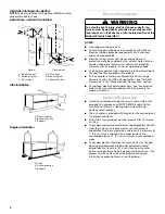
Installation Configurations ...........................................................3
Electrical Requirements ...............................................................4
Ductwork Requirements ..............................................................4

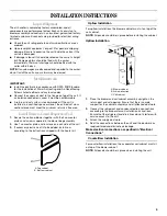
INSTALLATION INSTRUCTIONS ..................................................5

Inspect Shipment .........................................................................5
Install Ductwork............................................................................5

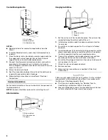
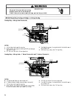
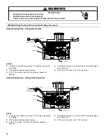
Install Blower—Cased Evaporator Coil........................................5
Install Filter....................................................................................6
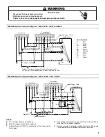
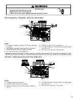
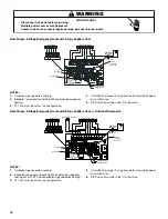
Make Electrical Connections .......................................................7
Complete Installation..................................................................20

SEQUENCE OF OPERATION ......................................................23

Cooling—Cooling Only or Heat Pump.......................................23
Heating—Electric Heat Only ......................................................23
Heating—Heat Pump .................................................................23

AIR HANDLER MAINTENANCE ..................................................23

ASSISTANCE OR SERVICE .........................................................23

Accessories ................................................................................23

Whirlpool

©

 Models WMAHM, WMAHV

WPIO-239E

Goodman 1

Hazards or unsafe practices could result in property
damage, product damage, severe personal injury or death. 

Hazards or unsafe practices may result in property
damage, product damage, personal injury or death. 

WARNING

CAUTION

Placeholder

for Bar

Code

Goodman 9

Hazards or unsafe practices may result in property
or product damage. 

CAUTION

Goodman 7

Installation and repair of this unit should
be performed ONLY by individuals meeting
the requirements of an “Entry Level Technician”
as specified by the Air-Conditioning, Heating and
Refrigeration Institute (AHRI). Attempting to
install or repair this unit without such background may 
result in product damage, personal injury or death.

WARNING

Goodman 6

HIGH VOLTAGE!

WARNING

Disconnect ALL power before servicing.

Multiple power sources may be present.

Failure to do so may cause property damage, 
personal injury or death.

Summary of Contents for WMAHM

Page 1: ...E OF OPERATION 23 Cooling Cooling Only or Heat Pump 23 Heating Electric Heat Only 23 Heating Heat Pump 23 AIR HANDLER MAINTENANCE 23 ASSISTANCE OR SERVICE 23 Accessories 23 Whirlpool Models WMAHM WMAHV WPIO 239E Goodman 1 Hazards or unsafe practices could result in property damage product damage severe personal injury or death Hazards or unsafe practices may result in property damage product damag...

Page 2: ...y hardware to connect the air handler and modular evaporator coil cabinets together are included with this air handler Goodman 33 WARNING This product is factory shipped for use with 208 240 1 60 electrical power supply DO NOT reconfigure this air handler to operate with any other power supply Goodman 34 WARNING To avoid property damage personal injury or death due to electrical shock this unit MU...

Page 3: ...story buildings Louvered closet doors shall be sized with the minimum opening required to provide minimum return air free area See Minimum Filter Requirements Chart Louvers installed in a closet to provide return air shall be sized with minimum opening required to provide minimum air return free area See Minimum Filter Requirements Chart Return air plenum installed through the floor shall be sized...

Page 4: ...90B Standard for the Installation of Warm Air Heating and Air Conditioning Systems latest edition The air handler is provided with flanges for the connection of the plenum and ducts All air filters not provided must be listed as Class 2 furnace air filters The supply and return ductwork must be adequately sized to meet the system s air requirements and static pressure capabilities Ductwork should ...

Page 5: ... cross sectional area must meet the minimum return air free area InstallBlower CasedEvaporatorCoil 1 Secure the coil and blower together with the 2 connector plates and screws supplied in the blower bag assembly 2 Use 1 connector plate and 6 screws on each side of the unit 3 If accessory electric heat is to be added install now according to the instructions shipped with the heater kit Upflow Insta...

Page 6: ...th of the unit 2 Install rubber isolation pads to reduce sound and vibration transmission 3 Ensure there is ample support for the unit and all attached ductwork 4 If installed above a finished ceiling or living space be sure to place a secondary drain pan under the entire unit and pipe the drain separately from the main condensate drain 5 Connect the refrigerant and condensate drain connections ac...

Page 7: ...63 5 260 1 677 15 x 20 38 1 x 50 8 260 1 677 2 Tons 900 to 1 000 CFM 480 3 097 20 x 30 50 8 x 76 2 288 1 858 14 x 25 35 6 x 63 5 288 1 858 3 Tons 1 100 to 1 300 CFM 576 3 716 14 x 25 35 6 x 63 5 346 2 232 16 x 25 40 6 x 63 5 346 2 232 3 Tons 1 300 to 1 500 CFM 672 4 335 16 x 25 40 6 x 63 5 404 2 606 20 x 25 50 8 x 63 5 404 2 606 4 Tons 1 500 to 1 700 CFM 768 4 955 20 x 25 50 8 x 63 5 461 2 974 20 ...

Page 8: ...property damage personal injury or death Room Thermostat W Y G R R G W Y R To Condensing Unit 24V Connections 18 Gauge 2 Wires Blue White Green Red Unit 18 Gauge 4 Wires With Cooling 3 Wires Without Cooling Contactor Coil To Comfort Alert Module If Used W2 W Y G R R G Y W Room Thermostat 18 Gauge 4 Wire With Cooling 3 Wire Without Cooling Outdoor Thermostat Optional Unit Red Green White Brown Blue...

Page 9: ...ing Multiple power sources may be present Failure to do so may cause property damage personal injury or death C W2 O Y R R BR G W R Y W Y O C W2 G R E Heat Pump Conventional Room Thermostat 18 Gauge 7 Wire WMAHM Unit Red Green White Blue BU 18 Gauge 5 Wire BU OR See Note 3 Outdoor Thermostat Optional Closed on Temperature Fall 18 Gauge 6 Wire Needed When Outdoor Thermostat Is Used BU W OR Y R Colo...

Page 10: ...stat closed enables high speed fan heating 3 OT1 PJ4 must be cut for this configuration 4 Cut HUM PJ6 jumper if using humidistat Humidistat opens on humidity rise 5 DIP Switch 4 must be in the ON position Goodman 6 Long HIGH VOLTAGE WARNING Disconnect ALL power before servicing Multiple power sources may be present Failure to do so may cause property damage personal injury or death See Note 3 See ...

Page 11: ...peed fan heating 4 Cut HUM PJ6 jumper if using humidistat Humidistat opens on humidity rise 5 DIP Switch 4 must be in the ON position Goodman 6 Long HIGH VOLTAGE WARNING Disconnect ALL power before servicing Multiple power sources may be present Failure to do so may cause property damage personal injury or death OT2 HUM N O P I D F F O YCON CONDENSER R E W1 OUTDOOR THERMOSTATS HEATPUMP W1 OT1 COM ...

Page 12: ...th OT2 closed enables high speed fan heating 3 OT2 PJ2 must be cut for this configuration 4 Cut HUM PJ6 jumper if using humidistat Humidistat opens on humidity rise 5 DIP Switch 4 must be in the ON position Goodman 6 Long HIGH VOLTAGE WARNING Disconnect ALL power before servicing Multiple power sources may be present Failure to do so may cause property damage personal injury or death 2nd Stage Hea...

Page 13: ...les high speed fan heating 3 OT1 PJ4 must be cut for this configuration 4 OT2 PJ2 must be cut for this configuration 5 Cut HUM PJ6 jumper if using humidistat Humidistat opens on humidity rise 6 DIP Switch 4 must be in the ON position Goodman 6 Long HIGH VOLTAGE WARNING Disconnect ALL power before servicing Multiple power sources may be present Failure to do so may cause property damage personal in...

Page 14: ...midistat Humidistat opens on humidity rise 5 DIP Switch 4 must be in the OFF position Goodman 6 Long HIGH VOLTAGE WARNING Disconnect ALL power before servicing Multiple power sources may be present Failure to do so may cause property damage personal injury or death Y1 W W2 E W1 O OTC CONDENSER YCON DI P OUTDOOR W1 HUM W2 HEATPUMP COM O W2 ED S WI HEATER W1 W2 24 VAC THERMOSTATS HUM G Y Y2 Y1 HUMID...

Page 15: ... enable low speed fan heating 4 Cut HUM PJ6 jumper if using humidistat Humidistat opens on humidity rise 5 DIP Switch 4 must be in the ON position Goodman 6 Long HIGH VOLTAGE WARNING Disconnect ALL power before servicing Multiple power sources may be present Failure to do so may cause property damage personal injury or death HUM N O P I D F F O YCON R OUTDOOR THERMOSTATS HEATPUMP W1 COM W2 W2 ED W...

Page 16: ...J4 must be cut for this configuration 4 Cut HUM PJ6 jumper if using humidistat Humidistat opens on humidity rise 5 DIP Switch 4 must be in the ON position Goodman 6 Long HIGH VOLTAGE WARNING Disconnect ALL power before servicing Multiple power sources may be present Failure to do so may cause property damage personal injury or death If Needed 2 nd Stage Heater Humidistat Optional Room Thermostat 1...

Page 17: ...J4 must be cut for this configuration 4 OT2 PJ2 must be cut for this configuration 5 Cut HUM PJ6 jumper if using humidistat Humidistat opens on humidity rise 6 DIP Switch 4 must be in the ON position Goodman 6 Long HIGH VOLTAGE WARNING Disconnect ALL power before servicing Multiple power sources may be present Failure to do so may cause property damage personal injury or death 1 J PN B13682704 HUM...

Page 18: ...fan heating 3 OT2 PJ2 must be cut for this configuration 4 Cut HUM PJ6 jumper if using humidistat Humidistat opens on humidity rise 5 DIP Switch 4 must be in the OFF position Goodman 6 Long HIGH VOLTAGE WARNING Disconnect ALL power before servicing Multiple power sources may be present Failure to do so may cause property damage personal injury or death 2 Speed Heat Pump 2 nd Stage Heater Humidista...

Page 19: ...ed fan heating W2 with OT2 closed enables high speed fan heating 3 OT1 PJ4 must be cut for this configuration 4 OT2 PJ2 must be cut for this configuration 5 Cut HUM PJ6 jumper if using humidistat Humidistat opens on humidity rise 6 DIP Switch 4 must be in the OFF position Goodman 6 Long HIGH VOLTAGE WARNING Disconnect ALL power before servicing Multiple power sources may be present Failure to do s...

Page 20: ...rflow through the indoor coil should be between 350 and 450 CFM per ton of cooling capacity or 350 to 450 CFM per 12 000 Btu h based on the rating of the outdoor condensing unit The WMAHV control board is factory set with DIP Switch 4 in the ON position and all other DIP switches are factory set in the OFF position For most applications the settings are to be changed according to the electric heat...

Page 21: ...ollowing table shows the DIP switch position for this feature NOTE The airflow will not make the decreasing adjustment in Electric Heat mode NOTE If no adjustment is required DIP switches 7 and 8 should be left in the OFF position Humidity Control When using a humidistat normally closed cut jumper PJ6 on the control board The humidistat will only affect the cooling airflow by adjusting the airflow...

Page 22: ...M WMAHM2000 SCFM High 0 1 1 240 1 500 1 800 2 160 0 2 1 170 1 460 1 740 2 080 0 3 1 120 1 360 1 680 1 990 0 4 1 060 1 280 1 610 1 890 0 5 980 1 200 1 520 1 790 0 6 900 1 110 1 430 1 690 Medium 0 1 900 1 380 1 540 1 730 0 2 850 1 320 1 490 1 670 0 3 790 1 270 1 450 1 590 0 4 740 1 200 1 400 1 520 0 5 680 1 140 1 350 1 420 0 6 605 1 040 1 280 1 320 Low 0 1 650 1 170 1 130 1 520 0 2 590 1 130 1 100 1...

Page 23: ...cer relay can be connected with the first sequencer to W1 on the thermostat or connected to a second heating stage W2 on the thermostat subbase AIR HANDLER MAINTENANCE IMPORTANT Do not operate system without a filter A filter is required to keep excessive dirt and dust from the coil blower and internal parts The filter is placed in the supply air return duct by the installer Inspect air filters at...

Page 24: ...WPIO 239E 2009 All rights reserved Registered Trademark TM Trademark of Whirlpool U S A Manufactured under license by Tradewinds Distributing Company LLC Jacksonville Florida 8 09 Printed in U S A ...

Reviews: