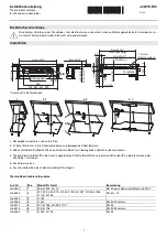
CUTOUT DIMENSIONS
Height
3
"
Min.
Width
Depth
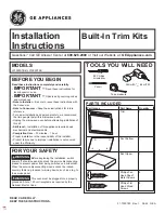
Trim Kit
Bottom Duct (1)
Side Duct (1)
1
”
Screws
(4 Req’d 2 Extra)
1/2
”
Screws
(11 Req’d 2 Extra)
Anti-Tip
Bracket (1)
Bottom
Bracket (1)
Upper Duct (1)
Template (1)
27
”
30
”
Height 16
3/4
”
Width 25
1/2
”
25
1/2
”
(min.),
28
1/2
”
(max.)
Depth
21
”
with flush mount receptacle.
(min.)
(22
3/4
”
if non-flush receptacle is
used)
PARTS LIST
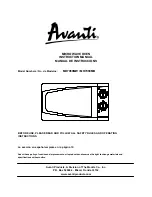
BUILT-IN TRIM KIT INSTALLATION INSTRUCTION
(KEEP FOR FURTHER REFERENCE)
FOR WHIRLPOOL TRIM-KIT MODELS: MK1197XH, MK1190XH
• FOR USE WITH WHIRLPOOL MICROWAVE OVEN MODELS : MT1195SG, GT1196SH,
GT1195SH, MT3185SH, 89990, 89999, 89998, (Y)KCMS185J, MT2210SJ
•
UL LISTED - FOR USE OVER ELECTRIC HEAT SOURCE
(INCLUDING MODELS - 27
”
: (Y)RBS275PD, (Y)GBS277PD, KEBI171D, (Y)KEBS177D
- 30
”
: (Y)RBS305PD, GBS307PD, (Y)KEBI101D, (Y)KEBS107D)
P/NO.: 3828W5U0085/8172239