Whirlpool Electric Down Draft Surface Unit, Installation Instructions Manual
The Whirlpool Electric Down Draft Surface Unit combines style and functionality, offering a powerful yet sleek addition to any kitchen. To ensure a hassle-free setup, we provide an easy-to-follow Installation Instructions Manual. Download this manual for free from our website and get started with your new appliance today!
Share
Download


Reviews:
No comments
Related manuals for Electric Down Draft Surface Unit

Omega
Brand: Omega Pages: 11
2000
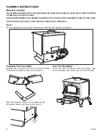
Brand: United States Stove Company Pages: 19

P2
Brand: KAWMET Pages: 44

P2
Brand: KAWMET Pages: 52

16-cube Series
Brand: Stuv Pages: 48

600 Series
Brand: RAIS Pages: 34
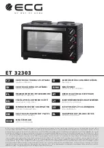
ET 32303
Brand: ECG Pages: 100

30 Series
Brand: NARVI Pages: 4
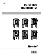
51
Brand: Handöl Pages: 16

1150
Brand: Cadac Pages: 8

Genesis
Brand: Jetboil Pages: 44
Beacon
Brand: Aarrow Pages: 28
ST4
Brand: Saltfire Pages: 6

302
Brand: Yakar Pages: 14

550
Brand: Valor Pages: 7

EL6300
Brand: Easylife Pages: 3

202
Brand: Yakar Pages: 28
VENUS
Brand: Cadel Pages: 352


