Whirlpool AGB 055/WP, Installation, Operating And Maintenance Instructions For The Installer And The User
The Whirlpool AGB 055/WP user manual provides all the necessary installation, operating, and maintenance instructions for both the installer and the user. This manual is available for free download from manualshive.com, ensuring easy access to essential product information for optimal use and performance.
Share
Download


Reviews:
No comments
Related manuals for AGB 055/WP
2200
Brand: Pastamaster Pages: 26
R220
Brand: Omcan Pages: 12
WPC100
Brand: Waring Pages: 44
31876500
Brand: GGMgastro Pages: 257
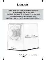
Master Pasta 90.730
Brand: Beper Pages: 56
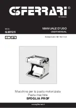
SFOGLIA PROF
Brand: G3 Ferrari Pages: 12
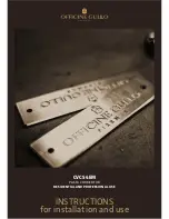
CVCS4EM
Brand: Officine Gullo Pages: 12
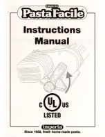
Imperia
Brand: PastaFacile Pages: 8
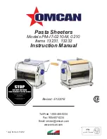
PM-IT-0210-M
Brand: Omcan Pages: 16
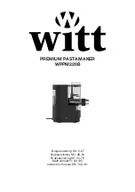
61650032
Brand: Witt Pages: 132
DOMINATOR PLUS E3204
Brand: Falcon Pages: 6

AX-GPC-1
Brand: Axis Pages: 16
63246
Brand: Hamilton Beach Professional Pages: 28
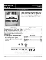
630-ROM4
Brand: Prince Castle Pages: 9
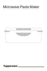
10049020724
Brand: Tupperware Pages: 47
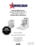
49117
Brand: Omcan Pages: 24
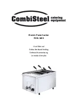
7455.1655
Brand: CombiSteel Pages: 18
Pates Creativ
Brand: Lagrange Pages: 66


