background image

5019 318 33271 

INSTALLATIONSANLEITUNG

Der Mindestabstand zwischen dem Kochfeld und der unteren Kante der Dunstabzugshaube muss bei 

Elektroplatten 50 cm und bei Gasherden oder kombinierten Herden 70 cm betragen. 

Schreiben die Installationsanweisungen des Gaskochfelds einen größeren Abstand vor, ist dieser 

natürlich zu beachten. 
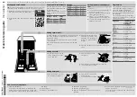
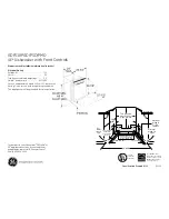
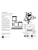
Beauftragen Sie einen qualifizierten Techniker mit der Installation. Folgen Sie bei der Installation der 

Nummerierung (1

Ö

2

Ö

3

Ö

.....). 

 WARNUNG:

 Schalten Sie das Stromnetz am Hauptschalter ab, bevor Sie den Anschluss der Abzugshaube 

vornehmen. 


WARNUNG: 

Prüfen Sie, ob das Abluftrohr und die Befestigungsmanschetten im Lieferumfang inbegriffen 

sind. Andernfalls sind sie separat zu beziehen. 

Hinweis: Die mit dem Symbol “(*)” bezeichneten Teile sind Zubehör, das nur mit bestimmten 

Modellen oder gar nicht geliefert wird und gesondert erworben werden muss.


WARNUNG: 

Aufgrund des schweren Gewichtes sind mindestens zwei oder noch mehr Personen zur 

Beförderung und Installation der Abzugshaube erforderlich.

INSTALLATION SHEET

The minimum distance between the support surface of the recipients on the cooking device and the 

lowest part of the hood must not be less than 50 cm in case of electric cookers and 70 cm for gas or 

combination cookers. 

If the installation instructions for a gas cooker specify a greater distance, then this distance must be 

observed. 
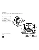
Contact a qualified technician for installation. To install, follow steps (1

Ö

2

Ö

3

Ö

.....). 

 WARNING:

 Disconnect the power at the house main switch before electrically connecting the hood. 


WARNING: 

Check if the exhaust pipe and fixing clamps are provided. Otherwise, they must be purchased 

separately. 

Note: Parts marked with the symbol “(*)” are optional accessories supplied only with some models 

or parts not supplied, to be purchased separately.


WARNING: 

Very heavy product; hood handling and installation must be carried out by at least two persons.

FICHE D’INSTALLATION

La distance minimum entre la surface de support des récipients sur le dispositif de cuisson et la partie 

la plus basse de la hotte ne doit pas être inférieure à 50 cm pour les cuisinières électriques et à 70 cm 

pour les cuisinières à gaz ou mixtes. 

Si les instructions d’installation du dispositif de cuisson à gaz indiquent une distance supérieure, il est 

nécessaire de la respecter. 
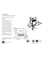
Faites appel à un technicien qualifié pour l’installation. Pour le montage, suivez la numérotation 

(1

Ö

2

Ö

3

Ö

.....). 

 AVERTISSEMENT :

 Coupez l’alimentation secteur avant de procéder au branchement électrique de la 

hotte. 


AVERTISSEMENT : 

Vérifiez si le conduit d’évacuation et les colliers de fixation sont fournis avec l’appareil. 

Dans le cas contraire, il conviendra de les acheter. 

Remarque : Les pièces portant le symbole “(*)” sont des accessoires en option fournis seulement avec 

certains modèles ou sont des pièces non fournies, à acheter à part.


AVERTISSEMENT : 

Appareil excessivement lourd ; la manutention et l’installation de la hotte doivent être 

effectuées par deux personnes ou plus.

D

GB

F

Summary of Contents for 806

Page 1: ...technician for installation To install follow steps 1Ö2Ö3Ö WARNING Disconnect the power at the house main switch before electrically connecting the hood WARNING Check if the exhaust pipe and fixing clamps are provided Otherwise they must be purchased separately Note Parts marked with the symbol are optional accessories supplied only with some models or parts not supplied to be purchased separately...

Page 2: ...rlo en cuenta Consulte a un técnico cualificado para la instalación Para el montaje siga la numeración 1Ö2Ö3Ö ADVERTENCIA Desconecte la red eléctrica doméstica antes de efectuar la conexión eléctrica de la campana ADVERTENCIA Compruebe que el tubo de descarga y las abrazaderas de fijación hayan sido suministradas adjuntas En caso contrario deberá comprarlos por separado Nota Las piezas marcadas co...

Page 3: ...ivo la movimentazione e installazione della cappa deve essere fatta da almeno due o più persone ΚΑΡΤΕΛΑ ΕΓΚΑΤΑΣΤΑΣΗΣ Η ελάχιστη απόσταση ανάμεσα στην επιφάνεια στήριξης των σκευών στη συσκευή μαγειρέματος και στο χαμηλότερο σημείο του απορροφητήρα δεν πρέπει να είναι μικρότερη από 50 cm σε περίπτωση ηλεκτρικών εστιών και από 70 cm σε κουζίνες αερίου ή μικτές Εάν οι οδηγίες εγκατάστασης της εστίας ...

Page 4: ...5019 318 33271 ...

Page 5: ...5019 318 33271 ...

Page 6: ...5019 318 33271 ...

Page 7: ...5019 318 33271 ...

Page 8: ...5019 318 33271 ...

Page 9: ...ctions and or pipes 10 The ventilation ducts must always discharge to the outside 11 The Manufacturer declines any liability for improper use or incorrect setting of the controls 12 The appliance is not intended for use by children or persons with limited physical sensory or mental abilities or without experience and knowledge of it unless they are under the supervision of or instructed in its use...

Page 10: ...od has not been damaged during transport Declaration of conformity This product has been designed manufactured and put on the market in conformity with safety objectives of the Low Voltage Directive 2006 95 EC which replaces 73 23 EEC as amended protection requirements of EMC Directive 89 336 EEC amended by Directive 93 68 EEC Troubleshooting guide If the hood does not work Is the plug properly in...

Page 11: ... A Support bracket with cables and hooking brackets B Hood fitted motor lights assembly C Cover D Grease filter E Carbon filter F Carbon filter fixing elements G Control rod H Bottom halogen lamps I Halogen lamps top I F NL E P GB D GR ...

Page 12: ...led with motor and lamps installed Support bracket Cover Assembly template Filter s Instruction manual 1 adapter Torx T10 1 adapter Torx T20 3 plugs 10 x 60 mm 3 screws 6 x 70 mm 5 screws 3 5 x 6 5 mm 6 screws 2 9 x 9 5 mm Installation dimensions Cooktop surface 70 cm gas or combi cookers 50 cm electric cookers I F NL E P GB D GR ...

Page 13: ...um distance from burners indicated on the first page of the manual Fig 4 After preparing the electrical connection fit the support bracket to the ceiling running the cables for electrical connection through the middle hole Fix with 3 screws Important Detail A support bracket is equipped with a wire yellow green which must be connected to the earth of the house electrical system Fig 5 Fix the hood ...

Page 14: ...cording to the speed sequence therefore every time the extraction power selection button is pressed the extraction speed power increases by one level and switches off Stand by if the button is touched again when the hood is on extraction speed power 4 Note Extraction speed power 4 remains on for 5 minutes after which the extraction motor switches to speed 2 The hood can also be switched off Stand ...

Page 15: ...ion signalling GREEN LED FLASHING on control panel Firstly carry out filter maintenance as described in the relevant section Press prolonged for more than 3 seconds the extraction power selection button the LED stops flashing to indicate that signalling has been reset and the hood switches off Reset carbon filter saturation signalling ORANGE amber LED FLASHING Firstly carry out filter maintenance ...

Page 16: ...d life and should be washed once a month by hand or in a dishwasher at a low temperature and with short cycle Cleaning in a dishwasher may cause discolouring of the grease filter but its filtering efficiency is unaffected Grease filter maintenance 1 Disconnect the hood from the power supply 2 Remove the grease filter Fig 3 by pulling the spring release handle 3 Remove the carbon filter fitted on t...

Reviews: