SERVICE MANUAL
FILE NO. 33
0
-200
5
15GR
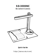
DOCUMENT CAMERA
T
LP-C001
The above models are classified as green product (s) (*1), as indicated by the underlined serial number (s).
This Service Manual describes replacement parts for green product (s). When repairing any green product (s), use
the parts described in this manual and lead-free solder (*2).
For (*1) and (*2) , see the next page.
Published in Japan,
December
2005 GREEN
© TOSHIBA
CORPORATION
Summary of Contents for TLP-C001 - Document Camera
Page 11: ...5 1 Remove two S 2 force 2 8 3lb 2 Take off the joint cover CAMERA HEAD COVER KIT 23587753 10 ...
Page 22: ...4 CIRCUIT DIAGRAM 4 1 U001 MAIN PCB 4 2 E002 CAMERA HEAD ASSY 21 ...
Page 23: ...4 3 P0D1_ISP module 22 ...
Page 28: ...Y012 POWER CORD UK 23587773 Y013 RGB CABLE 23587774 Y014 LED HOOD 23587775 27 ...
Page 31: ...U001 MAIN PCB 23587759 U002 KEY PAD PCB 23587760 U003 IR RECEIVER 23587761 30 ...
Page 32: ...2 3 Label A004 1 LABEL SPEC A004 2 LABEL SPEC 31 ...
Page 33: ...T O S H I B A C O R P O R A T I O N 1 1 SHIBAURA 1 CHOME MINATO KU TOKYO 105 8001 JAPAN ...