‒
1
‒
(English)
Observe the safety precautions described in the Operation Manual of the Occupancy
sensor, Installation Manual and Operation Manual of the 4-way cassette type air
conditioner (indoor unit), or the installation manual supplied with the ceiling panel.
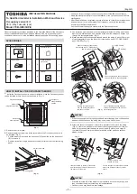
ACCESSORIES
Part Name
Q’ty
No.
1
1
2
1
3
1
Occupancy sensor
CORD CLAMP
SCREW
Part Name
Q’ty
No.
4
1
5
1
6
1
Operation Manual
Installation Manual
(this manual)
CD-ROM
HOW TO INSTALL THE OCCUPANCY SENSOR
ೈ
Install the Occupancy sensor in correct orientation, since the Occupancy sensor
can be installed at only one corner as shown in (Fig. 1).
(Fig. 1)
Electrical control box
Occupancy
sensor installing
position
Indoor unit
refrigerant pipe side
Indoor unit
drain pipe side
1.
Remove the air inlet grille.
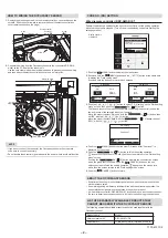
2.
Remove the adjust corner cap at the corner where the Occupancy sensor is to
be installed. (Fig. 2)
• Pull the adjust corner cap in the direction of
(1)
and slide it in the direction of
(2)
to remove it.
• Remove strap from the pin and detach the adjust corner cap from the ceiling
panel.
(1)
(2)
Ceiling panel
Adjust corner cap
(Fig. 2)
3.
The insulation pad is packed in the two rectangular holes for ceiling panel wires.
Remove the insulation pad, and pass the wires from the occupancy sensor unit
through the rectangular holes. (Fig. 3)
4.
Make sure that the black sponge wrapped around the wiring is about 20 mm out
of the rectangular hole on the indoor unit side, and
fi
x it with
2
CORD CLAMP
by
3
SCREW. (Fig. 3)
20 mm
SCREW
CORD CLAMP
Pass the occupancy sensor lead wire
through the hole in the ceiling panel
Pull out the black sponge wrapped
around the wiring about 20 mm from
the rectangular hole.
Remove the insulation pad
from the rectangular hole on
the indoor unit side.
Pass the occupancy sensor lead
wire through the
2
CORD CLAMP
and
fi
x it with
3
SCREW
(Fig. 3)
3
2
CAUTION
• If the black sponge is not properly positioned, water leakage, dew condensation,
and dew condensation on the wiring may occur, so be sure to do so.
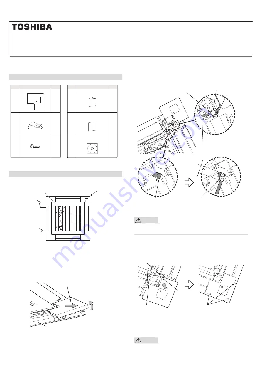
5.
Attach the sensor to the panel. At this time, be careful not to pinch the wiring.
(Fig. 4) If there is a part where the claws of the occupancy sensor unit are not
fi
tted, it may cause water leakage, so push claws A (2 places) and claws B
(3 places)
fi
rmly and
fi
rmly to make sure that the sensor part does not
fl
oat.
please con
fi
rm.
There are claws B here,
so push it in
fi
rmly.
Push in the claw B (3 places) on the back
side of the Occupancy sensor so that
they
fi
t.
Insert the claw A (2 places) of the sensor
part into the square holes of the panel in
the direction of the arrow.
Claw A
Claw A
Claw A
(Fig. 4)
CAUTION
• Press the two claws B of the adjust corner cap
fi
rmly as far as they will go, and
then check that the adjust corner cap is closely attached.
• Failure to do so may result in water leakage.
INSTALLATION MANUAL
• Thank you for purchasing Occupancy sensor kit for TOSHIBA air conditioners.
• Read this manual carefully for correct installation of the Occupancy sensor before
starting work.
• After the installation is completed, execute a test run to check for normal operation
and explain how to use and maintain the Occupancy sensor to the customer
according to the Operation Manual.
Ask the customer to keep this manual with the Operation Manual.
To Quali
fi
ed Installer in Installation Work and Service
Occupancy sensor kit
(for 4-Way cassette type)
Model: TCB-SIR33UP-E