background image

TA8266HQ 

2006-04-28 

1


TOSHIBA Bipolar Linear Integrated Circuit    Silicon Monolithic 

TA8266HQ 


Max Power 35 W BTL 

×

 4 ch Audio Power IC 


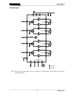
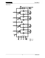
The TA8266HQ is 4 ch BTL audio power amplifier for car audio 

application. 

This IC can generate more high power: P

OUT

MAX = 35 W as it 

is included the pure complementary PNP and NPN transistor 
output stage. 

It is designed low distortion ratio for 4 ch BTL audio power 

amplifier, built-in stand-by function, muting function, and 
diagnosis circuit which can detect output to V

CC

/GND short and 

over voltage input mode. 

Additionally, the AUX amplifier and various kind of protector 

for car audio use is built-in. 
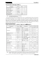
 

Features 


High power : P

OUT

MAX (1) = 35 W (typ.) 


(V

CC

 = 14.4 V, f = 1 kHz, JEITA max, R

L

 = 4 


P

OUT

MAX (2) = 31 W (typ.) 


(V

CC

 = 13.7 V, f = 1 kHz, JEITA max, R

L

 = 4 


P

OUT

 (1) = 23 W (typ.) 


(V

CC

 = 14.4 V, f = 1 kHz, THD = 10%, R

L

 = 4 


P

OUT

 (2) = 20 W (typ.) 


(V

CC

 = 13.2 V, f = 1 kHz, THD = 10%, R

L

 = 4 


Built-in diagnosis circuit (pin 25) 


Low distortion ratio: THD = 0.02% (typ.) 


(V

CC

 = 13.2 V, f = 1 kHz, P

OUT

 = 5 W, R

L

 = 4 


Low noise: V

NO

 = 0.18 mVrms (typ.) 


(V

CC

 = 13.2 V, R

g

 = 0 

, G

V

 = 34dB, BW = 20 Hz~20 kHz) 


Built-in stand-by switch function (pin 4) 


Built-in muting function (pin 22) 


Built-in AUX amplifier from single input to 2 channels output (pin 16) 


Built-in various protection circuit 


:  Thermal shut down, over voltage, out to GND, out to V

CC

, out to out short, speaker burned 


Operating supply voltage: V

CC (opr)

 = 9~18 V 


Note 1: Install the product correctly. Otherwise, it may result in break down, damage and/or degradation to the 

product or equipment. 

Note 2:  These protection functions are intended to avoid some output short circuits or other abnormal conditions 

temporarily. These protect functions do not warrant to prevent the IC from being damaged. 


- In case of the product would be operated with exceeded guaranteed operating ranges, these 
protection features may not operate and some output short circuits may result in the IC being 
damaged. 


Weight: 7.7 g (typ.) 

Summary of Contents for TA8266HQ

Page 1: ...f 1 kHz THD 10 RL 4 Ω Built in diagnosis circuit pin 25 Low distortion ratio THD 0 02 typ VCC 13 2 V f 1 kHz POUT 5 W RL 4 Ω Low noise VNO 0 18 mVrms typ VCC 13 2 V Rg 0 Ω GV 34dB BW 20 Hz 20 kHz Built in stand by switch function pin 4 Built in muting function pin 22 Built in AUX amplifier from single input to 2 channels output pin 16 Built in various protection circuit Thermal shut down over volt...

Page 2: ...be omitted or simplified for explanatory purpose RL RL RL 11 9 8 7 5 2 3 17 18 19 21 24 23 12 15 14 1 20 6 RL IN1 IN2 IN3 AUX IN IN4 13 16 C1 C1 C1 C1 PRE GND 10 25 4 22 OUT1 PW GND1 OUT1 OUT2 PW GND2 OUT2 OUT3 PW GND3 OUT3 OUT4 PW GND4 OUT4 TAB VCC1 VCC2 C 3 R 1 C 4 C 2 PRE GND PW GND STBY DIAGNOSIS OUT RIP MUTE C 5 C6 ...

Page 3: ...y means of controlling pin 4 stand by terminal to high and low the power supply can be set to ON and OFF The threshold voltage of pin 4 is set at about 3VBE typ and the power supply current is about 2 µA typ at the stand by state Control Voltage of pin 4 VSB Stand by Power VSB V ON OFF 0 1 5 OFF ON 3 VCC Adjustage of Stand by SW 1 Since VCC can directly be controlled to ON or OFF by the microcompu...

Page 4: ...ler of which operating voltage is less than 5 V Terminal 22 may not be pulled up and shall be controlled by OPEN LOW When it is obliged to do it must be pulled up via diode because it has to defend flowing reverse current to internal circuit of pin 22 VCC Small current capacity switch BATTERY Stand By VCC DIRECTLY FROM MICROCOMPUTER BATTERY Stand By Stand by Switch Method Figure 3 Conventional Met...

Page 5: ...s possible to protect all the system of apparatus as well as power IC protection In case of being unused this function use this IC as open connection on pin 25 5 1 In Case of Shorting Output to VCC GND or Over Voltage Power Supplied NPN transistor Q1 is turned on Threshold of over voltage protection VCC 22 V typ 5 2 In Case of Shorting Output to Output NPN transistor Q1 is turned on and off in res...

Page 6: ...ism The guess mechanism of a burning accident of the speaker Abnormal output offset voltage voltage between OUT and OUT over 4 V is made by the external circuit failure Note 4 The speaker impedance becomes 1 Ω or less as it is in a rare short circuit condition The current more than 4 A flows into the speaker and the speaker is burned Note 4 It is appeared by biased input DC voltage for example lar...

Page 7: ... possible to judge how the power IC condition is if a micro controller detects the 25pin voltage that is smoothed out with LPF It is recommend that the threshold voltage Vth is set up as higher as possible because output level of LPF is changed according to an input signal for example Vth is set up to 4 V if 25pin is pulled up to 5 V line Output voltage of L P F Output power 5 V Figure 10 Operatin...

Page 8: ... precautions and conditions set forth in this documents Electrical Characteristics unless otherwise specified VCC 13 2 V f 1 kHz RL 4 Ω Ta 25 C Characteristics Symbol Test Circuit Test Condition Min Typ Max Unit Quiescent current ICCQ VIN 0 200 400 mA POUT MAX 1 VCC 14 4 V max Power 35 POUT MAX 2 VCC 13 7 V max Power 31 POUT 1 VCC 14 4 V THD 10 23 Output power POUT 2 THD 10 17 20 W Total harmonic ...

Page 9: ...0 6 RL IN1 IN2 IN3 IN4 13 C1 C1 C1 C1 PRE GND 10 25 4 22 OUT1 PW GND1 OUT1 OUT2 PW GND2 OUT2 OUT3 PW GND3 OUT3 OUT4 PW GND4 OUT4 TAB VCC1 VCC2 C 3 R 1 C 4 1 µF C 2 PRE GND PW GND STBY DIAGNOSIS OUT RIP MUTE 3900 µF 0 22 µF 0 22 µF 0 22 µF 10 µF 10 kΩ C 5 0 1 µF 0 22 µF AUX IN 16 0 22 µF C6 ...

Page 10: ...r POUT W T H D POUT Total harmonic distortion T H D 10 0 30 0 400 20 100 200 300 RL VIN 0 0 1 100 0 01 1 0 1 1 10 10 100 10 kHz 1 kHz 100 Hz VCC 13 2 V RL 4 Ω 0 1 100 0 01 1 0 1 1 10 10 100 13 2 V 16 0 V 9 0 V f 1 kHz RL 4 Ω Frequency f Hz T H D f Total harmonic distortion T H D 100 10 100 k 0 001 1 1 k 0 01 0 1 10 k OUT2 3 VCC 13 2 V RL 4 Ω Pout 5 W OUT3 OUT4 ...

Page 11: ...0 1 k 60 30 10 k 40 20 50 10 VCC 13 2 V RL 4 Ω Rg 620 Ω Vrip 0dBm 100 10 100 k 70 0 1 k 60 30 10 k 40 20 50 10 VCC 13 2 V RL 4 Ω VOUT 0dBm Rg 620 Ω OUT1 OUT2 3 4 100 10 100 k 70 0 1 k 60 30 10 k 40 20 50 10 OUT2 OUT1 3 4 VCC 13 2 V RL 4 Ω VOUT 0dBm Rg 620 Ω 100 10 100 k 70 0 1 k 60 30 10 k 40 20 50 10 OUT3 OUT4 OUT3 OUT1 2 VCC 13 2 V RL 4 Ω VOUT 0dBm Rg 620 Ω 100 10 100 k 1 k 10 k 70 0 60 30 40 20...

Page 12: ... Ta C PD MAX Ta Allowable power dissipation P D MAX W 25 0 150 0 120 75 60 100 40 20 80 100 50 125 INFINITE HEAT SINK RθJC 1 C W HEAT SINK RθHS 3 5 C W RθJC RθHS 4 5 C W NO HEAT SINK RθJA 39 C W 100 10 100 k 0 40 1 k 5 20 10 k 15 25 10 30 35 VCC 13 2 V RL 4 Ω VOUT 0dBm 0 10 40 30 50 20 60 70 5 15 20 10 25 0 9 V 13 2 V 16 V f 1 kHz RL 4 Ω ...

Page 13: ...TA8266HQ 2006 04 28 13 Package Dimensions Weight 7 7 g typ ...

Page 14: ...TA8266HQ 2006 04 28 14 ...

Page 15: ...oltage to a speaker directly Over current Protection Circuit Over current protection circuits referred to as current limiter circuits do not necessarily protect ICs under all circumstances If the Over current protection circuits operate against the over current clear the over current status immediately Depending on the method of use and usage conditions such as exceeding absolute maximum ratings c...

Page 16: ...energy control instruments airplane or spaceship instruments transportation instruments traffic signal instruments combustion control instruments medical instruments all types of safety devices etc Unintended Usage of TOSHIBA products listed in this document shall be made at the customer s own risk 021023_B The products described in this document shall not be used or embedded to any downstream pro...

Reviews: