background image

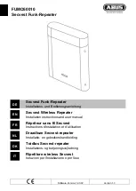
TOSHIBA

Telecommunication Systems Division

DKT2404-UDR200

Repeater

Operation Guide

Title Page

December 2010

Summary of Contents for Strata CIX DKT2404-UDR200

Page 1: ...TOSHIBA Telecommunication Systems Division DKT2404 UDR200 Repeater Operation Guide Title Page December 2010 ...

Page 2: ...e refer to the Toshiba FYI web site Toshiba America Information Systems shall not be liable for any commercial losses loss of revenues or profits loss of goodwill inconvenience or exemplary special incidental indirect or consequential damages whatsoever or claims of third parties regardless of the form of any claim that may result from the use of this document THE SPECIFICATIONS AND INFORMATION PR...

Page 3: ......

Page 4: ... the malfunc tion by TAIS or its authorized dealer with new or refurbished parts at their option If TAIS or one of its autho rized dealers does not replace or repair such parts the retail customer s sole remedy will be a refund of the price charged by TAIS to its dealers for such parts as are proven to be defective and which are returned to TAIS through one of its authorized dealers within the war...

Page 5: ...REGISTRATION 6 Registering Multiple Repeaters 7 MAP BASE STATION COVERAGE 7 INSTALLING THE REPEATER 8 Correct Location 8 Test The Location 9 Installation 9 MAINTENANCE 10 SAFETY INFORMATION 10 TROUBLE SHOOTING 11 IMPORTANT ELECTRICAL CONSIDERATIONS 11 FCC REGULATORY INFORMATION 12 Part 15 Compliance 12 Privacy Information 12 Radio Interference Information 12 I C NOTICE 13 Terminal Equipment 13 Rad...

Page 6: ...This page is intentionally left blank ...

Page 7: ...ports up to 6 repeaters to a base station in star configuration and up to 3 repeaters in a daisy chain configuration Eliminates the need for complex and time consuming programming when adding two or more repeaters in a daisy chain configuration Simply register the UDR200 to a base station and it will self configure itself as the second or third repeater when installed in a daisy chain The DKT2404 ...

Page 8: ...ance from your handset try the following Place the repeaters at least three feet from metal structures and six feet from computers fax machines or other electronic equipment Place the repeater unit as high as possible in the room Use an AC outlet not associated with computer or electromagnetic equipment Refer to MULTIPLE REPEATER CONFIGURATION on page 4 MAP BASE STATION COVERAGE on page 7 and INST...

Page 9: ...set operates in the same manner as when connected to the base Refer to Figure 2 The handoff from the base to the repeater can be completely invisible to the end user even during an active call Each base station can support up to six repeaters refer to Figure 3 The repeater must be at least 35 feet 10 meters from the base station Use the mapping procedure MAP BASE STATION COVERAGE on Page 7 to dete...

Page 10: ...TION Up to six repeaters can be registered to a base station Base station and repeaters operate in all directions Coverage is spherical extending in all directions including up and down Repeaters must be at least 35 feet 10 m apart and the same minimum distance from the base station Figure 3 Overhead view of Multiple Repeater Coverage ...

Page 11: ... 10 TOSHIBA 5 of 16 Repeaters can be daisy chained to increase the coverage area in one direction Figure 4 Daisy chain Repeater Configuration The coverage area of the base stations and repeaters is spherical it extends through walls floors and ceilings Figure 5 Correct Repeater Placement ...

Page 12: ...ation key on the back of the repeater This will start the registration process The LINK LED on the front of the repeater will flash once per second On 500 ms Off 500 ms in registration mode 3 Press and hold the Base Left key CT Phone select Key on the base station This will start the registration The POWER LED on the Base will start to flash almost twice each second On 300 ms Off 300 ms in registr...

Page 13: ...ion steps above 3 Disconnect the power supply from the repeater 4 Perform 1 3 for each repeater for this base station 5 Physically install the repeaters As the power supply is connected to each repeater the Link LED should remain lit UDR100 and UDR200 repeaters can be combined in a star configuration Refer to Figure 3 on Page 4 Figure 7 Both Types in Star Configuration Do not mix UDR100 and UDR200...

Page 14: ...NG THE REPEATER Register the repeaters before installing them Repeaters can be installed Wide area array where are base stations are within the range of the base station Daisy chain sequential array Mix of both Ensure that each repeater is at least 35 feet 10 m away from the base station or other repeaters Refer to Figure 2 on Page 3 Correct Location Place the repeater as high as possible It shoul...

Page 15: ...hould remain on and steady indicating that the repeater has a good signal from the base If the LED flashes the repeater is not getting a good signal The repeater may be too far away from the base there may be interference from electronic devices or the signal might be blocked by thick walls or metal objects Try moving the repeater to another location Installation 1 Hold the repeater in its final l...

Page 16: ...oduct should never be placed near or over a radiator or heat register This product should not be placed in a built in installation unless the proper ventilation is provided This product should be operated only from the type of power source indicated on the marking label Do not allow anything to rest on the power cord Do not locate this product where the cord will be damaged by people walking on it...

Page 17: ...ng can pass through your household wiring and damage any device connected to it This repeater is no exception Changes or modifications to this product not expressly approved by Toshiba America Information Systems Inc or operation of this product in any way other than as detailed by this manual could void your authority to operate this product Table 2 Trouble Shooting for Users Problem Solution The...

Page 18: ...FECTIVE If these noises continue and are too distracting check around your office to see what appliances may be causing the problem In addition we recommend that the base not be plugged into a circuit that also powers a major appliance because of the potential of interference For best performance ensure that the antenna on the base unit is fully extended In the unlikely event that you consistently...

Page 19: ...med based on a Declaration of Conformity indicating that Industry Canada technical specifications were met It does not imply that Industry Canada approved the equipment Radio Equipment The term IC before the radio certification number only signifies that Industry Canada technical specifications were met Operation is subject to the following two conditions 1 this device may not cause interference a...

Page 20: ...DKT2404 UDR200 DECT Repeater I C NOTICE 14 of 16 TOSHIBA DKT2404 UDR200 Repeater 12 10 ...

Page 21: ...DKT2404 UDR200 DECT Repeater I C NOTICE DKT2404 UDR200 Repeater 12 10 TOSHIBA 15 of 16 ...

Page 22: ...THIS IS THE END OF THE DOCUMENT ...

Reviews: