INSTALLATION MANUAL
To Personnel Charged in Installation Work and Service
Wireless remote controller kit
Model: RBC-AX32U(W)-E, RBC-AX32U(WS)-E
EB01600301 (EN)
• Thank you for purchasing Wireless remote controller kit for TOSHIBA air conditioners.
• Read this manual carefully for correct installation of the wireless remote controller kit
before starting work.
• After the installation is completed, execute a test run to check for normal operation
and explain how to use and maintain the wireless remote controller kit to the customer
according to the Owner’s Manual.
Ask the customer to keep this manual with the Owner’s Manual.
Observe the safety precautions described in the Owner’s Manual of the wireless
remote controller kit, Installation Manual and Owner’s Manual of the 4-way cassette
type air conditioner (indoor unit), or the installation manual supplied with the ceiling
panel.
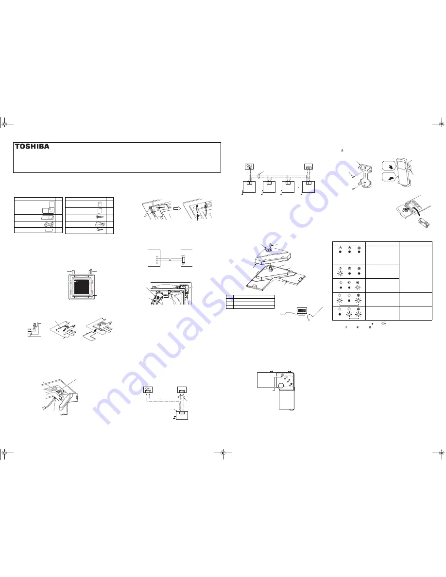
Accessories
Settings for the signal receiving unit before installation
Before installing the signal receiving unit, make the following settings referring to each
description.
• To install the wireless remote controller together with wired remote controller
,
configure the “Multiple remote controller installation”
• When ceiling height exceeds the standard height (factory default), refer to the
"Installing indoor unit on high ceiling" on installation manual of the indoor unit.
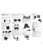
How to install the signal receiving unit
Install the signal receiving unit
in correct orientation, since
the signal receiving unit can
be installed at only one corner
as shown in (Fig. 1).
1.
Remove the air intake grille.
2.
Remove the adjust corner
cap at the corner where the
signal receiving unit is to be
installed. (Fig. 2)
Pull the knob of the adjust corner cap in the arrow
1
direction. Remove the adjust
corner cap.
* The knob is provided only on one side of the cap. Be sure to detach the cap from the
knob side.
3.
A pad is packed in the two rectangular holes (indoor unit side and signal receiving
unit side) for ceiling panel wires. Remove the pads temporarily, and pass the wires
from the wireless signal receiving unit through the rectangular holes. (Fig. 3)
4.
After the wiring is completed following “How to wire the signal receiving unit” below
without slack of the wires, pull the black pad that covers the wire by approx. 20 mm
out of the rectangular hole on the indoor unit side, and then clamp the wires with the
supplied clamp tightened with the screw. Then return the packing removed from the
rectangular hole on the signal receiving unit to the original position. (Fig. 3)
* Securely position the black pad and fix the packing. Failure to do so may cause water
leakage or dew drop on the unit and wires.
Part Name
Q’ty
Signal receiving unit
1
Remote controller
1
Remote controller holder
1
Battery
2
Owner’s Manual
1
Installation Manual (this
manual)
1
Tapping screw
M4 × 16 mm
2
Clamp
1
Clamp screw
M4 × 12 mm
1
Part Name
Q’ty
Indoor unit
drain pipe side
Indoor unit
refrigerant pipe
side
Indoor unit
electrical
control box
Signal receiving
unit installing
position
(Fig. 1)
1
Adjust corner cap
Knob
Ceiling panel
Adjust corner cap
(Fig. 2)
Clamp
Remove the pad from the
rectangular hole on the signal
receiving unit side, clamp the
wires with the clamp, secure the
clamp with the M4 x 12 mm
screw, and then return the pad to
the original position.
Pull the black pad that covers the wire
by approx. 20 mm out of the hole.
Remove the pad from the
rectangular hole on the indoor
unit side.
(Fig. 3)
5.
Attach the signal receiving unit to the ceiling panel, while taking care not to catch the
wires. (Fig. 4)
• Push the three claws of the adjust corner cap firmly as far as they will go. Failure to
do so may result in water leakage.
Note:
Do not bundle these control signal wires with the power wire to avoid
malfunction.
How to wire the signal receiving unit
<Connection diagram>
<Connection>
Connect the wires from the signal receiving unit to the remote controller connection
terminal block of the indoor unit. (The terminals are nonpolar.)
• Clamp the redundant portion of the wires with the clamps in the electrical control box.
Multiple remote controller installation
The control by two remote controllers is enabled by installing the wireless remote
controller with the wired remote controller for an indoor unit.
(Max. 2 remote controllers of wireless or wired are insatiable.)
“2-remote controllers” controlling means that one or multiple units are operated by the
multiple remote controllers.
Note:
1.
Upon confirmation of the terminal numbers of the indoor unit, connect the control
wire without miswiring. (If applied 220 - 240 V, damage the unit.)
2.
The multiple wireless remote controller kits cannot concurrently be used for an
indoor unit.
3.
When installing simultaneously the wireless remote controller with the wired remote
controller, set one of them as the follower remote controller.
• To use wired remote controller or Lite-vision plus remote controller as a follower,
settings must be changed. For the details, refer to the installation manual of each
controller.
• To use the wireless remote controller as a follower, set bit 4 (Follower side) of DIP
switch SW30 on the signal receiving unit P.C. board to ON.
2-remote controllers
The indoor unit is operated if either wireless or wired remote controller is set as header
or follower remote controller.
(Total wire length: Within 400 m)
Rectangular holes
Claws
Insert the two claws on the adjust corner
cap (with signal receiving unit) into the
rectangular holes of the ceiling panel in
the arrow direction.
Push the adjust corner cap in the arrow
directions so that the three claws are
fitted.
(Fig. 4)
Indoor unit
Signal receiving unit
White
Black
white
Remote controller
connection
terminal block
Electrical control box
Indoor unit remote
controller connection
terminal block
Clamps
Clamping claw
Signal receiving unit
A B
Wireless remote
controller kit (Header)
Wired remote
controller (Follower)
(Sold separately)
Control wire
(Locally procured)
2 x 0.5 to 2.0 mm
2
Indoor unit
Earth
Remote controller
connection terminal
block
Signal receiving unit
Group control
Header and follower remote controllers are operable even if they are installed to any
indoor unit.
(Total wire length: Within 200 m)
Remote controller address (A-B selection) setting
• When two or more signal receiving units are installed in a room, a unique address
can be set for each signal receiving unit to prevent interference.
• Address (A-B selection) must be changed on both signal receiving unit and wireless
remote controller.
• For the details of address change (A-B selection) on wireless remote controller, refer
to the owner's manual.
Turn off the indoor unit power supply. Turn on the bit 4 of DIP switch SW30 on the
signal receiving unit P.C. board.
The setting change is shown below.
DIP switch [SW30]
Test run (Forced cooling operation)
Requirement:
• Finish the forced cooling operation in a short time because it applies excessive
strength to the air conditioner.
How to perform forced cooling operation
1.
When TEMPORARY button is pushed for 10 seconds or more, “Pi!” sound is heard
and the operation changes to a forced cooling operation. After approx. 3 minutes, a
cooling operation starts forcedly.
Check cool air starts blowing. If the operation does not start, check wiring again.
2.
To stop a test operation, push TEMPORARY button once again (Approx. 1 second).
• Check wiring / piping of the indoor and outdoor units in forced cooling operation.
4
ON=follower OFF=header
3
ON=B
OFF=A
2
Not used
1
Not used
A B
A B
A B
A B
Wireless remote
controller kit (Header)
Wired remote
controller (Follower)
(Sold
separately)
Control wire for group control
(Locally procured)
2 x 0.5 to 2.0 mm
2
Earth
Remote
controller
connection
terminal block
Signal receiving
unit
Earth
Earth
Earth
Indoor unit
No.1
Indoor unit
No.2
Indoor unit
No.3
Indoor unit
No.4
Clamper
Screw
DIP switch SW30
Signal receiving unit P.C. board
Adjust corner cap with signal receiving unit
Signal receiving unit cover
SW30
1
ON
2
子Follower/親Header
Address
B/A
3
4
3
4
TEMPORARY
button
How to handle the remote controller
•
To set the remote controller on the wall
Push
button at the installation position on the wall to check that the signal from the
remote controller is received correctly.
• Loading Batteries
1.
Remove the battery cover.
2.
Insert 2 new batteries (R03 [AAA]) following the (+)
and (-) positions.
Self-diagnosis function and measures
• The following table shows a few examples. For details of indoor unit errors, refer to
the Installation Manual of the indoor unit.
LEDs on the signal receiving unit
: OFF
: Blinking (at intervals of 0.5 seconds)
LED color
: Green
: Green
: Orange
Notes on installing remote controller
• When using a wireless remote controller in the remote controller holder on a wall,
turn on a fluorescent light and operate the remote controller at the installation
position. Make sure that the air conditioner operates normally and then secure the
remote controller holder on the wall.
• When installing a remote controller that senses room temperature with the sensor,
avoid the following places.
• A place exposed to direct cool air, warm air or direct sunlight
• A place subject to thermal effects
Explanation to the customer
• After the installation work has been completed, execute a test run to check for normal
operation and then hand the customer the Owner’s Manual and Installation Manual of
the wireless remote controller kit.
• Explain how to use and maintain the wireless remote controller kit to the customer
according to the Owner’s Manual of the wireless remote controller kit.
LED
Possible cause
Measures
These LEDs do not light or blink
even if the remote controller is
operated.
- Power is not turned on.
- Incorrect connection between
signal receiving unit and
indoor unit
Check connections and
reconnect wires correctly, if
necessary.
Loose connection between
signal receiving unit and indoor
unit
Incorrect or loose connection
between indoor unit and
outdoor unit
The protective device of the
outdoor unit is activated.
Check the outdoor unit.
The protective device of the
indoor unit is activated.
Check the indoor unit.
1
2
Screw
Tapping screw
M4 × 16 mm
Remote controller holder
Remote
controller
Remote
controller holder
Push
Put on.
A
C
L
+01ENBODY.fm Page 1 Friday, July 15, 2011 3:14 PM