background image

R410A

PRINTED IN JAPAN, Apr., 2011    ToMo
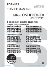
SERVICE MANUAL

SPLIT TYPE

INDOOR UNIT <DIGITAL INVERTER>

Compact 4-way Cassette Type

RAV-SM304MUT-E

RAV-SM304MUT-TR

RAV-SM404MUT-E

RAV-SM404MUT-TR

RAV-SM454MUT-E

RAV-SM454MUT-TR

RAV-SM564MUT-E

RAV-SM564MUT-TR

Concealed Duct Type

RAV-SM564BT-E

RAV-SM564BT-TR

RAV-SM804BT-E

RAV-SM804BT-TR

RAV-SM1104BT-E

RAV-SM1104BT-TR

RAV-SM1404BT-E

RAV-SM1404BT-TR

Ceiling Type

RAV-SM564CT-E

RAV-SM564CT-TR

RAV-SM804CT-E

RAV-SM804CT-TR

RAV-SM1104CT-E

RAV-SM1104CT-TR

RAV-SM1404CT-E

RAV-SM1404CT-TR

FILE NO. A10-031

Revision 1 : Dec., 2011

Revision 2 : Oct., 2014

AMP Air Conditioning

www.ampair.co.uk | [email protected]

Summary of Contents for RAV-SM404MUT-E

Page 1: ...AV SM564MUT E RAV SM564MUT TR Concealed Duct Type RAV SM564BT E RAV SM564BT TR RAV SM804BT E RAV SM804BT TR RAV SM1104BT E RAV SM1104BT TR RAV SM1404BT E RAV SM1404BT TR Ceiling Type RAV SM564CT E RAV SM564CT TR RAV SM804CT E RAV SM804CT TR RAV SM1104CT E RAV SM1104CT TR RAV SM1404CT E RAV SM1404CT TR FILE NO A10 031 Revision 1 Dec 2011 Revision 2 Oct 2014 AMP Air Conditioning www ampair co uk sal...

Page 2: ...ock Diagram 24 5 2 Control Specifications 27 5 3 Indoor Print Circuit Board 40 NOTE A direct current motor is adopted for indoor fan motor in the Concealed Duct Standard Type air conditioner Caused from its characteristics a current limit works on the direct current motor When replacing the high performance filter or when opening the service board be sure to stop the fan If an above action is exec...

Page 3: ...Set up Central Control Address Number 80 9 ADDRESS SETUP 82 9 1 Address Setup 82 9 2 Address Setup Group Control 83 9 3 Address Setup Manual Setting from Remote Controller 86 9 4 Confirmation of Indoor Unit No Position 87 10 DETACHMENTS 88 10 1 Compact 4 Way Cassette Type 88 10 2 Concealed Duct Type 97 10 3 Ceiling Type 100 11 EXPLODED VIEWS AND PARTS LIST 104 11 1 Compact 4 way Cassette Type 104 ...

Page 4: ...is thus thoroughly acquainted with the knowledge related to this work The qualified installer who is allowed to work at heights has been trained in matters relating to working at heights with the air conditioners made by Toshiba Carrier Corporation or alternatively he or she has been instructed in such matters by an individual or individuals who have been trained and is thus thoroughly acquainted ...

Page 5: ...om heat Insulating shoes Clothing to provide protection from electric shock Helmets for use in industry Shoes with additional protective toe cap Gloves to provide protection for electricians and from heat Indication DANGER WARNING CAUTION Explanation Indicates contents assumed that an imminent danger causing a death or serious injury of the repair engineers and the third parties when an incorrect ...

Page 6: ...s panel CAUTION Do not touch the aluminum fins of the unit Doing so may result in injury CAUTION BURST HAZARD Open the service valves before the operation otherwise there might be the burst Description WARNING ELECTRICAL SHOCK HAZARD Disconnect all remote electric power supplies before servicing WARNING Moving parts Do not operate unit with grille removed Stop the unit before the servicing CAUTION...

Page 7: ...ons Also wear a helmet for use in industry as protective gear to undertake the work When working at heights put a sign in place so that no one will approach the work location before proceeding with the work Parts and other objects may fall from above possibly injuring a person below Do not touch the aluminum fin of the outdoor unit You may injure yourself if you do so If the fin must be touched fo...

Page 8: ...ck that the ground wires are connected properly Be sure to connect earth wire Grounding work Incomplete grounding causes an electric shock Do not connect ground wires to gas pipes water pipes and lightning rods or ground wires for telephone wires Do not modify the products Do not also disassemble or modify the parts It may cause a fire electric shock or injury When any of the electrical parts are ...

Page 9: ...e refrigerant into the outdoor unit When the equipment is moved or repaired be sure to recover the refrigerant with recovering device The refrigerant cannot be recovered in the outdoor unit otherwise a serious accident such as breakage or injury is caused After repair work surely assemble the disassembled parts and connect and lead the removed wires as before Perform the work so that the cabinet o...

Page 10: ...er for the compressor or the area around this part to be repaired immediately after the air conditioner has been shut down set the circuit breaker to the OFF position and then wait at least 10 minutes before opening the service panel If you fail to heed this warning you will run the risk of burning yourself because the compressor pipes and other parts will be very hot to the touch In addition befo...

Page 11: ...ration of Conformity Manufacturer Toshiba Carrier Corporation 336 Tadehara Fuji shi Shizuoka ken 416 8521 JAPAN Authorized Nick Ball Representative TCF holder Toshiba EMEA Engineering Director Toshiba Carrier UK Ltd Porsham Close Belliver Industrial Estate PLYMOUTH Devon PL6 7DB United Kingdom Hereby declares that the machinery described below Generic Denomination Air Conditioner Model type RAV SM...

Page 12: ... RAV SM1404BT TR RAV SM564CT E RAV SM804CT E RAV SM1104CT E RAV SM1404CT E RAV SM564CT TR RAV SM804CT TR RAV SM1104CT TR RAV SM1404CT TR Sound power level dBA Cooling Heating Weight kg Main unit Ceiling panel 16 3 16 3 16 3 16 3 16 3 16 3 16 3 16 3 30 39 54 54 30 39 54 54 21 25 33 33 21 25 33 33 Under 70 dBA Other specifications than abo vementioned models are equal to current models 2 ser ies AMP...

Page 13: ... pipes are affected by impurities such as water oxide scales oil etc Use the clean pipes Be sure to brazing with flowing nitrogen gas Never use gas other than nitrogen gas 4 For the earth protection use a vacuum pump for air purge 5 R410A refrigerant is azeotropic mixture type refrigerant Therefore use liquid type to charge the refrigerant If using gas for charging composition of the refrigerant c...

Page 14: ...frigerant charge run check etc Vacuum evacuating Refrigerant charge Refrigerant charge Gas leakage check R410A air conditioner installation Existence of Whether conventional new equipment for R410A equipment can be used Yes Note Yes Note Yes No Yes No Yes No Yes Yes Yes No Yes No Conventional air conditioner installation Whether conventional equipment can be used Yes Note No No Yes Yes No Yes Note...

Page 15: ...h static pressure 2H tap Low static pressure H tap Standard L tap High static pressure 1H tap Standard H tap Low static pressure H tap Standard L tap High static pressure 1H tap Standard H tap Low static pressure H tap Standard L tap High static pressure 1H tap Standard H tap Low static pressure H tap Standard L tap High static pressure 1H tap Standard H tap Air volume limit Min Air volume limit M...

Page 16: ... 2H tap High static pressure 2H tap High static pressure 2H tap Low static pressure H tap Standard L tap High static pressure 1H tap Standard H tap Low static pressure H tap Standard L tap High static pressure 1H tap Standard H tap Low static pressure H tap Standard L tap High static pressure 1H tap Standard H tap Low static pressure H tap Standard L tap High static pressure 1H tap Standard H tap ...

Page 17: ...ocal arrange Wiring connection port For branch ductt knockout square hole Ø150 Knockout for flesh air intake Ø100 Electric parts box Ø162 For branch duct knockout square hole Ø150 Bottom face of ceiling Bottom face of ceiling Refrigerant pipe Gas Ø9 5 SM30 Ø12 7 SM40 45 56 Refrigerant pipe Liquid Ø6 4 268 27 63 134 145 5 220 5 1000 or more 1000 or more Obustacle 1000 or more 15 or more 15 or more ...

Page 18: ...inyl chloride pipe Inner dia 32 VP 25 41 196 393 498 638 50 131 243 50 Refrigerant pipe connecting port Gas side ØF 174 320 450 Plane view of main unit Check port A 100 300 Pipe side Discharge side NOTE 1 For maintenance of the equipment be sure to install a check port A at the position as shown below NOTE 2 Using the drain up kit sold separately drain up by 300 mm from drain pipe draw out port of...

Page 19: ... 19 2 3 Ceiling Type RAV SM564CT RAV SM804CT RAV SM1104CT RAV SM1404CT 250 or more 250 or more 500 or more AMP Air Conditioning www ampair co uk sales ampair co uk ...

Page 20: ... 20 3 WIRING DIAGRAM 3 1 Indoor Unit 3 1 1 Compact 4 way Cassette Type RAV SM304MUT RAV SM404MUT RAV SM454MUT RAV SM564MUT AMP Air Conditioning www ampair co uk sales ampair co uk ...

Page 21: ... 21 3 1 2 Concealed Duct Type RAV SM564BT RAV SM804BT RAV SM1104BT RAV SM1404BT AMP Air Conditioning www ampair co uk sales ampair co uk ...

Page 22: ... 22 3 1 3 Ceiling Type RAV SM564CT RAV SM804CT RAV SM1104CT RAV SM1404CT AMP Air Conditioning www ampair co uk sales ampair co uk ...

Page 23: ...sor TC sensor Float switch Drain pump motor Reactor Type ICF 280 120 1C ICF 280 120 2C 618 mm Ø6 mm 1200 mm Ø6 mm 1200 mm FS 0218 102 ADP 1409 CH 43 2Z T Specifications Output Rated 120 W 220 240 V Output Rated 120 W 220 240 V 10 kΩ at 25 C 10 kΩ at 25 C 10 kΩ at 25 C 10 mH 1 A No 1 2 3 4 5 6 7 8 Parts name Fan motor SM564CT Fan motor SM804CT Fan motor SM1104CT SM1404CT Thermo sensor TA sensor Hea...

Page 24: ... the simple wired remote controller Same as left 2 3 Follower A B A B Same as left 2 2 Follower A B DC5V DC5V Indoor unit 1 Heder Indoor control P C board MCC 1402 Louver motor Drain pump Indoor fan motor CPU H8 3039 Driver DC12V DC5V DC20V External output Remote controller communication circuit Display LCD Function setup Key switch CN2 CN1 3 CPU Display LED Display LCD LCD driver CPU Remote contr...

Page 25: ...ollower A B Indoor unit 1 Heder Indoor control P C board MCC 1402 Louver motor Drain pump Indoor fan motor CPU H8 3039 Driver DC12V DC5V DC20V A B External output Remote controller communication circuit Receive circuit Function setup SW CPU Buzzer Display LED DC5V Temporary operation SW Power circuit Remote controller communication circuit Power circuit DC280V Fan motor control circuit CPU TMP88CH...

Page 26: ...Indoor unit 1 Heder Indoor control P C board MCC 1402 Louver motor Drain pump Indoor fan motor CPU H8 3039 Driver DC12V DC5V DC20V External output Remote controller communication circuit Display LCD Function setup Key switch CN2 CN1 3 CPU Display LED Display LCD LCD driver CPU Power circuit Remote controller communication circuit Function setup Key switch Power circuit DC280V Fan motor control cir...

Page 27: ...ommand STOP FAN COOL DRY HEAT AUTO Control outline Air conditioner stops Fan operation Cooling operation Dry operation Heating operation COOL HEAT operation mode is automatically selected by Ta Ts and To for operation The operation is performed as shown in the following figure according to Ta value at the first time only In the range of Ts α 1 Ta Ts α 1 Cooling thermo OFF Fan Setup air volume oper...

Page 28: ...alculated to obtain the correction value of the frequency command and then the present frequency command is corrected Ts n Ta n Room temp difference n Counts of detection Ta n Ta n 1 Varied room temp value n 1 Counts of detection of 1 minute before 4 Dry operation The frequency correction control is same as those of the cooling operation However the maximum frequency is limited to approxi mately S...

Page 29: ...downward slope for the fan speed that is the high position If the temperature is just on the difference boundary the fan speed does not change Mode in the parentheses indicates one in automatic cooling operation HEAT Value in the parentheses indicates one when thermostat of the remote controller works Value without parentheses indicates one when thermostat of the body works If the fan speed has be...

Page 30: ...ing operation the revolution frequency of HH is set larger than that in the standard cooling heating operation However the revolution frequency is restricted in the automatic heating operation as shown in the following figure 6 Self clean operation When performing self clean operation after stopping the cooling operation the mode becomes 210 rpm 1 In heating operation the indoor fan is controlled ...

Page 31: ... and the operation returns to the normal operation If the commanded frequency becomes S0 because the operation continues in J zone the return temperature A is raised from 5 C to 12 C until I zone is detected and the indoor fan operates with L mode In heating operation the freeze preventive control works if 4 way valve is not exchanged and the following conditions are satisfied However the temperat...

Page 32: ...the operation or after operation start temperature is con trolled between values in parentheses of A and B 1 In cooling operation including Dry operation the drain pump is usually operated 2 If the float switch works while drain pump drives the compressor stops the drain pump continues the operation and a check code is output 3 If the float switch works while drain pump stops the compressor stops ...

Page 33: ... be set up collectively or individually 3 When the unit stopped or the warning was output the louver is automatically set to full closed position 4 When PRE HEAT Heating ready is displayed Heating operation started or defrost operation is performed heating thermo is off or self cleaning is performed the louver is automatically set to horizontal discharge position The louver which air direction is ...

Page 34: ...sitions can be set up collectively or individually 2 Swing setup The swinging position can be moved in the following operation range All modes In group operation the swinging positions can be set up collectively or individually 3 When the unit stops or when a warning is output the louver automatically moves downward 4 While the heating operation is ready or self cleaning the louver automatically m...

Page 35: ...set Remove the nameplate of the receiver unit and then turn the Dip switch to Test operation ON 2 The test operation starts by START STOP button START TIMER and READY LEDs flash during test operation Under condition of Test operation ON the temperature adjustment is invalid even if using the wireless remote controller Do not use it at other cases than a test operation because it applies excessive ...

Page 36: ... to set to 18 C to set to 30 C Then repeat the procedure 4 5 4 5 After approx 10 seconds all the display lamps on the sensor part of wireless remote controller Operation Green Timer Green and Ready Yellow flash and the air conditioner starts operation If the lamps do not flash repeat the procedure 2 and after After the test operation push Start Stop button to stop the operation Outline of test ope...

Page 37: ... controller the con tents to be operated are same though the display lamp does not change If an item prohibited by the central control mode is operated from the remote controller it is notified with receiving sound Pi Pi Pi Pi Pi 5 times 1 Selecting AUTO mode enables an energy saving to be operated 2 The setup temperature is shifted corrected in the range not to lose the comfort ability according ...

Page 38: ...yed on the wired remote controller screen via master unit If self clean operation is not used set invalidity does not use of the self clean operation by changing 0001 At shipment of CODE No DN D3 to 0000 To erase the display during operation of self clean change CODE No D4 from 0000 Display At shipment to 0001 Non display 1 Turn on SAVE button on the remote controller 2 During operation of save op...

Page 39: ...et temperature 6 To stop release this operation select and execute one from the following operations Q Push button Heating operation 18 C setting continues R Push START STOP button Air conditioner stops Heating 18 C operation at the next start S Push MODE Other operation mode is selected and the operation continues 7 As the setup temperature is 8 C and the human heating is not targeted the cold ai...

Page 40: ...ype Ceiling Type Fan output Optional output TC sensor HA T10 CHK DISP TA sensor Remote controller inter unit wire EXCT Used for servicing TCJ sensor Drain pump output Remote controller power supply LED Optional power supply Indoor Outdoor inter unit cable Filter Option error input EEPROM Connection interface Microcomputer operation LED AMP Air Conditioning www ampair co uk sales ampair co uk ...

Page 41: ...hermo ON Comp ON ON when operation mode is in cooling system COOL DRY COOL in AUTO cooling heating ON when operation mode is in heating system HEAT HEAT in AUTO cooling heating ON during indoor fan ON Air purifier is used Interlock cable When continued for 1 minute Check code L30 is output and forced operation stops Used for operation check of indoor unit Communication with outdoor unit or remote ...

Page 42: ...air volume changes Does not high temperature release operation control work in heating operation Does not outside low temperature operation control work in cooling operation Is not defrost operation performed 4 ON OFF operation cannot be performed from remote controller Is not automatic address being set up When the power is turned on at the first time or when indoor unit address setting is change...

Page 43: ...ontrol work in heating operation 3 Outdoor fan does not rotate or air volume changes Does not high temperature release operation control work in heating operation Does not outside low temperature operation control work in cooling operation Is not defrost operation performed 4 ON OFF operation cannot be performed from remote controller Is not forced operation performed Is not the control operation ...

Page 44: ...eceiving unit and indoor unit Duplicated indoor unit No Setup error Duplicated master units of remote controller Communication error between CPUs on indoor unit P C board Wire connection error between indoor units Indoor power OFF Communication stop between indoor header and follower Miswiring between indoor unit and outdoor unit or connection erorr Communication stop between indoor and outdoor un...

Page 45: ...p sensor TS error Temp sensor TH error Temp Sensor miswiring TE TS Indoor EEPROM error Outdoor EEPROM error Compressor break down Compressor lock Outdoor compressor system error 1 Current detection circuit error Case thermostat worked Outdoor unit low pressure system error Duplicated header indoor units There is indoor unit of group connection AUTO address in individual indoor unit If group constr...

Page 46: ... Ready Simultaneous flash Operation Timer Ready Alternate flash Check code Cause of trouble occurrence During test run Disagreement cool heat Automatic cool heat setting to automatic cool heat prohibited mode AMP Air Conditioning www ampair co uk sales ampair co uk ...

Page 47: ...stem communication receive error General purpose device control interface batched warning Group follower unit is defective Explanation of error contents Signal sending operation of central control system is impossible There are multiple same central devices AI NET Signal receiving operation of central control system is impossible An error on device connected to general purpose device control inter...

Page 48: ... Displayed when error is detected Displayed when error is detected Displayed when error is detected Displayed when error is detected Displayed when error is detected Displayed when error is detected Displayed when error is detected Displayed when error is detected Displayed when error is detected Displayed when error is detected Judgment and measures 1 Check cables of remote controller and communi...

Page 49: ...Stop Stop Stop Continue Stop Stop Stop Stop Stop Stop Stop Stop Stop Condition Displayed when error is detected Displayed when error is detected Displayed when error is detected Displayed when error is detected Displayed when error is detected Displayed when error is detected Displayed when error is detected Displayed when error is detected Displayed when error is detected Displayed when error is ...

Page 50: ...error of compressor 4 Check 4 way valve error 5 Check outdoor P C board error 1 Check service valves are fully opened Gas side Liquid side 2 Check clogging of outdoor PMV PMV1 2 3 Check SV2 circuit 4 Check Ps sensor error 5 Check clogging of indoor filter 6 Check clogging of refrigerant pipe 7 Check of outdoor fan operation In heating mode 8 Check short of refrigerant 1 Check refrigerating cycle G...

Page 51: ...conditioner Stop Stop Automatic reset If center exists operation continues Stop Automatic reset If center exists operation continues Stop Sub unit continues operation Stop Automatic reset Continues By remote controller Continuation Stop According to each case Condition Displayed when error is detected Displayed when error is detected Displayed when error is detected Displayed when error is detecte...

Page 52: ... connector on harness from terminal block of indoor unit Check power connection of indoor unit Turn on power again Check indoor P C board MCC 1402 Defect Replace Check remote controller P C board Defect Replace Correct as a header unit and a follower unit Check remote controller P C board Defect Replace Correct a header unit a follower unit Remote controller address connector Correct connection of...

Page 53: ...rrect lines Check and eliminate noise etc Check outdoor P C board Defect Replace Correct wiring of connector and terminal blocks Correct wiring and inter unit cables Check CODE No 14 YES YES YES YES YES NO NO NO NO NO NO As shown in the following figure carry out measurement within 20 seconds after the power was turned on Black S5277G White Terminal block Check indoor P C board MCC 1402 Defect Rep...

Page 54: ...tatus of indoor unit Connect again Correct connection of connector Check circuit wiring Correct inter unit cable of remote controller YES YES Is connection twin triple connection YES YES YES YES NO NO NO NO NO NO E18 error E08 L03 L07 L08 error E08 Duplicated indoor unit No L03 There are 2 or more header units in a group control L07 There is 1 or more group address Individual in a group control L0...

Page 55: ...emote controller Are wiring connections to communication lines U3 and U4 normal Check central controller including 1 1 model connection interface and indoor P C board MCC 1402 Defect Replace Correct wiring connection Correct central control system address Check indoor P C board MCC 1402 Defect Replace Check outside devices Defect Replace Check indoor P C board MCC 1402 Defect Replace YES YES YES Y...

Page 56: ...t connection of connector Check indoor P C board MCC 1402 Defect Replace Check and correct wiring and wire circuit YES YES YES YES YES YES NO NO NO NO NO NO Is connection of TAsensor connector indoor P C board CN104 nornal Connect connector of connector Check indoor P C board MCC 1402 Defective Replace Are characteristics of TA sensor resistance value normal Replace TA sensor NO YES Refer to Chara...

Page 57: ...with hands and check the pin voltage swings between 0 to 5V voltage Between and 5V Check indoor P C board MCC 1402 Defect Replace Remove connectors CN333 and CN334 of indoor unit P C board MCC 1402 Replace indoor fan motor Replace indoor fan motor Replace indoor fan motor YES NO NO NO NO NO YES YES YES YES Turn off the power Is resistance value of fan motor connector CN333 at motor side of indoor ...

Page 58: ...2 1 ON 4 1 4 Operation check direction of the outdoor P C board In case of self preservation valve 1 Set the Dip switch SW804 as same as the following table and push SW801 for approx 1 second It enables you to check the exchange operation to cooling cycle or heating cycle Only for approx 10 seconds the power is turned on As the heat value of part coil resistance R700 is large when checking the ope...

Page 59: ...e TC sensor Check indoor P C board MCC 1402 Defect Replace Correct connection of connector Are characteristics of TCJ sensor resistance value normal Is connection of TCJ sensor connector CN102 on Indoor P C board correct Refer to Charqacteristics 2 Replace TCJ sensor Check indoor P C board MCC 1402 Defect Replace YES YES YES YES NO NO NO NO F01 error AMP Air Conditioning www ampair co uk sales amp...

Page 60: ...n line of remote controller 1 Is connection of connector normal Check the power supply transformer of 1 1 model connection interface MCC 1440 Defective Replace Can the other indoor units be normally controlled from the central controller Or is the operation status of indoor unit reflected 1 In case of 1 1 model connection interface 1 1 model connection interface MCC 1440 CN51 and indoor P C board ...

Page 61: ... air conditioner Replace the service P C board When EEPROM was not inserted when power supply turned on or when the EEPROM data read write operation is impossible at all the automatic address mode is repeated In this time 97 error is displayed on the central controller P31 error Follower indoor unit When the master unit of a group operation detected E03 L03 L07 or L08 error the follower unit of th...

Page 62: ...erature C Resistance kΩ 0 0 50 100 150 200 0 5 10 15 20 10 20 30 40 50 60 70 80 90 100 Temperature C Temperature Resistance value characteristic table Temperature C 0 10 20 25 30 40 50 60 70 80 90 100 Resistance value kΩ Ω Ω Ω Ω Minimum Standard Maximum value value value 150 5 161 3 172 7 92 76 99 05 105 6 58 61 62 36 66 26 47 01 49 93 52 97 37 93 40 22 42 59 25 12 26 55 28 03 17 00 17 92 18 86 11...

Page 63: ...R RAV SM1104CT RAV SM1404CT Position Black Red Black White Red White Resistance value 87 8 7 87 8 7 87 8 7 Under 20 C Measure the resistance value of each winding by using the tester Fan motor inside wiring diagram Measure the resistance value of each winding by using the tester Fan motor inside wiring diagram Position Black Red Black White Red White Resistance value 23 4 2 4 23 4 2 4 23 4 2 4 Und...

Page 64: ...nnected to the remote control when the group operation control is performed CASE 2 Before replacement the indoor unit cannot be turned on or the wired remote controller operation is impossible due to trouble of the power supply circuit to the remote controller Defective P C board Replacement of EEPROM Remove EEPROM installed on the P C board before replacement and then replace it with EEPROM of th...

Page 65: ... indoor unit belongs to or whether the indoor unit works as the header unit or the follower unit in the group control operation 1 Setting data read out from EEPROM The setting data modified on the site other than factory set value stored in the EEPROM shall be read out Step 1 Push SET CL and TEST button on the remote controller simultaneously for more than 4 seconds When the group operation contro...

Page 66: ...ting 5 Select the capacity by pushing buttons for the timer setting For example 80 Type is set to 0012 Refer to table 3 6 Push SET button The setting completes if the setting data are displayed 7 Return to the normal stop status by pushing TEST button Approx 1 minute is needed to start operation of the remote controller Step 5 Write the on site setting data to the EEPROM such as address setting et...

Page 67: ...t Auto restart after power failure Thermo output SW T10 e Ventilation fan standalone Sensor select Selection of static pressure Drain pump control Timer setting wired remote controller DEMAND setup Remote controller save function Frost protection function Revolutions per minute of dry operation Setting data Factory set value Depending on Type 0000 standard 0099 Not determined 0002 2 C 0000 Heat pu...

Page 68: ...remote controller Compact 4 way Cassette Type and Concealed Duct Type 1 Remove a screw which fixes the serial olate of the receiver part on the wireless remote controller Remove the nameplate of the reciver section by inserting a minus screwdriver etc into the notch at the bottom of the plate and set the Dip switch to TEST RUN ON 2 Execute a test operation with button on the wireless remote contro...

Page 69: ... button to set to 19 C push Temperature set button to set to 29 C After checking the receiving sound Pi immediately After checking the receiving sound Pi immediately push Temperature set button to set to 18 C push Temperature set button to set to 30 C Then repeat the procedure 4 5 4 5 After approx 10 seconds all the display lamps on the sensor part of wireless remote controller Operation Green Tim...

Page 70: ...s the status to the normal stop status Practical operation Push ON OFF ON OFF Key Select the HEAT mode After while the forced defrost signal is sent to the outdoor unit and then the outdoor unit starts defrost operation The forced defrost operation is performed for Max 12 minutes After defrost operation finished the operation returns to the heating operation To execute the defrost operation again ...

Page 71: ...elected indoor unit operate Ø 2 Every pushing UNIT LOUVER button button at left side the indoor unit No in the group control is displayed one after the other In this time fan and louver of the selected indoor unit only operate Ø 3 Using the set temperature TEMP buttons specify the CODE No DN Ø 4 Using the timer time TIME buttons select the set data Ø 5 Push SET button OK if indication lights To ch...

Page 72: ... 0006 40 type 0007 45 type 0009 56 type 0012 80 type 0015 110 type 0017 140 type 0001 No 1 unit to 0030 No 30 unit 0001 No 1 unit to 0064 No 64 unit 0000 Individual 0001 Master of group 0002 Follower of group 0000 No louver 0001 Swing only 0002 1 way 0003 2 way 0004 4 way 0000 0 deg to 0010 10 deg For setup temperature reversal of COOL HEAT by Data value 2 0000 None 0001 Auto restart 0000 Indoor t...

Page 73: ... is 10 to 60 minutes is set up When ON time is over 60 minutes the operating time becomes two times of it 0050 50 to 0100 100 0000 None 0001 Set When stopping the air conditioner including Fire alarm of the control system etc while START STOP operation is prohibited Central 1 2 from the central controller side 0000 Valid No self cleaning 0001 Invalid Self cleaning 0000 Invalid Unavailable 0001 Val...

Page 74: ...y 2 1 3 2 1 3 B A B A B A Sold separately Terminal block for remote controller cables Indoor unit 1 Outdoor unit Remote controller switch Sub Remote controller switch Master Sold separately 2 1 3 2 1 3 B A B A B A Indoor unit 2 2 1 3 B A Sold separately Remote controller inter unit wire Procured locally Inter unit wiring between indoor units Procured locally 1 2 3 4 ON ON S003 Bit 3 OFF ON 1 2 3 4...

Page 75: ...turns the status to the usual display The data value of each item is not the real time but value delayed by a few seconds to ten odd seconds If the combined outdoor unit is one before 2 or 3 series the outdoor unit data 6D 70 72 and 73 are not displayed Indoor unit data CODE No 01 02 03 04 07 F2 F3 F8 Data name Room temperature Remote controller Indoor suction temperature TA Indoor heat exchanger ...

Page 76: ...o setting on the remote controller System example 1 Display range on remote controller The setup range Operation mode Air volume select Setup temp of the indoor unit which was set to the header unit is reflected on the remote controller 1 Concealed duct high static pressure type RAV SMXXX is not set up on the header unit If the Concealed duct high static pressure type is the header unit Operation ...

Page 77: ...le Approx 50 seconds after power ON Regular communication between indoor units Every 30 seconds Header Follower Regular communication of the identical piping system Every 30 seconds Twin header follower When the above status changes immediately communicates Repetition The unit without power feed waits entirely Waiting status is released by system start Reboot when power is fed on the way 3 minutes...

Page 78: ...l system wiring Header unit Header unit Follower unit Follower unit Follower unit Wiring for No 1 and 2 only Caution 2 Remote controller Remote controller Remote controller Remote controller wiring Group operation Max 8 units Twin Triple operation Example of triple 8 2 Setup at Local Site Others Model name TCB PCNT30TLE 8 2 1 1 1 Model Connection Interface TCC LINK adapter 1 Function This model is...

Page 79: ...m wiring Header unit Header unit Follower unit Follower unit Follower unit Caution 2 Remote controller Remote controller Remote controller Group operation Triple operation Caution 3 1 1 model connection interface TCC LINK adapter This option Earth screw Central control device U1 U3 U2 U4 Central control device U1 U3 1 2 3 U2 U4 Central control devices Max 10 units Refrigerant line 1 Outdoor unit I...

Page 80: ...played and all the indoor units in the group control are selected In this time fans of all the selected indoor units are turned on Fig 1 Keep displayed status without pushing UNIT LOUVER button In case of individual remote controller which is not group controlled Line address and Indoor unit address are displayed 2 Using temperature setup TEMP buttons specify CODE No 03 03 03 03 03 3 Using timer t...

Page 81: ...immediately the display disappears and then the pushed button is displayed How to confirm the central control address New function for AMT32E remote controller Procedure It can be confirmed even during operation or stopping 1 Push UNIT LOUVER button for 4 seconds or more Ø 2 In the frame at left side of the remote controller screen the lighting set contents are displayed During unset time 0099 009...

Page 82: ...or unit are connected and they are twin triple or when an outdoor unit is connected to each indoor unit respectively in the group operation even if multiple refrigerant lines are provided the automatic address setup completes with power ON of the outdoor unit The operation of the remote control ler is not accepted while automatic address works Approx 4 to 5 minutes When the following addresses are...

Page 83: ...t This unit communicates with the indoor unit sub which serial communicates with the Representative unit outdoor units and sends receives signal Command from compressor to from the outdoor Header Twin units as the representative of the cycle control in the indoor units of the identical line address within the minimum unit which configures one of the refrigerating cycles of Twin Triple Double twin ...

Page 84: ...nit The sub unit receives the indoor unit data from the master With identical line address indoor outdoor serial and then performs the thermo operation synchronized with the master unit The sub unit sends own thermo ON OFF demand to the master unit Example No 1 1 master unit sends receives signal to from No 1 2 and No 1 3 sub units It is not influenced by the line 2 or 3 address indoor unit 2 1 He...

Page 85: ... 1 1 2 1 1 Follower Sub 9 2 2 Automatic Address Example from Unset Address No miswiring 1 Standard One outdoor unit Only turning on source power supply Automatic completion 2 Group operation Multiple outdoor units Multiple indoor units with serial communication only without twin Only turning on source power supply Automatic completion 3 Multiple groups operation Change is necessary Manually change...

Page 86: ...ote Controller In case that addresses of the indoor units will be determined prior to piping work after wiring work Set an indoor unit per a remote controller Turn on power supply 1 Push SET CL TEST buttons simultaneously for 4 seconds or more 2 Line address Using the temperature setup buttons set 12 to the CODE No 3 Using timer time buttons set the line address 4 Push SET button OK when display g...

Page 87: ...ler Group control unit other unit numbers are also displayed every pushing UNIT LOUVER button 2 To know the position of indoor unit body by address To confirm the unit No in the group control Follow to the procedure during operation in this procedure the indoor units in group control stop Procedure The indoor unit numbers in the group control are successively displayed and fan louver and drain pum...

Page 88: ...Slide the fixing bracket toward the outside 3 Slide the air intake grille buttons to detach the air intake grille from the ceiling panel Lower the grille slowly whilst holding 4 Slide hooks 2 positions of the suction grille to inner side and then hang down the suction grille 5 Take off the strap that connects the panel and the suction grille and then lift up shaft of the suction grille to remove t...

Page 89: ...ust corner cover rises up NOTE When you work keep the torque at below 12N m Do not use an electric screwdriver otherwise the mechanism of adjust corner cover may be damaged and not be removed 3 Pull downward the risen up part of adjust corner cover and remove it 4 Remove the strap of adjust corner cover 2 Attachment 1 Attach the strap of adjust corner cover to the panel hook claws of adjust corner...

Page 90: ...hment 1 Hook the panel to the temporary bracket of the drain pan of the main body NOTE The panel has directionality Therefore mount the panel according to the temporary bracket and the bracket mounting position 2 Tighten the fixing screws M5 4 pcs 3 Connect flap connector of the ceiling panel to the connector CN33 White 5P of the control P C board Hanging section of tentative hook of ceiling panel...

Page 91: ... remote controller Be careful that other sensor does not fall out Adhere on the transformer Cord clamp Arrow view E E No 5 Part name Control P C board Procedure 1 Detachment 1 Perform works of procedure 1 1 and 2 1 2 Remove the connectors connected from the control P C board to other parts CN33 Louver motor 5P White CN34 Float switch 3P Red CN41 Terminal block of remote controller 3P Blue CN40 Ter...

Page 92: ...e controller Be careful that other sensor does not fall out Adhere on the transformer Cord clamp Arrow view E E No 6 Part name Electric parts box Procedure 1 Detachment 1 Perform works of procedure 1 1 and 2 1 2 Remove connectors of the lead wire connected to the following connectors of the control P C board CN33 Louver motor 5P White CN34 Float switch 3P Red CN68 Drain pump 3P Blue CN101 TC2 sens...

Page 93: ...oved NOTE Pinch lead wire of the drain pump and float switch with lead wire fixing claws of the bell mouth and perform wiring along the guide 1 Detachment 1 Perform work of procedure 7 1 2 Take off the nut M6 nut 1 pc of the turbo fan NOTE Use a box wrench for attachment and detachment of the turbo fan If using a monkey wrench etc the other parts may be damaged in work 2 Attachment 1 Insert the tu...

Page 94: ...achment of the fan motor fixing nuts otherwise contact or damage for other parts may be caused 2 Attachment 1 Mount the fan motor with the fixing nuts NOTE Tightening torque of turbo fan 5 9 0 6N m Apply looseness preventing agent as paints to the nut after tightening 2 Attach the fan motor lead wire holder NOTE For the fan motor lead wire fix the lead wire holding bracket along concave part of th...

Page 95: ...il it strikes on the socket of the drain pan 2 Draw each lead wire to the correct positions and then insert the drain pan into the main unit NOTE Draw lead wires of the drain pump and the float switch along the guide of the cabinet Insert the drain pan along the guides of sensors TC1 TC2 TCJ and PMV lead wire The drain pan and each lead wire are not caught in otherwise water leakage may be caused ...

Page 96: ...oor unit side 3 Perform work of procedure 10 1 4 Take off screws Ø4 10 3 pcs fixing the piping cover to remove the piping cover 5 While holding the heat exchanger remove fixing band and fixing screws Ø4 10 3 pcs and then remove the heat exchanger 2 Attachment 1 Mount parts in order heat exchanger fixing band piping cover drain pan bell mouth electric parts box as original NOTE Arrange wires as ori...

Page 97: ...ectrical parts box 5 Remove the electrical parts box The electrical parts box is fixed to the main unit with claws at the right side Lift up it once and pull toward you Then claws come off In this time remove connectors of TA sensor TC sensor and TCJ sensor if necessary 1 Remove the air filter 2 Remove the connector of the fan motor P C board 3 Remove the hexagon head screw 562 2 802 1102 1402 3 p...

Page 98: ...Remove the fan motor holder 2 positions 1 Take down the main unit and then treat the drain pan on the floor 2 Remove the set screws 562 7 802 1102 1402 9 positions of fixing lower plate 3 Remove the lower plate from main unit 4 Remove the set screws 562 Nothing 802 2 positions 1102 1402 4 positions of fixing drain pan holder and main unit 5 Remove the drain pan holder 562 Nothing 802 1 position 11...

Page 99: ...set screws 3 positions of fixing drain pump plate and main unit 3 Remove the set screws 3 positions of fixing drain pump plate and drain pump 1 Remove the set screws 5 positions and check port cover right side 2 Pull out the sensor is inserted into pipe of the heat exchanger 1 Take down the main unit and then treat the heat exchanger on the floor 2 Remove the drain pan 3 Remove the check port cove...

Page 100: ... filter 2 Slide the suction grille fixing knobs 2 positions toward the arrow direction of left figure and open the suction grille 3 Under the condition of the suction grille opened push the hook section of hinges 2 positions at the rear side and then pull out the suction grille 1 Open the suction grille 2 After removing the side panel screws 2 positions slide the side panel forward and then remove...

Page 101: ...SM1102 SM1402CT E only Remove the set screw 1 position to fixing and reinforcing bar Slide the reinforcing bar toward arrow side on the left figure 4 Push the fan cover fixing hooks 2 positions forward fan cover side and remove the fan cover 5 SM1102 SM1402CT E only Remove the hexagon head screws 2 positions to fix bearing and the bearing 6 Remove the hexagon head screw of fixing fan motor and fan...

Page 102: ... SM1102 SM1402CT E only Remove the set screw 1 position to fixing and reinforcing bar Slide the reinforcing bar toward arrow side on the right figure 4 Remove the set screws 9 positions of fixing lower plate 5 Remove the heat insulation on the drain pan SM562 SM802 1 position SM1102 SM1402 2 positions 6 Remove the set screws SM562 SM802 1 position SM1102 SM1402 2 positions of fixing drain pan and ...

Page 103: ...e center shaft SM562 SM802 1 position SM1102 SM1402 2 positions from louver holder 2 Pull off the left and right chaft of horizontal louver 1 Remove the drain pan 2 Remove the set screws 4 positions and heat exchanger support 3 Pull out the sensor is inserted into pipe of the heat exchanger 1 Take down the main unit and then treat the heat exchanger on the floor 2 Remove the drain pan 3 Remove the...

Page 104: ...31 201 236 209 203 205 247 233 224 241 240 238 239 ᵲᵣᵱᵲ 24 5 6 0 1 37 6 59 0 5 2 1 146 219 4 6 4 10 1 6 4 1 TOSHIBA 6 2 4 5 6 5 2 11 EXPLODED VIEWS AND PARTS LIST 11 1 Compact 4 way Cassette Type RAV SM304MUT E RAV SM304MUT TR AMP Air Conditioning www ampair co uk sales ampair co uk ...

Page 105: ...SSY TURBO BELLMOUTH PAN ASSY DRAIN MOTOR FAN REFRIGERATION CYCLE ASSY DISTRIBUTOR ASSY NUT FLARE 1 4 IN SOCKET NUT FLARE 3 8 IN SOCKET BONNET BONNET HOSE DRAIN BAND HOSE FILTER NOISE HOLDER LEAD FAN MOTOR HOSE DRAIN COVER PIPE NUT HOLDER SENSOR TS BAND HOSE RUBBER CUSHION COVER E BOX PUMP DRAIN SWITCH FLOAT RUBBER PUMP DRAIN REMOTE CONTROLLER REMOTE CONTROLLER REMOTE CONTROLLER REMOTE CONTROLLER W...

Page 106: ...E RAV SM454MUT E RAV SM564MUT E 234 230 215 213 220 219 216 217 211 227 225 242 226 222 237 235 202 223 221 228 231 201 236 209 203 205 247 233 224 238 239 241 240 AMP Air Conditioning www ampair co uk sales ampair co uk ...

Page 107: ...483 COVER PIPE 228 43097212 NUT 230 43019904 HOLDER SENSOR TS 231 43179135 BAND HOSE 233 43139137 RUBBER CUSHION 234 43162056 COVER E BOX 235 43177001 PUMP DRAIN 236 43151289 SWITCH FLOAT 237 43179126 RUBBER PUMP DRAIN 238 43166011 REMOTE CONTROLLER SX A4EE 239 43166012 REMOTE CONTROLLER SX A5EE 240 43166004 REMOTE CONTROLLER SX A11JE2 241 43166006 REMOTE CONTROLLER WH H1JE2 242 431S8221 OWNER S M...

Page 108: ...83 COVER PIPE 228 43097212 NUT 230 43019904 HOLDER SENSOR TS 231 43179135 BAND HOSE 233 43139137 RUBBER CUSHION 234 43162056 COVER E BOX 235 43177001 PUMP DRAIN 236 43151289 SWITCH FLOAT 237 43179126 RUBBER PUMP DRAIN 238 43166011 REMOTE CONTROLLER SX A4EE 239 43166012 REMOTE CONTROLLER SX A5EE 240 43166004 REMOTE CONTROLLER SX A11JE2 241 43166006 REMOTE CONTROLLER WH H1JE2 242 431S8222 OWNER S MA...

Page 109: ...ERVICE TC 402 43050426 SENS0R SERVICE TA 403 4316V461 PC BOARD ASSY MCC 1402 404 43160568 TERMINAL 2P 405 43160565 TERMINAL BLOCK 3P 20A Model name RAV SM 404MUT E TR 304MUT E TR 454MUT E TR 564MUT E TR 2 1 1 1 1 2 1 1 1 1 2 1 1 1 1 2 1 1 1 1 AMP Air Conditioning www ampair co uk sales ampair co uk ...

Page 110: ...215 228 232 202 203 902 905 204 206 906 223 226 231 227 216 229 242 217 207 240 241 238 236 237 239 11 2 Concealed Duct Type RAV SM564BT E RAV SM564BT TR AMP Air Conditioning www ampair co uk sales ampair co uk ...

Page 111: ...SE DRAIN 231 43172168 PAN ASSY DRAIN 232 43179110 PLUG 234 43180311 AIR FILTER 236 43166011 REMOTE CONTROLLER SX A4EE 237 43166012 REMOTE CONTROLLER SX A5EE 238 43166004 REMOTE CONTROLLER SX A11JE2 239 43166006 REMOTE CONTROLLER WH H1JE2 240 431S8224 OWNER S MANUAL 241 431S8223 OWNER S MANUAL 242 43196012 BUSHING 902 43149351 SOCKET 905 43047688 NUT FLARE 1 2 IN 906 43149353 SOCKET Model name RAV ...

Page 112: ... 112 RAV SM804BT E RAV SM804BT TR 224 235 234 232 233 210 220 223 222 219 211 212 221 230 204 218 202 203 904 905 901 902 903 216 228 229 AMP Air Conditioning www ampair co uk sales ampair co uk ...

Page 113: ...PLUG 224 43180312 AIR FILTER 228 431S8224 OWNER S MANUAL 229 431S8223 OWNER S MANUAL 230 43196012 BUSHING 232 43166011 REMOTE CONTROLLER SX A4EE 233 43166012 REMOTE CONTROLLER SX A5EE 234 43166004 REMOTE CONTROLLER SX A11JE2 235 43166006 REMOTE CONTROLLER WH H1JE2 901 43049776 SOCKET 902 43194029 BONNET 903 43149355 NUT FLARE 3 8 IN 904 43149352 NUT FLARE 5 8 IN 905 43149354 SOCKE Model name RAV S...

Page 114: ... E RAV SM1404BT E RAV SM1104BT TR RAV SM1404BT TR 210 222 225 224 214 215 221 211 223 232 213 212 226 204 220 202 203 904 901 902 903 219 230 231 234 235 236 237 AMP Air Conditioning www ampair co uk sales ampair co uk ...

Page 115: ...FILTER 230 431S8224 OWNER S MANUAL 231 431S8223 OWNER S MANUAL 232 43196012 BUSHING 234 43166011 REMOTE CONTROLLER SX A4EE 235 43166012 REMOTE CONTROLLER SX A5EE 236 43166004 REMOTE CONTROLLER SX A11JE2 237 43166006 REMOTE CONTROLLER WH H1JE2 901 43049776 SOCKET 902 43194029 BONNET 903 43149355 NUT FLARE 3 8 IN 904 43149352 NUT FLARE 5 8 IN Model name RAV SM 1104BT E 1404BT E 1104BT TR 1404BT TR 2...

Page 116: ...E TA 403 43158193 REACTOR CH 43 2Z T 404 43160565 TERMINAL BLOCK 3P 20A 405 4316V462 PC BOARD ASSY MCC 1402 406 43155203 CAPACITOR KIT SERVICE 407 43160568 TERMINAL 2P Model name RAV SM 564BT E 804BT E 1104BT E 1404BT E TR TR TR TR 2 2 2 2 1 1 1 1 1 1 1 1 1 1 1 1 1 1 1 1 1 1 1 1 1 1 1 1 AMP Air Conditioning www ampair co uk sales ampair co uk ...

Page 117: ...8 209 249 227 228 SM56 Fan assembly SM80 Fan assembly 217 225 43 41 260 261 210 240 226 258 236 237 238 239 254 255 222 223 224 233 234 235 253 256 257 247 248 266 201 202 203 244 245 246 214 217 225 252 227 229 204 205 206 265 251 262 230 212 213 250 212 259 268 220 218 219 221 AMP Air Conditioning www ampair co uk sales ampair co uk ...

Page 118: ...RIBUTOR A SSY 224 43147702 DISTRIBUTOR A SSY 225 43122084 CASE FAN LOWER 226 43122085 CASE FAN UPPER 227 43180314 AIR FILTER 228 43180315 AIR FILTER 229 43108014 BASE RECEIVER 230 43179136 BAND HOSE 231 43125131 BEARING SHAFT 232 43125162 COUPLING 233 43047685 NUT FLARE 1 4 IN 234 43049776 SOCKET 235 43149351 SOCKET 236 43047688 NUT FLARE 1 2 IN 237 43149352 NUT FLARE 5 8 IN 238 43149353 SOCKET 23...

Page 119: ...STRIBUTOR A SSY 224 43147702 DISTRIBUTOR A SSY 225 43122084 CASE FAN LOWER 226 43122085 CASE FAN UPPER 227 43180314 AIR FILTER 228 43180315 AIR FILTER 229 43108014 BASE RECEIVER 230 43179136 BAND HOSE 231 43125131 BEARING SHAFT 232 43125162 COUPLING 233 43047685 NUT FLARE 1 4 IN 234 43049776 SOCKET 235 43149351 SOCKET 236 43047688 NUT FLARE 1 2 IN 237 43149352 NUT FLARE 5 8 IN 238 43149353 SOCKET ...

Page 120: ...160565 TERMINAL BLOCK 3P 20A 405 4316V461 PC BOARD ASSY MCC 1402 406 43155203 CAPACITOR KIT SERVICE 407 43160568 TERMINAL 2P Model name RAV SM 564CT E 804CT E 1104CT E 1404CT E TR TR TR TR 2 2 2 2 1 1 1 1 1 1 1 1 1 1 1 1 1 1 1 1 1 1 1 1 1 1 1 1 403 401 407 406 404 405 402 Electric parts AMP Air Conditioning www ampair co uk sales ampair co uk ...

Page 121: ... 2 Cover Page 11 12 17 20 Page 67 72 104 105 109 Compact 4 way Cassette type SM30 was added Oct 2014 TOSHIBA CARRIER CORPORATION 72 34 Horikawa cho Saiwai ku Kawasaki shi Kanagawa 212 8585 JAPAN Copyright 2014 TOSHIBA CARRIER CORPORATION ALL Rights Reserved AMP Air Conditioning www ampair co uk sales ampair co uk ...

Reviews: