background image


 [CONFIDENTIAL] 


Toshiba Personal Computer 

PORTÉGÉ M500 

Maintenance Manual 


TOSHIBA CORPORATION


File Number 960-559 


Summary of Contents for Portege M500

Page 1: ... CONFIDENTIAL Toshiba Personal Computer PORTÉGÉ M500 Maintenance Manual TOSHIBA CORPORATION File Number 960 559 ...

Page 2: ...is manual s production However succeeding computers and manuals are subject to change without notice Therefore Toshiba assumes no liability for damages incurred directly or indirectly from errors omissions or discrepancies between any succeeding product and this manual Trademarks IBM is a registered trademark and IBM PC is a trademark of International Business Machines Corporation Intel Intel Spee...

Page 3: ...e of a hazard that could result in bodily injury if the safety instruction is not observed CAUTION Caution indicates the existence of a hazard that could result in property damage if the safety instruction is not observed NOTE Note contains general information that relates to your safe maintenance service Improper repair of the computer may result in safety hazards Toshiba requires service technic...

Page 4: ...ose and resolve FRU problems Chapter 3 Test and Diagnostics describes how to perform test and diagnostic operations for maintenance service Chapter 4 Replacement Procedures describes the removal and replacement of the FRUs Appendices The appendices describe the following Handling the LCD module Board layout Pin assignments Keyboard scan character codes Key layout Wiring diagrams BIOS rewrite proce...

Page 5: ...pears on the keyboard is printed in boldface type Key operation Some operations require you to simultaneously use two or more keys We identify such operations by the key top symbols separated by a plus sign For example Ctrl Pause Break means you must hold down Ctrl and at the same time press Pause Break If three keys are used hold down the first two and at the same time press the third User input ...

Page 6: ...2 Troubleshooting Flowchart 2 3 2 3 Power Supply Troubleshooting 2 7 2 4 System Board Troubleshooting 2 19 2 5 USB FDD Troubleshooting 2 36 2 6 HDD Troubleshooting 2 39 2 7 Keyboard and Touch pad Troubleshooting 2 44 2 8 Display Troubleshooting 2 47 2 9 Optical Drive Troubleshooting 2 49 2 10 Modem Troubleshooting 2 51 2 11 LAN Troubleshooting 2 53 2 12 Bluetooth Troubleshooting 2 54 2 13 Wireless...

Page 7: ... 12 Async Test 3 25 3 13 Hard Disk Test 3 26 3 14 Real Timer Test 3 29 3 15 NDP Test 3 31 3 16 Expansion Test 3 32 3 17 CD ROM DVD ROM Test 3 34 3 18 Error Code and Error Status Names 3 35 3 19 Hard Disk Test Detail Status 3 38 3 20 ONLY ONE TEST 3 40 3 21 Head Cleaning 3 47 3 22 Log Utilities 3 48 3 23 Running Test 3 50 3 24 Floppy Disk Drive Utilities 3 51 3 25 System Configuration 3 56 3 26 Wir...

Page 8: ... 4 12 SW membrane 4 32 4 13 Bluetooth module 4 34 4 14 Wireless LAN card 4 36 4 15 MDC Modem Daughter Card 4 38 4 16 Internal microphone 4 40 4 17 RTC battery 4 42 4 18 Harness holder LAN cable 4 44 4 19 System board DC IN jack 4 47 4 20 Modem jack Wireless communication SW 4 50 4 21 Fan CPU 4 53 4 22 HDD cable PC card slot 4 57 4 23 LCD unit FL inverter 4 59 4 24 Speaker LCD cable 4 65 4 25 Cover...

Page 9: ... the LCD Module A 1 Appendix B Board Layout B 1 Appendix C Pin Assignments C 1 Appendix D Keyboard Scan Character Codes D 1 Appendix E Key Layout E 1 Appendix F Wiring Diagrams F 1 Appendix G BIOS rewrite Procedures G 1 Appendix H EC KBC rewrite Procedures H 1 Appendix I Reliability I 1 ...

Page 10: ...x CONFIDENTIAL PORTÉGÉ M500 Maintenance Manual 960 559 ...

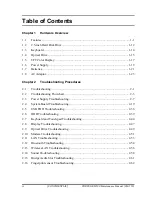
Page 11: ... CONFIDENTIAL Chapter 1 Hardware Overview ...

Page 12: ...1 Hardware Overview 1 ii CONFIDENTIAL PORTÉGÉ M500 Maintenance Manual 960 559 ...

Page 13: ... 5 inch Hard Disk Drive 1 12 1 3 Keyboard 1 14 1 4 Optical Drive 1 15 1 4 1 DVD ROM CD R RW Drive 1 15 1 4 2 DVD Super Multi Drive 1 16 1 5 TFT Color Display 1 17 1 5 1 LCD Module 1 17 1 5 2 FL Inverter Board 1 18 1 6 Power Supply 1 19 1 7 Batteries 1 21 1 7 1 Main Battery 1 21 1 7 2 RTC battery 1 22 1 8 AC Adaptor 1 23 ...

Page 14: ...able 1 1 2 5 inch HDD specifications 1 12 Table 1 2 DVD ROM CD R RW drive specifications 1 15 Table 1 3 DVD Super Multi drive specifications 1 16 Table 1 4 LCD module specifications 1 17 Table 1 5 FL inverter board specifications 1 18 Table 1 6 Power supply output rating 1 20 Table 1 7 Battery specifications 1 21 Table 1 8 Time required for charges 1 21 Table 1 9 Data preservation time 1 22 Table ...

Page 15: ...ch model and options Microprocessor The PORTÉGÉ M500 computer is equipped with one of the following processors Intel CoreTM Duo CoreTM Duo 1 66GHz Processor Number T2300 1 83GHz Processor Number T2400 2 00GHz Processor Number T2500 2 16GHz Processor Number T2600 2 33GHz Processor Number T2700 Intel CoreTM Solo CoreTM Solo 1 66GHz Processor Number T1300 1 83GHz Processor Number T1400 Intel Celeron ...

Page 16: ...alled Display LCD Built in 12 1 inch 16M colors WXGA 1280 800dots thin type low temperature poly silicon TFT color display External monitor Supported via an RGB connector Keyboard An easy to use 84 US 85 UK key keyboard provides a numeric keypad overlay for fast numeric data entry or for cursor and page control The keyboard also includes two keys that have special functions in Microsoft Windows 20...

Page 17: ...VESA Display Data Channel DDC 2B compatible functions PC card slot A PC card slot is provided The PC card slot PCMCIA accommodates one Type II card Bridge media slot This supports one SD memory card SDIO card Memory stick Memory stick PRO xD picture card MultiMediaCard slot Data can be read and written by inserting each media to the slot Fingerprint sensor The computer is equipped with a fingerpri...

Page 18: ...its per second 1000BASE T It also supports Wakeup on LAN WOL Magic Packet and LED Some models are not equipped with a Gigabit Ethernet LAN Wireless LAN The computer is equipped with PCI Express Mini Card type wireless LAN card that supports 802 11 b g or 802 11 a b g in the PCI Express MiniCard slot This function can be switched on and off by a switch on the computer Bluetooth The computer is equi...

Page 19: ...ew The front of the computer is shown in figure 1 1 Figure 1 1 Front of the computer The system unit configuration is shown in figure 1 2 Figure 1 2 System unit configuration PORTÉGÉ M500 Maintenance Manual 960 559 CONFIDENTIAL 1 5 ...

Page 20: ...1 Hardware Overview 1 1 Features System Unit Block Diagram Figure 1 3 is a block diagram of the system unit Figure 1 3 System unit block diagram 1 6 CONFIDENTIAL PORTÉGÉ M500 Maintenance Manual 960 559 ...

Page 21: ...00 2 33GHz T2700 Single core 1 66GHz T1300 1 83GHz T1400 Processor Number Processor bus speed 667MHz Core voltage 0 50 to 1 30V Integrated L1 cache memory of 64KB 32KB 32KB Integrated L2 cache memory of 2MB Integrated NDP 478 pin Micro FC PGA package Intel Celeron M Processor Core speed 1 46GHz 410 1 60GHz 420 1 72GHz 430 Processor Number Processor bus speed 533MHz Core voltage 1 00 to 1 30V Integ...

Page 22: ...I One STMicro M25PE80 VMW6TG is used 8Mbits of flash memory are used 320KB for System BIOS 64KB for VGA BIOS 64KB for Finger Print PBA 128KB for LAN BIOS 24KB for Boot 16KB for Parameter Block 32KB for Option Log Others North Bridge One Intel 945GM 940GML is used Features Supports Yonah Processor System Bus Supports System Memory DDR2 400 DDR2 533 DDR2 667 4GB Intel 945GM max or 2GB Intel 940GML m...

Page 23: ...3 codecs Intel High Definition controller Azalia USB 1 1 2 0 Controller 8 ports Built in LAN controller WfM 2 0 IEEE 802 3 compliance Power Management ACPI 2 0 compliance SMBus2 0 controller Low Pin Count LPC interface EC KBC Super I O IRQ controller Serial Interrupt Function Suspend Resume control Built in RTC GPIO 652 ball 31 31 2 51mm BGA Package PC Card Controller TI PCI7412 PCI I F CardBus Ul...

Page 24: ...Analog CRT 400MHz RAMDAC QXGA 2048 1536 monitor Does not support DVI Sound Controller Azalia Link Intel High Definition Audio I F built in the South Bridge ICH7 M ADI AD1981HD Stereo speakers Built in microphone Volume control Stereo headphone jack External microphone jack Modem Controller Askey FOXCONN made one MDC is used This controller has the following functions One RJ11 port V 92 V 90 56K Mo...

Page 25: ...wing functions PCI Ex connection Supports Gigabit Ethernet Supports Fast Ethernet One RJ45 port Supports WOL Supports Magic Packet Supports LED Makes LAN to Disable in BIOS Wireless LAN One Mini PCI Express Card slot Supports 802 11b g or 802 11a b g Supports Communication SW Supports W LAN via PCMCIA Euro GSM GPRS Does not support WOL Other main system chips Clock Generator ICS made 954321AGLFT E...

Page 26: ...Figure 1 4 2 5 inch HDD Table 1 1 2 5 inch HDD specifications 1 2 Specifications Items TOSHIBA HDD2D34BZK01 TOSHIBA HDD2D35BZK01 TOSHIBA HDD2D32BZK01 TOSHIBA HDD2D30BZK01 Outline Width mm 69 85 0 25 dimensions Height mm 9 5 0 2 Depth mm 100 0 41 Weight g 98 max 102 max Storage size formatted 40GB 60GB 80GB 100GB Speed RPM 5 400 Data transfer rate Mb s 218 429 244 7 474 7 218 429 236 1 456 0 Data b...

Page 27: ...GB 100GB Speed RPM 5 400 Data transfer rate To From media To From host 493 Mb s max 1 5Gbps Data buffer size MB 8 Average seek time ms Read 12 Motor startup time s 3 5 typ Specifications Items TOSHIBA HDD2D31BZK01 HITACHI GST G8BC0002NA10 Outline Width mm 69 85 0 25 69 85 0 25 dimensions Height mm 9 5 0 2 9 5 0 2 Depth mm 100 0 41 100 2 0 25 Weight g 102 max 115 max Storage size formatted 120GB 10...

Page 28: ...f character key and control key The keyboard is connected to membrane connector on the system board and controlled by the keyboard controller Figure 1 5 is a view of the keyboard See Appendix E about a layout of the keyboard Figure 1 5 Keyboard 1 14 CONFIDENTIAL PORTÉGÉ M500 Maintenance Manual 960 559 ...

Page 29: ... mm 129 excluding projections Outline dimensions Mass g 141 3 Data transfer speed Read DVD ROM CD ROM Max 8x CAV Max 24x CAV Data transfer speed Write CD R CD RW High Speed CD RW Ultra Speed CD RW Max 24x CAV Max 4x CLV Max 10x CLV Max 24x CAV ATAPI Burst MB s PIO Mode DMA Mode Ultra DMA Mode 16 6 PIO MODE4 16 6 Multi Word Mode2 33 3 Ultra DMA Mode2 Data Buffer Capacity 2MB Access time ms CD ROM D...

Page 30: ...CD ROM Max 8x CAV Max 24x CAV Data transfer speed Write CD R CD RW High Speed CD RW Ultra Speed CD RW DVD R DVD R DL DVD RW DVD R DVD R DL DVD RW DVD RAM Max 24x ZCLV Max 4x CLV Max 10x CLV Max 16x CLV Max 8x ZCLV Max 2x CLV Max 4x ZCLV Max 8x ZCLV Max 2 4x CLV Max 4x ZCLV Max 2 3x ZCLV 4 7GB ATAPI Burst MB s PIO Mode DMA Mode Ultra DMA Mode 16 6 PIO MODE4 16 6 Multi Word Mode2 33 3 Ultra DMA Mode...

Page 31: ...and external WXGA support displays simultaneously Figure 1 6 shows a view of the LCD module and Table 1 4 lists the specifications Figure 1 6 LCD module Table 1 4 LCD module specifications Specifications Item 12 1 inch WXGA TFT TMD G33C0003C110 Number of Dots 1 280 W x 800 H Dot spacing mm 0 204 H x 0 204 V Display range mm 275 8 H x 178 0 V Specifications Item 12 1 inch WXGA TFT SAMSUNG G33C0003K...

Page 32: ...erter Board The FL inverter board supplies a high frequency current to illuminate the LCD module Table 1 5 lists the FL inverter board specifications Table 1 5 FL inverter board specifications Item Specifications G71C00011221 Voltage VDC 5 Input Power W 7 Voltage Vrms 750 Current mArms 6 00 Output Power W VA 5 7 ...

Page 33: ...ter is connected to the computer 2 Detects DC output and circuit malfunctions 3 Controls the display of battery icon and DC IN icon 4 Turns the battery charging system on and off and detects a fully charged battery 5 Turns the power supply on and off 6 Provides the detection of a low battery 7 Calculates the remaining battery capacity 8 Controls the transmission of the status signal of the main ba...

Page 34: ...DR2 SDRAM 0R9 P0V 0 9 No No No DDR2 SDRAM P3V 3 3 No No No Clock Generator Thermal Sensor GMCH SDRAM SPD ICH7 M HDD PC Card Cont PC Card Power PCI e Mini Card WLAN FWH LED TPM LCD AD1981HD E3V 3 3 Yes Yes No No ICH7 M PCI e Mini Card WLAN MDC Serial Flash Finger Sensor S3V 3 3 Yes Yes No EC KBC FM P3V 3 3 No No No Flash Media BT P3V 3 3 No No No Bluetooth LAN E3V 3 3 Yes Yes No No LAN LAN1R2 E1V 1...

Page 35: ...he computer s main power source when the AC adaptor is not attached The main battery maintains the state of the computer when the computer enters in resume mode Battery Charge When the AC adapter is connected normal charging is used while the system is turned on and quick charge is used while the system is turned off Table 1 8 lists the charging time required for charges Table 1 8 Time required fo...

Page 36: ...attery type Standby mode Boot mode Main battery 4 700 mAh 6 days 60 days 1 7 2 RTC battery The RTC battery provides power to keep the current date time and other setup information in memory while the computer is turned off Table 1 10 lists the charging time and data preservation period of the RTC battery Table 1 10 RTC battery charging data preservation time Status Time Charging Time power on 8 ho...

Page 37: ...71C0002SC10 G71C0004A510 Power 60W Peak 75W Input voltage 100V 240V Input frequency 50Hz to 60Hz Input current 1 5A or less 100V 240V 4Aload Output voltage 15V Output current 0A to 4A At constant voltage mode Parameter Specification G71C00043310 G71C00049510 Power 75W Peak 90W Input voltage 100V 240V Input frequency 50Hz to 60Hz Input current 1 5A or less 100V 240V Output voltage 15V Output curren...

Page 38: ...1 Hardware Overview 1 8 AC Adapter 1 24 CONFIDENTIAL PORTÉGÉ M500 Maintenance Manual 960 559 ...

Page 39: ... CONFIDENTIAL Chapter 2 Troubleshooting Procedures ...

Page 40: ...2 Troubleshooting Procedures 2 ii CONFIDENTIAL PORTÉGÉ M500 Maintenance Manual 960 559 ...

Page 41: ... 2 5 USB FDD Troubleshooting 2 36 2 6 HDD Troubleshooting 2 39 2 7 Keyboard and Touch pad Troubleshooting 2 44 2 8 Display Troubleshooting 2 47 2 9 Optical Drive Troubleshooting 2 49 2 10 Modem Troubleshooting 2 51 2 11 LAN Troubleshooting 2 53 2 12 Bluetooth Troubleshooting 2 54 2 13 Wireless LAN Troubleshooting 2 56 2 14 Sound Troubleshooting 2 58 2 15 Bridge media Slot Troubleshooting 2 61 2 16...

Page 42: ...e 2 1 Troubleshooting flowchart 2 4 Figure 2 2 A set of tool for debug port test 2 22 Tables Table 2 1 Battery icon 2 7 Table 2 2 DC IN icon 2 8 Table 2 3 Error code 2 10 Table 2 4 Debug port Boot mode error status 2 23 Table 2 5 FDD error code and status 2 37 Table 2 6 HDD error code and status 2 42 ...

Page 43: ...pter 4 NOTE Before replacing the system board it is necessary to execute the subtest 03 DMI Information save of the 3 3 Setting of the hardware configuration in Chapter 3 After replacing the system board it is necessary to execute the subtest 04 DMI Information recovery and subtest 08 System configuration display of the 3 3 Setting of the hardware configuration in Chapter 3 Also update with the la...

Page 44: ...nections in the figure of board and module connection in and after 2 3 Power Supply Troubleshooting 1 Cable connection is described in the figure as line 2 Pin connection is described in the figure as arrow e g Connection of modem 2 2 CONFIDENTIAL PORTÉGÉ M500 Maintenance Manual 960 559 ...

Page 45: ...ns Before going through the flowchart steps check the following Ask the user if a password is registered and if it is ask him or her to enter the password Make sure that Windows XP preinstalled by Toshiba is installed on the hard disk Operating systems not preinstalled by Toshiba can cause the computer malfunction Make sure all optional equipment is removed from the computer Make sure the USB FDD ...

Page 46: ...2 Troubleshooting Procedures 2 2 Troubleshooting Flowchart Figure 2 1 Troubleshooting flowchart 1 2 2 4 CONFIDENTIAL PORTÉGÉ M500 Maintenance Manual 960 559 ...

Page 47: ...2 2 Troubleshooting Flowchart 2 Troubleshooting Procedures Figure 2 1 Troubleshooting flowchart 2 2 PORTÉGÉ M500 Maintenance Manual 960 559 CONFIDENTIAL 2 5 ...

Page 48: ...CS TEST and pressed key display test ONLY ONE TEST perform the Keyboard Touch pad Troubleshooting Procedures in Section 2 7 5 If an error is detected on the display test perform the Display Troubleshooting Procedures in Section 2 8 6 If an error is detected on the CD ROM DVD ROM test perform the Optical Drive Troubleshooting Procedures in Section 2 9 7 If an error is detected on the modem test per...

Page 49: ...e the power supply status Battery icon DC IN icon The Power Supply Controller PSC displays the power supply status through the Battery icon and the DC IN icon in the LCD as listed in the tables below To check the power supply status install a battery pack and connect an AC adaptor Table 2 1 Battery icon Battery icon Power supply status Lights orange Battery is charged and the external DC is input ...

Page 50: ...ts a malfunction the DC IN icon blinks orange It shows an error code When the icon is blinking perform the following procedure 1 Remove the battery pack and the AC adapter 2 Re attach the battery pack and the AC adapter If the icon is still blinking after the operation above check the followings Check 1 If the DC IN icon blinks orange go to Procedure 2 Check 2 If the DC IN icon does not light go t...

Page 51: ...ks orange The blink pattern indicates an error as shown below Start Off for 2 seconds Error code 8 bit 1 On for one second 0 On for half second Interval between data bits Off for half second The error code begins with the least significant digit Example Error code 11h Error codes are given in hexadecimal format PORTÉGÉ M500 Maintenance Manual 960 559 CONFIDENTIAL 2 9 ...

Page 52: ...nto the hexadecimal error code and compare it to the tables below Then go to Check 2 Table 2 3 Error code Error code Where Error occurs 1 h AC Adaptor 2 h 1st Battery 3 h 2nd Battery 4 h S3V output 5 h E5V output 6 h E3V output 7 h 1R5 E1V output 8 h 1R8 B1V output 9 h PPV output A h PTV output B h 1R5 E1V output C h 1R8 B1V output D h PPV output E h PTV output F h ...

Page 53: ...en there is no load 14h Correction value of 0 A is out of designed value 1st Battery Error code Meaning 22h 1st battery discharge current over 0 5A when there is no load 23h 1st battery charge current is over 3 9A in charging 24h Correction value of 0 A is out of designed value 25h 1st battery charge current is over 0 3A in not charging 2nd Battery Error code Meaning 32h 2nd battery discharge curr...

Page 54: ...V voltage is under 4 50V when the computer is booting up 54h E5V voltage is under 4 50V when EV power is maintained E3V output Error code Meaning 60h E3V voltage is over 3 96V when the computer is powered on off 61h E3V voltage is under 2 81V when the computer is powered on 62h E3V voltage is under 2 81V when the computer is booting up 64h E3V voltage is under 2 81 V when EV power is maintained 1R...

Page 55: ...en the computer is powered on off 91h PPV voltage is under 0 32V when the computer is powered on 92h PPV voltage is under 0 32V when the computer is booting up PTV output Error code Meaning A0h PTV voltage is over 1 26V when the computer is powered on off A1h PTV voltage is under 0 89V when the computer is powered on A2h PTV voltage is under 0 89V when the computer is booting up 1R5 E1V output Err...

Page 56: ...B1V voltage is under 1 53V when BV power is maintained PPV output Error code Meaning D0h PPV voltage is over 1 80V when the computer is powered on off D1h PPV voltage is under 0 32V when the computer is powered on D2h PPV voltage is under 0 32V when the computer is booting up PTV output Error code Meaning E0h PTV voltage is over 1 26V when the computer is powered on off E1h PTV voltage is under 0 ...

Page 57: ... If the cables are connected correctly go to the following step Connect a new AC adaptor and or AC power cord if necessary If the error still exists go to Procedure 5 Check 3 In the case of error code 22h to 25h Make sure the battery pack is correctly installed in the computer If the battery pack is correctly installed go to the following step Replace the battery pack with a new one If the error s...

Page 58: ...to Check 3 Check 3 Make sure the DC IN jack is firmly connected to the connector CN8800 on the system board If the DC IN jack is not firmly connected go to Procedure 5 If it is connected go to Check 4 Check 4 Use a multimeter to make sure the AC adaptor output voltage is close to 15 V If the output is several percent lower than 15 V go to Check 5 If the output is close to 15 V go to Check 6 Check ...

Page 59: ... if necessary Check 2 Make sure the battery is properly installed If the battery is properly installed go to Check 3 Check 3 The battery pack may be completely discharged Wait a few minutes to charge the battery pack If the battery pack is still not charged go to Check 4 Check 4 The battery s temperature is too hot or cold Return the temperature to a normal operating condition If the battery pack ...

Page 60: ...ptor and system board and connection After checking the connections perform the following Check 1 When AC adapter is connected Check 1 AC adapter may be faulty Replace the AC adapter with a new one If the problem still occurs perform Check 2 Check 2 System board may be faulty Replace the system board with a new one When AC adapter is not connected When driving with battery pack Check 1 Battery pac...

Page 61: ...describes how to determine if the system board and CPU are defective or not functioning properly Start with Procedure 1 and continue with the other procedures as instructed The procedures described in this section are Procedure 1 Message Check Procedure 2 Debugging Port Check Boot Mode Procedure 3 Diagnostic Test Program Execution Check Procedure 4 Replacement Check ...

Page 62: ...ess F1 as the message instructs returns all system settings to their default values Then the system reboots If error message b appears often when the power is turned on replace the RTC battery If any other error message displays perform Check 2 a Bad HDD type Check system Then press F1 key b RTC battery is low or CMOS checksum is inconsistent Press F1 key to set Date Time c Bad configuration Check...

Page 63: ...If the error message 17 or 18 appears go to the HDD Troubleshooting Procedures in Section 2 6 If the error message 19 appears go to the Optical Drive Troubleshooting Procedures in Section 2 9 1 PIT ERROR 2 MEMORY REFRESH ERROR 3 TIMER CH 2 OUT ERROR 4 FIRST 64KB MEMORY ERROR 5 FIRST 64KB MEMORY PARITY ERROR 6 VRAM ERROR 7 SYSTEM MEMORY ERROR 8 SYSTEM MEMORY PARITY ERROR 9 MEMORY ERROR 10 EXTENDED ...

Page 64: ...le refer to Chapter 4 2 Connect the debug port test cable and RS 232C cross cable to the test board 3 Connect the RS 232C Cross cable to the PC that displays the test results 4 Boot the computer in MS DOS mode 5 Execute GETDPORT COM in the text menu in CPU REAL mode Insert the FD for starting D port into FDD and input FD starting drive dport The D port status is displayed in the following form 6 W...

Page 65: ... protected mode Boot block checksum skip when returned to S3 halts when error F000H CHECK SUM CHECK Checksum other than boot block skip when returned to S3 BTBK_CALC_CHKSUM_END EC KBC rewrite check If rewrite is requested go to BIOS rewrite process Key input F001H When a key is pressed check if it is Tilde key or Tab key BTBK_INI_SC_START F002H Initialization of SC F003H BTBK_INI_SC_ERR F004H BTBK...

Page 66: ...e F00AH When request BIOS EC KBC rewriting Blinks green cycle 2s on 1s off 1s BTBK_CANT_UPDATE_BIOS When BIOS renewal is prohibited Blinks orange cycle 2s On 1s Off 1s Prohibition of USB BEEP Key input Waiting for key input FDC reset Setting parameters for 2HD 1 44MB Reading of first sector If it is the data of 1 44MB 2HD the media type is definite Setting of parameters for 2DD 720KB Retrieval of ...

Page 67: ... Setting the refresh interval to 30μs IRT_INI_SPREG_END Check of DRAM type and size at cold boot When unsupported memory is connected becoming HLT after beep sound HLT when DRAM size is 0 F101H SM RAM stack area test HLT When it can not be used as a stack Cache configuration Cache permission L1 L2 Cache CMOS access test at cold boot HLT when an error is detected Battery level check of CMOS CMOS ch...

Page 68: ...r F176H RSM_EXTMEM_ERR PnP RAM checksum check Resume error F177H RSM_PNPRAM_ERR Transition to RESUME MAIN Reset of CPU clock to low Prohibition of all SMI Clearance of resume status Return to ROM Turning area of C0000h to EFFFFh to PCI Prohibition of DRAM Resume error process Setting of resume error request F103 Copying ROM RAM of system BIOS HLT when error occurs IRT_BIOS_SIGN_CHK F104H Check of ...

Page 69: ...heck whether the speaker gate works normally CPU clock measurement Check of parameter block A Permission of SMI except auto off function Control of excess of rated input power Battery discharging current control 1CmA AC adapter rated over current control Dividing procedures for time measuring by IRT Setting for clock generator Initialization of devices which need initialization before PCI bus init...

Page 70: ...nitialization PIC test F107H Password Initialization IRT_CHK_INI_SYS2_END PCI bus initialization connection of DS Bus Initialization of LAN information F108H Check of WakeUp factor IRT_INI_PCI_END Task generation for waiting INIT_PCI completion CMOS data initialization 2 PnP initialization Setting of setup items Waiting for the completion of Multi box status check F109H H W setting based on resour...

Page 71: ...bling power off F10BH Output code generation IRT_CHK_INI_SYS3_END F10CH FIRST_64KB_CHECK Check of first 64KB memory IRT_CHK_F64KB_END F10DH INIT_INT_VECTOR Initialization of vectors IRT_INI_VECT_END F10EH INIT_NDP Initialization of NDP IRT_INI_NDP_END Storing of CMOS error status to IRT_ERR_STS_BUF Timer initialization start EC initialization Reading of battery information F10FH INIT_SYSTEM Initia...

Page 72: ...DMAC_END F11AH INIT_DMAC Initialization of DMA Boot IRT_INI_DMAC_END F11BH CHECK_PRT Check of printer existence For models supporting Printer port IRT_CHK_PRT_END F11CH CHECK_SIO Check of SIO model supporting SIO IRT_CHK_SIO_END Check of password Waiting for FDD initialization completion In the case of Reboot Waiting for HDD initialization completion Check of key input during IRT waiting for KBC i...

Page 73: ... data of INT15h E820h function Waiting for AC Link initialization completion Renewal of table for DMI Copying ACPI table to uppermost of extension memory Waiting for completion of setting clock generator When error occurred halt at F121 IRT_CLOCK_GENERATOR_ERR Waiting for completion of initialization of Serial port for models supporting SIO Cancel of NMI Mask TIT check sum Clear of the IRT flag of...

Page 74: ...dels supporting Bluetooth Update of DMI Wakeup factor Update of SM BIOS structure table PCI device configuration space close Cache control Renewal of parameter block A Process for CPU Make the CPU clock to be set by SETUP Waiting of motor off completion of disabled HDD Final decision of USB FDD drive information Post processing of PRE_BOOT_SETUP Clear of PWRBTN_STS Enabling POWER Button F124H IRT_...

Page 75: ...DENTIAL 2 33 Check 1 If the D port status F11DH or F120H is displayed go to HDD Trouble shooting Procedure in Section 2 6 Check 2 If any other D port status error code is displayed perform Procedure 3 D port error code is as follows Error code Contents F117H Exception check error F121H Clock generator error ...

Page 76: ... Menu Refer to Chapter 3 Tests and Diagnostics for more information on how to perform these tests 1 System test 2 Memory test 3 Keyboard test 4 Display test 5 Floppy Disk test 6 Async test 7 Hard Disk test 8 Real Timer test 9 NDP test 10 Expansion test 11 CD ROM DVD ROM test 12 Only One test 13 Wireless LAN test 14 Sound test 15 LAN Modem Bluetooth IEEE1394 test If an error is detected during thes...

Page 77: ...r following the steps described in Chapter 4 Replacement Procedures and perform Check 1 Check 1 Visually check for the following a Cracked or broken connector housing b Damaged connector pins If their connectors are in good condition but there is still a problem go to Check 2 Check 2 The system board may be damaged Replace the system board with a new one following the steps described in Chapter 4 ...

Page 78: ...heck Procedure 2 Diagnostic Test Program Execution Check Procedure 3 Connector Check and Replacement Check Procedure 1 USB FDD Head Cleaning Check USB FDD head cleaning operation details are given in Chapter 3 Tests and Diagnostics Connect a USB floppy disk drive to a computer and insert the Diagnostics Disk in the USB floppy disk drive turn on the computer and run the test Clean the USB FDD heads...

Page 79: ... that the write protect tab is disabled If any other errors occur while executing the FDD diagnostics test go to Check 1 Table 2 5 FDD error code and status Code Status 01h Bad command error 02h Address mark not found 03h Write protected 04h Record not found 06h Media removed 08h DMA overrun error 09h DMA boundary error 10h CRC error 20h FDC error 40h Seek error 60h Not drive error 80h Time out er...

Page 80: ... any of the connections are loose reconnect firmly and repeat Procedure 2 If any of the connections is damaged or there is still an error go to Check 2 Check 2 The USB FDD or USB FDD cable may be defective or damaged Replace it with a new one If the USB FDD is still not functioning properly perform Check 3 Check 3 Replace the System board with a new one following the steps in Chapter 4 Replacement...

Page 81: ...Insert the Toshiba MS DOS system disk and restart the computer with U key holding down Perform the following checks Check 1 Type C and press Enter If you cannot change to drive C go to Check 2 If you can change to drive C go to Check 3 Check 2 Type FDISK and press Enter Choose Display Partition Information from the FDISK menu If drive C is listed go to Check 3 If drive C is not listed return to th...

Page 82: ...ll disappear or CD ROM ERROR After 5 seconds this message will disappear Check 2 If either of the following messages appears go to Check 3 If the following messages do not appear perform Check 4 Insert system disk in drive Press any key when ready or Non System disk or disk error Replace and press any key when ready Check 3 Using the SYS command of the MS DOS transfer the system to the 2 5 HDD If ...

Page 83: ... format by the test program refer to the Chapter 3 Check 1 Format the 2 5 HDD using MS DOS FORMAT command Type as FORMAT C S U If the 2 5 HDD can not be formatted perform Check 2 Check 2 Using the MS DOS FDISK command set the 2 5 HDD partition If the partition is not set go to Check 3 If it is set format the 2 5 HDD using MS DOS FORMAT command Check 3 Using the Diagnostic Disk format the 2 5 HDD w...

Page 84: ... with a new one following the instructions in Chapter 4 Replacement Procedures The error codes and statuses are listed in Table 2 6 If an error code is not generated or the problem still exists go to Procedure 5 Table 2 6 HDD error code and status Code Status 01h Bad command error 02h Address mark not found 04h Record not found 05h HDC not reset 07h Drive not initialized 08h Overrun error DRQ 09h ...

Page 85: ... the HDD is firmly connected to CN1850 on the system board If any of the connections are loose reconnect firmly and repeat Procedure 1 If there is still an error go to Check 2 Check 2 The HDD may be damaged Replace it with a new one following the instructions in Chapter 4 Replacement Procedures If the problem still exists perform Check 3 Check 3 The System board may be damaged Replace it with a ne...

Page 86: ...es Start with Procedure 1 and continue with the other procedures as instructed Procedure 1 Diagnostic Test Program Execution Check Procedure 2 Connector Check and Replacement Check Procedure 1 Diagnostic Test Program Execution Check Execute the Keyboard Test in the Diagnostic Program Refer to Chapter 3 Tests and Diagnostics for more information on how to perform the test program If an error occurs...

Page 87: ... securely connected to CN3230 on the system board If the connection is loose reconnect firmly If there is still an error go to Check 2 Check 2 The keyboard or its cable may be damaged Replace it with a new one following the instructions in Chapter 4 Replacement Procedures If the problem still exists perform Check 8 Check 3 Make sure the touch pad cable is firmly connected to CN3240 on the system b...

Page 88: ...mly connected to CN3260 on the system board If the connection is loose reconnect firmly If there is still an error go to Check 7 Check 7 The SW membrane may be damaged Replace it with a new one following the instructions in Chapter 4 Replacement Procedures If the problem still exists perform Check 8 Check 8 The system board may be damaged Replace it with a new one following the instructions in Cha...

Page 89: ...l monitor the system board may be defective Go to Procedure 2 Procedure 2 Diagnostic Test Program Execution Check The Display Test program is stored on the computer s Diagnostics disk This program checks the display controller on the system board Insert the Diagnostics disk in the computer s floppy disk drive turn on the computer and run the test Refer to Chapter 3 Tests and Diagnostics for detail...

Page 90: ...perate properly perform Check 2 3 If the FL remains lit when the display is closed perform Check 4 Check 1 Replace the FL with a new one following the instructions in Chapter 4 Replacement Procedures and test the display again If the problem still exists perform Check2 Check 2 Replace the LCD module with a new one following the instructions in Chapter 4 Replacement Procedures and test the display ...

Page 91: ...her procedures as required Procedure 1 Diagnostic Test Program Execution Check Procedure 2 Connector Check and Replacement Check Procedure 1 Diagnostic Test Program Execution Check The CD ROM DVD ROM test program is stored in the Diagnostics Disk For the test prepare test Media Then insert the Diagnostics Disk in the USB floppy disk drive turn on the computer and run the test Refer to Chapter 3 Te...

Page 92: ...hapter 4 Replacement Procedures and perform the following checks Check 1 Make sure the drive to test is firmly connected to CN1810 on the system board If the connection is loose reconnect firmly and repeat Procedure 1 If there is still an error go to Check 2 Check 2 The drive may be defective or damaged Replace the drive with a new one If there is still an error go to Check 3 Check 3 Replace the s...

Page 93: ...g with the other procedures as required Procedure 1 Diagnostic Test Program Execution Check Procedure 2 Connector Check and Replacement Check Procedure 1 Diagnostic Test Program Execution Check Insert the LAN Modem Bluetooth IEEEE1394 test program in the USB floppy disk drive turn on the computer and run the test Refer to Chapter 3 Tests and Diagnostics for more information about the diagnostics t...

Page 94: ... connected to the Modem jack If connections are disconnected connect them firmly and repeat Procedure 1 If the modem is still not functioning properly perform Check 2 Check 2 The MDC may be defective or damaged Replace it with a new one following the steps in Chapter 4 Replacement Procedures If the modem is still not functioning properly perform Check 3 Check 3 The MDC cable may be defective or da...

Page 95: ...form the test program If any error is detected by the test go to Procedure 2 Procedure 2 Connector Check and Replacement Check The RJ 45 jack with LAN cable is connected to the system board If the LAN malfunctions the system board might be damaged Disassemble the computer following the steps described in Chapter 4 Replacement Procedures and perform the following check Check 1 Make sure the RJ 45 j...

Page 96: ...Check Procedure 2 Connection Check Procedure 3 Replacement Check Procedure 1 Transmitting Receiving Check Make sure the wireless switch on the left side of the computer is turned On If it is not slide the switch toward the back of the computer to turn it on Check 1 Execute Bluetooth test program Perform the test following the instructions described in Chapter 3 Bluetooth Test Program You will need...

Page 97: ... If the Bluetooth module is still not functioning properly go to Procedure 3 Procedure 3 Replacement Check The Bluetooth antenna Bluetooth module sound board and system board are connected to the circuits Any of these components may be damaged Refer to Chapter 4 Replacement Procedures for instructions on how to disassemble the computer and then perform the following checks Check 1 The Bluetooth mo...

Page 98: ...edure 3 Replacement Check Procedure 1 Transmitting Receiving Check Make sure the wireless switch on the left side of the computer is turned On If it is not slide the switch toward the back of the computer to turn it on Refer to Chapter 3 Tests and Diagnostics for more information on how to perform the test program Check 1 Execute test program for the wireless LAN function to check the transmitting...

Page 99: ...ioning properly go to Procedure 3 Procedure 3 Replacement Check The wireless LAN antenna wireless LAN board and the system board are connected to the circuits Any of these components may be damaged Refer to Chapter 4 Replacement Procedures for instructions on how to disassemble the computer and then perform the following checks Check 1 The wireless LAN card may be defective or damaged Replace it w...

Page 100: ...he computer s sound functions are functioning properly Perform the steps below starting with Procedure 1 and continuing with the other procedures as required Procedure 1 Diagnostic Test Program Execution Check Procedure 2 Connecor Check Procedure 3 Replacement Check Procedure 1 Diagnostic Test Program Execution Check Insert the Sound test program in the USB floppy disk drive turn on the computer a...

Page 101: ...he system board If the stereo speakers are still not functioning properly go to Procedure 3 Check 2 If the headphone does not work properly the headphone cable may be disconnected Make sure the headphone cable is firmly connected to J6310 on the system board If the sound function still does not work properly Procedure 3 Check 3 If the microphones do not work properly the internal microphone cable ...

Page 102: ...r damaged Replace it with a new one If the stereo speakers still do not work properly go to Check 3 Check 2 If the internal microphones do not work properly the microphone may be defective or damaged Replace it with a new one If the microphone still does not work properly go to Check 3 Check 3 If the headphone or external microphone does not sound properly the system board may be defective or dama...

Page 103: ...read If the card is not recognized or data are not red go to Procedure 2 Procedure 2 Connector Check and Replacement Check The Bridge media is connected to IS2101 on the system board Bridge media supports SD memory card SDIO card Memory stick Memory stick Pro xD Picture card Multimedia card Check 1 The Bridge media and system board may be disconnected Make sure the Bridge media is firmly inserted ...

Page 104: ...s instructed When failed in Procedure 1 to Procedure 3 execute Procedure 4 Procedure 1 Setting Windows Log ON password Procedure 2 Registration of fingerprint Procedure 3 Authentication of fingerprint Procedure 4 Connector Check and Replacement Check CAUTION Scan your finger shown below 1 Lay your finger straight to the sensor and put lightly the first joint of your finger at the centerline of the...

Page 105: ... a password in Type a new password 6 Press Tab key 7 Type the password again 8 Click Create Password button 9 When Do you want to make your files and folders private appears in Computer administrator click Yes Make Private Procedure 2 Registration of fingerprint 1 Logon by user s account to register the fingerprint 2 Open Start All Programs Protector Suite QL User Enrollment 3 After displaying Use...

Page 106: ... your password Click Next When the finger print has been enrolled User s Password appears Slide your finger enrolled or type the password Click Next 4 Type the Windows logon password in Enter your password and click Next User s Password appears 2 64 CONFIDENTIAL PORTÉGÉ M500 Maintenance Manual 960 559 ...

Page 107: ...g 2 Troubleshooting Procedures 5 Confirm that the box of Run interactive tutorial is checked when proceeding wit seeing Tutorial and click Next 6 Watch the Video carefully click Next PORTÉGÉ M500 Maintenance Manual 960 559 CONFIDENTIAL 2 65 ...

Page 108: ...rint sensor at the right side of the touchpad and slide your finger toward you Slide your finger four times Four boxes are filled with fingerprints At this time when you click the Replay video you can watch the video that you have watched in Procedure 6 2 66 CONFIDENTIAL PORTÉGÉ M500 Maintenance Manual 960 559 ...

Page 109: ...time of four times reading and want to practice again click Try again When you have fully succeeded in four times of reading the message of Fully succeeded appears 8 Click Next The display of User s Fingers 9 Click the box you want to enroll PORTÉGÉ M500 Maintenance Manual 960 559 CONFIDENTIAL 2 67 ...

Page 110: ...ree times the message of Succeeded appears When you do not enroll your finger within two minutes after User s Fingerprint has been displayed an error message appears At the time click OK and enroll your fingerprint When you attempt to enroll your finger that has been enrolled you can not enroll Enroll your other finger again 10 Enroll another finger in Procedure 9 Enroll two fingers at least 11 Th...

Page 111: ...ures 13 Type a backup password two times in the following display This password is different from the password of Windows logon 14 Click Next The Finish display appears 15 Click Finish Welcome display appears PORTÉGÉ M500 Maintenance Manual 960 559 CONFIDENTIAL 2 69 ...

Page 112: ... your finger registered and slide your finger toward you When authenticated Success is displayed in the fingerprint authentication display When not authenticated well warning message appears If you fail continually ten times or more you can not use the fingerprint authentication about one minute When not authenticated type the password to logon to Windows 2 70 CONFIDENTIAL PORTÉGÉ M500 Maintenance...

Page 113: ... CN9550 on the Fingerprint sensor board and connector CN9520 on the system board If not connect it firmly If the Fingerprint sensor is still not functioning properly perform Check 2 Check 2 The Fingerprint sensor cable may be faulty Replace it with a new one If the problem persists perform Check 3 Check 3 The Fingerprint sensor board may be faulty Replace it with a new one If the problem persists ...

Page 114: ...2 Troubleshooting Procedures 2 16 Fingerprint sensor Troubleshooting 2 72 CONFIDENTIAL PORTÉGÉ M500 Maintenance Manual 960 559 ...

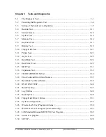
Page 115: ... CONFIDENTIAL Chapter 3 Tests and Diagnostics ...

Page 116: ...3 Tests and Diagnostics 3 ii CONFIDENTIAL PORTÉGÉ M500 Maintenance Manual 960 559 3 ...

Page 117: ...2 3 Heatrun test program 3 8 3 3 Setting of the hardware configuration 3 9 3 4 Heatrun Test 3 11 3 5 Subtest Names 3 12 3 6 System Test 3 14 3 7 Memory Test 3 16 3 8 Keyboard Test 3 17 3 9 Display Test 3 18 3 10 Floppy Disk Test 3 21 3 11 Printer Test 3 23 3 12 Async Test 3 25 3 13 Hard Disk Test 3 26 3 14 Real Timer Test 3 29 3 15 NDP Test 3 31 3 16 Expansion Test 3 32 3 17 CD ROM DVD ROM Test 3 ...

Page 118: ... 3 52 3 25 System Configuration 3 56 3 25 1 Function Description 3 56 3 25 2 Operations 3 57 3 26 Wireless LAN Test Program Atheros 3 58 3 26 1 Setting the responder machine 3 59 3 26 2 Test procedure 3 60 3 26 3 Contents of the test and errors 3 61 3 27 Wireless LAN Test Program Intel made a b g 3 65 3 28 LAN Modem Bluetooth IEEE1394 Test Program 3 69 3 27 1 LAN test 3 69 3 27 2 Modem test 3 72 3...

Page 119: ... 92 Tables Table 3 1 Subtest names 3 12 Table 3 2 Error codes and error status names 3 35 Table 3 3 Hard disk controller status register contents 3 38 Table 3 4 Error register contents 3 39 Table 3 5 Error message 3 75 Table 3 6 Error code for Bluetooth test BD_ADDR 3 76 Table 3 7 Error code for Bluetooth test BD_ADDR of the DUT 3 80 Table 3 8 Common error code 3 82 ...

Page 120: ...3 Tests and Diagnostics 3 vi CONFIDENTIAL PORTÉGÉ M500 Maintenance Manual 960 559 ...

Page 121: ...ent information of the computer It is also included in one of Diagnostic Disks The heatrun test is automatic test program which executes the some tests successively NOTE Before starting the diagnostics be sure to follow these steps 1 Check all cables are connected firmly 2 Exit any application and close Windows 3 Check if All Devices is selected in the Device Config in SETUP menu 3 1 1 Diagnostics...

Page 122: ...est module USB test A USB cable USB test An external CRT monitor Expansion test A CD test media TOSHIBA CD ROM TEST DISK or ABEX TEST CD ROM Sound test A DVD test media DVD ROM TEST DISK TSD 1 Sound test A music CD Sound test A store bought CD RW media CD ROM DVD ROM test A microphone Sound test Headphones Sound test A cleaning kit to clean the floppy disk drive heads Head Cleaning An exclusive mo...

Page 123: ...ollowing programs Initial configuration DMI information save DMI information recovery System configuration display E2PROM test MAC GUID DMI You will need the following equipment to perform some of the programs The Diagnostics Disk Main T D 3 1 3 Heatrun test program The heatrun test starts automatically after the selection You will need the following equipment to perform this program The Diagnosti...

Page 124: ...H Heatrun Enter a choice M To start the Diagnostics menu T D press M or m and Enter To start the H W initial information setting tool press I or i and Enter To start the Heatrun test press H or h and Enter NOTE When replacing the system board it is necessary to execute the followings 1 Before replacing save the DMI information by executing subtest 03 DMI information save in 3 3 Setting of the hard...

Page 125: ... c copyright TOSHIBA Corp 20XX DIAGNOSTICS MENU 1 DIAGNOSTIC TEST 2 ONLY ONE TEST 3 4 HEAD CLEANING 5 LOG UTILITIES 6 RUNNING TEST 7 FDD UTILITIES 8 SYSTEM CONFIGURATION 9 POWER OFF NOTE To exit the DIAGNOSTIC TEST MENU press the Esc key If a test program is in progress press Ctrl Break to exit the test program If a test program is in progress press Ctrl C to stop the test program PORTÉGÉ M500 Mai...

Page 126: ... 5 FLOPPY DISK TEST 6 PRINTER TEST 7 ASYNC TEST 8 HARD DISK TEST 9 REAL TIMER TEST 10 NDP TEST 11 EXPANSION TEST 12 CD ROM DVD ROM TEST 88 ERROR RETRY COUNT SET FDD HDD 99 EXIT TO DIAGNOSTICS MENU Functions 1 through 12 are the Diagnostic Tests Function 88 sets the floppy disk drive and hard disk drive error retry count 0 255 To exit the submenu of the Diagnostic Test and returns to the Diagnostic...

Page 127: ...ayed by your computer may be slightly different from the one shown above Select the desired subtest number from the subtest menu and press Enter The following message will appear TEST LOOP YES or NO ERROR STOP YES or NO Use the right and left arrow keys to move the cursor to the desired option Selecting YES of TEST LOOP increases the pass counter by one each time the test cycle ends and restarts t...

Page 128: ...error counter Table 3 1 in section 3 5 describes the function of each test on the subtest Table 3 2 in section 3 18 describes the error codes and error status names for each error Details of tests in DIAGNOSTIC TEST MENU are described on and after section 3 6 As for other service programs refer to section 3 20 to 3 25 3 2 2 H W initial information setting tool After selecting this test the followi...

Page 129: ...micro code Setting of the EHSS Inputting and writing of DMI information When the DMI information is displayed the following messages appear in order Input each information If you do not replace the PCB the DMI information should not be changed 1 Enter Model Name is displayed Input the computer s model name and press Enter e g DynaBook 2 Enter Version Number is displayed Input the computer s versio...

Page 130: ...DMI information recovery This is one of tools to copy the DMI information to a new PCB after replacing This subtest writes all the DMI data in the floppy disk into the new PCB NOTE Since the data of UUID is updated every time when this subtest DMI information recovery is done the saved UUID data is not written Subtest 08 System configuration display This subtest displays the information of the sys...

Page 131: ...t are executed successively For more details on the procedure and test content refer to Running Test When the heatrun test ends normally following message appears in the display HEATRUN NORMAL END Press any key to continue Press any key and return to the startup menu NOTE The test result Errorlog txt is stored in the floppy disk The result is displayed in the same format as Log Utilities For more ...

Page 132: ... Fan ON OFF Geyserville Quick charge DMI read 2 MEMORY 01 02 03 04 05 Conventional memory Protected Mode Protected Mode cache off Cache memory on off Stress 3 KEYBOARD 01 Pressed key code display 4 DISPLAY 01 02 03 04 05 06 07 VRAM read write for VGA Gradation for VGA Gradation for LCD Gradation Mode test for VGA All dot on off for LCD H pattern display LCD Brightness 5 FLOPPY DISK 01 02 03 04 05 ...

Page 133: ...oint to point receive Wraparound board 8 HARD DISK 01 02 03 04 05 06 07 08 09 Sequential read Address uniqueness Random address data Cross talk peak shift Partial Read Write specified address Read specified address Sequential write W R C specified address 9 REAL TIMER 01 02 03 Real time Backup memory Real time carry 10 NDP 01 NDP 11 EXPANSION 01 02 PCMCIA wraparound Not supported RGB monitor ID 12...

Page 134: ...0 FAN 1 2 To check the CPU fan press 1 and Enter To check the GPU fan press 2 and Enter To check both CPU fan and GPU fan press 0 and Enter The following message will appear Test Fan Revolution 0000RPM start Make sure the fan does not rotate then press Enter The following message will appear Test Fan Revolution Low speed Start Make sure the fan rotates at low speed then press Enter The following m...

Page 135: ...k charge Subtest 05 DMI read This subtest displays the information in the Flash ROM in the following format DMI Data Display Ver X XX Model Name XXXXXXXXXXX Version Number XXXXXXXXXXXX Serial Number XXXXXXXX Model Number XXXXXX XXXXX UUID Number XXXXXXXXXXXXXXXXXXXXXXXXXXXXXXXX Press Enter to EXIT To exit this subtest and return to the SYSTEM test menu press Enter ...

Page 136: ... data from 1MB to maximum MB and reads the new data and compares the result with the original data Subtest 03 Protected Mode cache off This subtest executes the same way as the subtest 02 with the cache off Subtest 04 Cache memory on off To test the cache memory a pass through write read comparison of 5Ah data is run repeatedly to the test area 7000 Program size to 7000 7FFF 32 KB to check the hit...

Page 137: ...btest 01 Pressed key code display When a key is pressed the scan code character code and key top name are displayed on the screen in the format shown below The Ins Lock Caps Lock Num Lock Scroll Lock Alt Ctrl Left Shift and Right Shift keys are displayed in reverse screen mode when pressed The scan codes character codes and key top names are shown in Appendix E KEYBOARD TEST IN PROGRESS 302000 Sca...

Page 138: ...02 Gradation for VGA This subtest displays four colors red green blue and white from left to right across the screen from black to maximum brightness The display below appears on the screen when this subtest is executed To exit this subtest and return to the DISPLAY TEST menu press Enter Subtest 03 Gradation for LCD This subtest displays bands of gradations for mixed colors then for red green and ...

Page 139: ...4 768 64K Mode 118 1024 768 16M The display below appears on the screen when this subtest is executed Display example Mode 12 To exit this subtest and return to the DISPLAY TEST menu press Enter after displaying the Mode 118 Subtest 05 All dot on off for LCD This subtest displays an all white screen then an all black screen The display changes automatically every three seconds and the screen retur...

Page 140: ...HHHHHHHHHHHHHHHHHHHHHHH HHHHHHHHHHHHHHHHHHHHHHHHHHHHHHHHHHHHHHHHHHHHHHHHHH HHHHHHHHHHHHHHHHHHHHHHHHHHHHHHHHHHHHHHHHHHHHHHHHHH HHHHHHHHHHHHHHHHHHHHHHHHHHHHHHHHHHHHHHHHHHHHHHHHHH HHHHHHHHHHHHHHHHHHHHHHHHHHHHHHHHHHHHHHHHHHHHHHHHHH HHHHHHHHHHHHHHHHHHHHHHHHHHHHHHHHHHHHHHHHHHHHHHHHHH HHHHHHHHHHHHHHHHHHHHHHHHHHHHHHHHHHHHHHHHHHHHHHHHHH HHHHHHHHHHHHHHHHHHHHHHHHHHHHHHHHHHHHHHHHHHHHHHHHHH To exit this subtes...

Page 141: ...t the media mode and start track to be tested and press Enter Test start track Enter 0 dd 00 79 2 The Floppy Disk test contains five subtests that test the FDD The floppy disk test menu will appear after you select FDD test parameters FLOPPY DISK XXXXXXX XXX DIAGNOSTIC TEST VX XX Ctrl Break test end Ctrl C key stop SUB TEST XX PASS COUNT XXXXX ERROR COUNT XXXXX WRITE DATA XX READ DATA XX ADDRESS X...

Page 142: ...t 04 only Track No Head No Subtest 01 Sequential read This subtest performs a Cyclic Redundancy Check CRC that continuously reads all the tracks track 0 to 39 0 to 79 on a floppy disk Subtest 02 Sequential read write This subtest continuously writes data pattern B5ADADh to all the tracks track 0 to 39 0 to 79 on a floppy disk The data is then read and compared to the original data Subtest 03 Rando...

Page 143: ...lowing message will appear after selecting the subtest 01 to 03 of the printer test channel 1 XXXXh channel 2 XXXXh channel 3 XXXXh Select the channel number 1 3 The printer I O port address is specified by the XXXXh number The computer supports three printer channels Select the printer channel number and press Enter to execute the selected subtest Subtest 01 Ripple pattern This subtest prints cha...

Page 144: ...t This subtest prints the various print types shown below Subtest 03 Wraparound NOTE To execute this subtest a printer wraparound connector must be connected to the computer s printer port This subtest checks the output and bi directional modes of the data control and status lines through the parallel port wraparound connector 34M741986G01 Both output and bi directional modes are tested 3 24 CONFI...

Page 145: ... 7Eh Subtest 01 FIR SIR point to point send NOTE To execute subtests 01 and 02 each computer must have access to the other computer s infrared port This subtest sends 20h through 7Eh data to the receive side then receives the sent data and compares it to the original data through the FIR SIR port Subtest 02 FIR SIR point to point receive This subtest is used with subtest 01 described above This su...

Page 146: ...reate back up disks as described below Check to see if the Microsoft Create System Disks Tools MSCSD EXE still exists in the System Tools Folder This tool can be used only once If it exists use it to back up the pre installed software then use the Backup utility in the System Tools folder to back up the entire disk including the user s files Refer to the operating system instructions 1 The followi...

Page 147: ...r The first digit of the STATUS indicates the drive being tested and the last two digits indicate the error status code as explained in the table 3 2 of the section 3 18 Subtest 01 Sequential read This subtest is a sequential reading of all the tracks on the HDD starting at track 0 When all the tracks on the HDD have been read the test starts at the maximum track and reads the tracks on the HDD se...

Page 148: ...inder 2DB6DB 6 cylinder D24974 7 cylinder Subtest 05 Partial Read This subtest reads 1GB data which is in minimum middle and maximum address of the HDD area Subtest 06 Write specified address This subtest writes specified data to a specified cylinder and head on the HDD Subtest 07 Read specified address This subtest reads data which has been written to a specified cylinder and head on the HDD Subt...

Page 149: ... new date PRESS ENTER KEY TO EXIT TEST 2 If the current date is not correct input the correct date at the Enter new date prompt and press Enter 3 The following messages will appear Current date XX XX XXXX Current time XX XX XX Enter new time PRESS ENTER KEY TO EXIT TEST 4 If the current time is not correct input the correct time in 24 hour format To enter press Shift The time is updated To exit th...

Page 150: ...nt date and time are erased This subtest checks the real time clock increments making sure the date and time are displayed in the following format Current date 12 31 1999 Current time 23 59 58 The real time increments are automatically executed and the following is displayed Current date 01 01 2000 Current time 00 00 00 PRESS Enter KEY TO EXIT TEST To exit the test press Enter ...

Page 151: ...960 559 CONFIDENTIAL 3 31 3 15 NDP Test To execute the NDP test select 10 from the DIAGNOSTICS TEST MENU press Enter and follow the directions on the screen Subtest 01 NDP This test checks the following functions of NDP Control word Status word Bus Addition Multiplication ...

Page 152: ...d connector is required This subtest checks the following signal line of the PC card slot Address line REG CE 1 CE 2 line Data line Speaker line Wait line BSY BVD1 line This subtest is executed in the following order Sub Address Good Bad Contents 01 00001 00001 nn nn xx xx Address line REG CE 1 CE 2 nn A0 90 80 00 02 00002 ww rr Data line ww write data rr read data 03 00003 Speaker line 04 00004 4...

Page 153: ... monitor with monitor ID function is required Connect the external monitor to the PC for the test of ID acquisition The judgment of acquisition is based on the panel data In simultaneous display mode or internal display mode in which the panel data is acquired this subtest will fail Therefore make sure only the external display is selected when executing this subtest ...

Page 154: ... or ABEX TEST CD ROM TCDR 702 and DVD ROM TEST DISK TSD 1 For the subtest 04 use a CD RW on the market Subtest 01 Sequential read This subtest is a sequential reading of one block units 2K bytes of all the logical addresses Subtest 02 Read specified address This subtest reads one block data from a specified address Subtest 03 Random address data This subtest reads one block data and multi block da...

Page 155: ...AC ADAPT ROM SENSING ERROR 1st Batt ROM SENSING ERROR 2nd Batt ROM THORMISTOR ERROR 1 ROM THORMISTOR ERROR 2 ROM THORMISTOR ERROR 3 Memory 01 02 DD RAM PARITY ERROR RAM PROTECTED MODE NO CHANGE RAM CACHE MEMORY ERROR Keyboard FE FD F0 F1 F2 F3 F4 F5 F6 F7 F8 F9 FA EF ED USB GET DESCR ERROR FIRST USB SET ADDRESS ERROR HUB GET DESCR ERROR Top 8B HUB GET DESCR ERROR Whole HUB SET CONFIGURATION ERROR ...

Page 156: ...0 PRT TIME OUT PRT FAULT PRT SELECT LINE PRT OUT OF PAPER PRT POWER OFF PRT BUSY LINE ASYNC 01 02 04 08 10 20 40 80 88 05 06 RS232C DTR ON TIME OUT RS232C CTS ON TIME OUT RS232C RX READY TIME OUT RS232C TX FULL TIME OUT RS232C PARITY ERROR RS232C FRAMING ERROR RS232C OVERRUN ERROR RS232C LINE STATUS ERROR RS232C MODEM STATUS ERROR SIR TIME OUT ERROR FIR TIME OUT ERROR HDD 05 07 09 0B BB 08 01 02 0...

Page 157: ... PROCESSOR NDP CONTROL WORD ERROR NDP STATUS WORD ERROR NDP BUS ERROR NDP ADDITION ERROR NDP MULTIPLAY ERROR EXPANSION C1 C3 C4 C5 C6 C7 C8 CB CC CE CF ADDRESS LINE ERROR CE 1 LINE ERROR CE 2 LINE ERROR DATA LINE ERROR WAIT LINE ERROR BSY LINE ERROR BVD1 LINE ERROR ZV Port ERROR NO PCMCIA CARD TYPE ERROR ZV_CONT ERROR CD ROM DVD ROM 01 02 03 04 05 06 09 11 20 40 80 90 B0 BAD COMMAND ILLEGAL LENGTH...

Page 158: ...e displays the HDC error register The contents of the HDC status register and error register are listed in Tables 3 3 and 3 4 Table 3 3 Hard disk controller status register contents Bit Name Description 7 BSY Busy 0 HDC is ready 1 HDC is busy 6 DRY Drive ready 0 Hard disk drive is not ready to accept any command 1 Hard disk drive is ready 5 DWF Drive write fault 0 DWF error is not detected 1 Write...

Page 159: ...etected 6 UNC Uncorrectable 0 There is no uncorrectable data error 1 Uncorrectable data error has been detected 5 Not used 4 IDN Identification 0 Not used 1 There is no ID field in the requested sector 3 Not used 2 ABT Abort 0 Not used 1 Illegal command error or command abort 1 TK0 Track 0 0 The hard disk found track 0 during a recalibrate command 1 The hard disk could not find track 0 during a re...

Page 160: ...erations Select test 2 from the DIAGNOSTIC MENU and press Enter The following menu appears in the display ONLY ONE TEST Menu XXXXXXXXX 1 Pressed Key Display 2 Touch Pad 3 GP Button 4 Wireless communication switch 5 USB 6 LED A Acceleration sensor 9 Exit to Common Test Press test number 1 A Select the subtest number you want to test and press Enter To return to the DIAGNOSTIC TEST menu select 9 and...

Page 161: ...awn on the display as shown below When any key is pressed the corresponding key on the screen changes to the key character that was pressed Holding a key down enables the auto repeat function that causes the key s display character to blink Press Del Enter to end the test PORTÉGÉ M500 Maintenance Manual 960 559 CONFIDENTIAL 3 41 ...

Page 162: ...ch When moving your finger on the touch pad towards the upper left the POINTING display changes according to the following illustration If a touch pad switch is pressed the BUTTONS displays appear on the right side one by one The parameters appear above the BUTTONS 1 or 2 corresponding to the pressed touch pad switch highlights To end this subtest press two touch pad switches at the same time 3 42...

Page 163: ...ton is pressed the following message appears Press Fforward button If the correct button is pressed the display returns to the ONLY ONE TEST menu Subtest 04 Wireless communication switch This subtest checks if the Wireless communication switch works properly If the test is started with the switch ON following message appears in the display Wireless communication switch is set to a start position O...

Page 164: ... in the display if an error is found during the test Confirm the connection of cable and then execute the test again Press 9 and Enter to return to ONLY ONE TEST menu Subtest 06 LED This subtest checks if each LED lights properly The following message appears in the display in order Follow the instructions in the display to execute the test HDD Access LED test Press any key and following message a...

Page 165: ...ollowing condition 1 Flat desk with vertical plane to get the stability of machine 2 The vertical wall or plane is necessary 3 Prevent the machine from shake or shock Vertical plane Flat desk Set the machine against the vertical plane with the Front upward Example The figure below shows the name and position of each side PORTÉGÉ M500 Maintenance Manual 960 559 CONFIDENTIAL 3 45 Right side Left sid...

Page 166: ...lane on the flat desk with the right side of machine upward Then press Enter to detect the data on this setting of machine The following message appears in the display The front establishes in the upper direction Press Enter key Set the machine against the vertical plane on the flat desk with the front of machine upward Then press Enter to detect the data on this setting of machine The following m...

Page 167: ...rform this program 3 21 2 Operations 1 Selecting test 4 from the DIAGNOSTIC MENU and pressing Enter displays the following messages DIAGNOSTICS FLOPPY DISK HEAD CLEANING VX XX Mount cleaning disk s on drive s Press any key when ready 2 Remove the Diagnostics Disk from the FDD then insert the cleaning disk and press Enter 3 When the cleaning start message appears the FDD head cleaning has begun 4 T...

Page 168: ...esults in RAM This function can store data on a floppy disk or output the data to a printer or the display The error information is displayed in the following order 1 Error count CNT 2 Test name Subtest number TS No 3 Pass count PASS 4 Error status STS 5 FDD HDD or memory address ADDR 6 Write data WD 7 Read data RD 8 HDC status HSTS 9 Error status name ERROR STATUS NAME If the power switch is turn...

Page 169: ... Clear 5 Print 6 FD Log Read 7 FD Log Write 2 The error information displayed on the screen can be manipulated by the following number keys The 1 key scrolls the display to the next page The 2 key scrolls the display to the previous page The 3 key returns to the Diagnostic Menu The 4 key erases all error log information in RAM The 5 key outputs the error log information to a printer The 6 key read...

Page 170: ...pull out the test program and insert a floppy disk which has been formatted by FORMAT command of DOS 1 Pull out the test program and insert a floppy disk which has been formatted by FORMAT command of DOS 2 Select 6 from the DIAGNOSTIC MENU and press Enter the following messages for selectable tests will appear in the display in order FDD write read test Y N Printer wrap around test Y N Serial wrap...

Page 171: ... the Toshiba MS DOS FORMAT command This program can format a floppy disk in the following formats a 2DD Double sided double density double track 96 135 TPI MFM mode 512 bytes 9 sectors track b 2HD Double sided high density double track 96 135 TPI MFM mode 512 bytes 18 sectors track 2 COPY This program copies data from a source floppy disk to a target floppy disk 3 DUMP This program displays the co...

Page 172: ...ing message Type select 0 2DD 3 2HD c Select a media drive type number and press Enter A message similar to the one below will be displayed Warning Disk data will be destroyed Insert work disk into drive A Press any key when ready d Remove the Diagnostics Disk from the FDD insert the work disk and press any key The following message will be displayed when the FDD format is executed FDD TYPE TRACK ...

Page 173: ... has started FDD TYPE TRACK XXX FDD TYPE HEAD X FDD TYPE SECTOR XX Copy start track head XXX X d The following message will appear Insert target disk into drive A Press any key when ready e Remove the source disk from the FDD then insert a formatted work disk and press any key The following message will appear and start copying to the target disk track head XXX X f When the amount of data is too l...

Page 174: ...ng message will appear Select a media mode 2HD media mode 1 1 20MB 2 1 44MB 3 1 23MB e The following message will appear Insert source disk into drive A Press any key when ready f Insert a source disk and press any key and the following message will appear Max address Track XXXX Head XX Sector XX Track number g Set the track number head number and sector number you want to dump The system will acc...

Page 175: ...pear To finish the dump select 3 Press number key 1 up 2 down 3 end l The following message will appear Selecting 2 returns to the FDD UTILITIES MENU Another dump 1 Yes 2 No 5 HDD ID READ program Selecting HDD ID displays the following HDD ID configuration HDD ID Read VX XX Drive 1 Model No XXXXXXX Press Enter to return to the FDD UTILITIES MENU ...

Page 176: ...ired The System Configuration program contains the following configuration information for the computer 1 Processor Type Code L2 cache 2 Chip set VRAM 3 BIOS ROM version 1st ID 2nd ID 4 Boot ROM version 5 EC total version 6 PS Microprocessor version 7 Micro code revision Processor number 8 Total Memory Size Conventional memory 9 Battery code 10 HWSC 11 FSB Voltage 12 The number of printer ports 13...

Page 177: ...D XXH BOOT ROM Version VX XX EC Total Version VX XX PS Micon Version VX XX Micro code Revision VX XX Processor XXXh Total Memory Size XXXXXXMB Conventional Memory XXXKB Battery Code XXXXXXXXXXXX HWSC XXXXXXX FSB XXXXXMHz Voltage XEh X Printer Adapter LPT1 XXXX LPT2 XXXX LPT3 XXXX X ASYNC Adapter COM1 XXXX COM2 XXXX COM3 XXXX X Math CO Processor X USB Floppy Disk Drive s Track XX Head XX Sector XX ...

Page 178: ...a responder machine to perform this test The computer must be booted by the Responder T D In this test the following items are tested 1 SKU check of Module 2 MAC Address Check 3 Communication test of 11a mode 4 Communication test of 11b mode 5 Communication test of 11g mode 6 SKU MAC Check 11a b g communication test NOTE This test take time until it completes To start the Wireless LAN test program...

Page 179: ...heros MB5x Responder mode Please exchange FD for MB5x Responder media m Atheros MB6x setup mode Please input the s h r m key and push the Enter key 3 The RAM drive name which has been set at booting is displayed and command input is requested Input mb6x X and press Enter The part of X is the RAM drive name In the following display it is C 1 440 1K C Installed Device RAMDRIVE Please input the follo...

Page 180: ... MB5x MB6x Maintenance T D Menu s Atheros MB4x DUT mode Please exchange FD for MB4x DUT media h Atheros MB5x DUT mode Please exchange FD for MB5x DUT media r Atheros MB5x Responder mode Please exchange FD for MB5x Responder media m Atheros MB6x setup mode Please input the s h r m key and push the Enter key 3 The following message is displayed Change the FD with MB6x setup media 1 and press Enter T...

Page 181: ... Module 2 MAC Address Check 3 Communication test of 11a mode 4 Communication test of 11a mode Main Antenna Only 5 Communication test of 11b mode 6 Communication test of 11b mode Main Antenna Only 7 Communication test of 11g mode 8 Communication test of 11g mode Main Antenna Only 9 All the tests of module SKU MAC Check 11a b g communication test A All the tests of module Main Antenna Only SKU MAC C...

Page 182: ...dress of the installed Wireless LAN card is checked If it is not incorrect MAC address the following is displayed MAC Address Check OK a Case of All FF error Mac Address Check NG FFFFFF FFFFFFh b Case of All 00 error Mac Address Check NG 000000 000000h 3 Communication test of 11a mode The check of connection of 11a mode antenna and transmitting receiving test are executed When the test has been fi...

Page 183: ...st are executed When the test has been finished normally the following is displayed 11b Communication Test OK When an error has detected the following is displayed 11b Communication Test NG Please refer to log txt 5 Communication test of 11g mode The check of connection of 11g mode antenna and transmitting receiving test are executed When the test has been finished normally the following is displa...

Page 184: ...960 559 6 SKU MAC Check 11a b g communication test All the test is executed in the order of SKU check of Module MAC Address Check Communication test of 11a mode Communication test of 11b mode and Communication test of 11g mode The check of connection of 11g mode antenna and transmitting receiving test are executed ...

Page 185: ...ower while pressing U The following menu appears in the display Intel PRO Wireless 3945ABG Network Connection Maintenance T D Menu 1 SKU check of Module 2 MAC Address Check 3 Antenna Check communication test of 11b mode 4 Communication test of 11a mode 5 Communication test of 11g mode 6 All the tests of 11a g Card SKU MAC Check 11a b g communication test SELECT TEST No 1 6 To execute the subtest i...

Page 186: ...e connection execute the subtest again Subtest02 MAC Address Check This subtest displays the MAC address Selecting this subtest following message will appear in the display MAC XXXXXXXXXXXX MAC Address Check OK Press any key and return to the test menu If a defective is found during the test following message will appear in the display ERROR MAC all F MAC XXXXXXXXXXXX MAC Address Check NG Press an...

Page 187: ... any key the following message which antenna is defective is displayed Main Antenna Test NG Aux Antenna Test NG Press any key and return to the test menu Subtest04 Communication test of 11a mode This subtest execute transmitting receiving test in 802 11a mode using the main antenna If a defective is not found during the test OK message will appear in the display Press any key and return to the tes...

Page 188: ...the test NG message will appear in the display When pressing any key the following message is displayed 11g Communication Test NG When a defective is detected in the test following typical cause is considered Connection of wireless LAN card Defective wireless LAN card Disappearance of MAC address data Checking the connection execute the subtest again Subtest06 All the tests of 11a b g Card All the...

Page 189: ... on the power The following message will appear Microsoft Windows XX Startup Menu 1 LAN 2 Modem 3 Bluetooth 4 IEEE1394 Enter a choice Press the number you want to test and press Enter NOTE It is impossible to go back to startup menu once you choose the test Therefore LAN Modem Bluetooth IEEE1394 test can not be executed successively 3 28 1 LAN test To execute LAN test press 1 and Enter The followi...

Page 190: ...t receive test COMPLETED Repeat count 00000 Error count 00000 LOOPBACK TEST 100Mbps Auto negotiation TxRx Test Destination Address xxxxxxxxxxxx Source Address xxxxxxxxxxxx 100Base TX Full Duplex TRANSMIT RECEIVE NOTE The menu displayed by your computer may be slightly different from the one shown above If a defective is found NG message will appear in the display 3 70 CONFIDENTIAL PORTÉGÉ M500 Mai...

Page 191: ...r The following message will appear Testing adaptor hit ESC to abort External Loopback Test PASSED Testing completed Loopback Test Complete 1000Base Auto negotiation TxRx Test CE Test Complete NOTE The menu displayed by your computer may be slightly different from the one shown above If a defective is found NG message will appear in the display PORTÉGÉ M500 Maintenance Manual 960 559 CONFIDENTIAL ...

Page 192: ...te Modem test press 2 and Enter Following message will appear Modem loopback test ICHx MDC Test Program with Modem Sound Line Test Version X X Scorpio Modem Initialize OK Digital Loopback Test OK RJ11 Connector Check LED Operator s Check NOTE The menu displayed by your computer may be slightly different from the one shown above RJ11 Connection Check LED Operator s Check LED test will be executed a...

Page 193: ...to perform this test Insert a floppy disk containing the test program into the target machine and turn on the target machine The following Bluetooth test menu will appear Bluetooth sub system test program VX XX 1 BD_ADDR check 3 Communications test DUT mode T communications test TEST mode Press test number 1 3 T Press 1 or 3 key to perform the corresponding subtest To quit the Bluetooth test progr...

Page 194: ...press Enter The following message will appear Bluetooth Subsystem T D for PCSE BD_ADDR VerX XX Copyright C by TOSHIBA Co Initializing When the machine has passed the test it displays BD_ADDR If BD_ADDR has no problem the following message is displayed Bluetooth Subsystem T D for PCSE BD_ADDR VerX XX Copyright C by TOSHIBA Co My BD_ADDR XXXXXXXXXXXX h PPPPPP A SSSSS SSSSS P P A A S S S S P P A A S ...

Page 195: ... Bluetooth Subsystem T D for PCSE BD_ADDR VerX XX Copyright C by TOSHIBA Co My BD_ADDR XXXXXXXXXXXX h FFFFFF A III L F A A I L F A A I L FFFFFF A A I L F AAAAAAA I L F A A I L F A A III LLLLLLL Table 3 5 Error message Message Contents Invalid BD_ADDR all 00 0x000000000000 Invalid BD_ADDR all FF 0xFFFFFFFFFFFF Invalid BD_ADDR bit0 1 bit40 1b Invalid BD_ADDR bit1 1 bit41 1b Invalid BD_ADDR define in...

Page 196: ... ACL Connection already exists 0x0c Command Disallowed 0x0d Host Rejected due to limited resources 0x0e Host Rejected due to security reasons 0x0f Host Rejected due to remote device is only a personal device 0x10 Host Timeout 0x11 Unsupported Feature or Parameter Value 0x12 Invalid HCI Command Parameters 0x13 Other End Terminated Connection Used Ended Connection 0x14 Other End Terminated Connectio...

Page 197: ...pecification of the Bluetooth System in detail Subtest03 Communication tests DUT mode This subtest checks the Bluetooth communication functions Preparing the tester machine for the Bluetooth test program Insert a floppy disk containing the test program into the tester machine and turn on the tester machine The Bluetooth test menu will appear Press 3 to select the test and press Enter in the target...

Page 198: ... Space to start the Bluetooth communication test When the machine has passed the test it displays BD_ADDR of the DUT If the connection with the tester is completed the progress bar stops The following message is shown Bluetooth Subsystem T D for PCSE CS Air VerX XX Copyright C by TOSHIBA Co DUT BD_ADDR of the DUT XXXXXXXXXXXXX h CCCC OOO M M PPPPPP L EEEEEE TTTTTTT EEEEEEE DDDDD C C O O MM MM P P ...

Page 199: ...e Bluetooth Subsystem T D for PCSE CS Air VerX XX Copyright C by TOSHIBA Co DUT BD_ADDR of the DUT XXXXXXXXXXXXX h III N N CCCC OOO M M PPPPPP L EEEEEE TTTTTTT EEEEEEE I NN N C C O O MM MM P P L E T E I N N N C O O M M M M P P L E T E I N N N C O O M M M PPPPPP L EEEEEE T EEEEEEE I N N N C O O M M P L E T E I N NN C C O O M M P L E T E III N N CCCC OOO M M P LLLLLLL EEEEEE T EEEEEEE Testing is fin...

Page 200: ...e 0x0b ACL Connection already exists 0x0c Command Disallowed 0x0d Host Rejected due to limited resources 0x0e Host Rejected due to security reasons 0x0f Host Rejected due to remote device is only a personal device 0x10 Host Timeout 0x11 Unsupported Feature or Parameter Value 0x12 Invalid HCI Command Parameters 0x13 Other End Terminated Connection Used Ended Connection 0x14 Other End Terminated Con...

Page 201: ...Error code Meaning 0x20 Unsupported LMP Parameter Value 0x21 Role Change Not Allowed 0x22 LMP Response Timeout 0x23 LMP Error Transaction Collision 0x24 LMP PDU Not Allowed 0x25 Not Exist 0x26 Not Exist 0x27 Not Exist 0x28 Not Exist 0x29 Not Exist 0x2a Not Exist 0x2b Not Exist 0x2c Not Exist 0x2d Not Exist 0x2e Not Exist 0x2f Not Exist See the Specification of the Bluetooth System in detail ...

Page 202: ...is OFF 0x3a Module dose not exist 0x3b Module exists not error 0x3c Command Line is wrong 0x3d Side band access driver is not resident 0x3e Bluetooth driver for DOS is not resident 0x3f Get Status function of Side band access driver is not normal 0x40 No reply to inquiry 0x41 Device Descriptor can not be acquired USB I F is not normal 0x42 Sideband reset timeout occurs 0x43 Descriptor type is wron...

Page 203: ...ss test number 1 3 To execute the TEST select the test number you want to execute and press Enter Subtest01 Transmit Receive test NOTE Before executing subtest 01 be sure to execute subtest 02 in the responder machine This program checks the data transporting between responder machine and target machine and compare them with the original data through the IEEE1394 cable Subtest 02 Responder set Thi...

Page 204: ...gram is stored to the HDD Reboot the computer from the HDD The following message will appear WSS Sound blaster pro Diagnostics program 1 Sound Standard 2 Sound Legacy 3 CD Sound Standard 4 CD Sound Legacy It outputs at the speaker and lineout Press test number 1 4 Input the test number and press Enter 3 29 1 Sound Standard test To execute the Sound Standard test press 1 and Enter The following men...

Page 205: ...rter When this subtest is selected the following message will appear Recording play test And the following message will appear DOS 4GW Protected Mode Run time Version X XX Copyright c Tenberry Software Inc XXXX After this message appears display stops briefly In this timing sound is recorded from internal microphone After the recording is completed the computer plays back the sound recorded after ...

Page 206: ... the data can be measured as a sine wave When the subtest is executed the sine wave is played while expanding sine wave from 16KB to 64KB The display returns to the Sound Standard test menu after the test ends Subtest 03 Line IN recording play This subtest executes the same test as the subtest01 by recorded sound from the different port Line in port For more details on the subtest refer to the sub...

Page 207: ...o CD 3 29 3 1 Test media Toshiba made test media CD DVD TEST IN PROGRESS XXXXXXXX xxxxxxx DIAGNOSTIC TEST VX XX Ctrl Break test end Ctrl C key stop SUB TEST XX PASS COUNT XXXXX ERROR COUNT XXXXX WRITE DATA XX READ DATA XX ADDRESS XXXXXX STATUS XXX 01 Japanese Narration 02 English Narration 03 Test Tone A 100Hz 20Hz 04 Test Tone B 400Hz 3KHz L R Drive 0 ATAPI status 00 Command XX Block address XXXX...

Page 208: ...ing subtest03 be sure to set the sound at proper volume This subtest plays sine wave while changing its table from 100Hz to 20Hz The test returns to the CD Sound Standard menu after the test ends Subtest 04 Test Tone B This subtest plays sine wave while changing its table from 400Hz to 3KHz and also changing the channel from left speaker to right speaker The test returns to the CD Sound Standard m...

Page 209: ... address XXXXXXXX Block length XXXXXXXX Final Block address XXXXXXXXX Select the track number you want to test and press Enter twice The following message appears in the display and selected track is played Play start CD sound Press any key play stop After pressing any key the music stops and the display returns to the selection menu of the track number NOTE When the CD ROM test is executed ALL DE...

Page 210: ...M DD YYYY b Time HH MM SS 3 Battery a Battery Save Mode b PCI Express Link ASPM c Enhanced C States 4 Password 5 HDD Password a HDD b HDD Password Mode c User Password d Master Password 6 Boot Priority a Boot Priority b HDD Priority c Network Boot Protocol 7 Others a Core Multi Processing b Dynamic CPU Frequency Mode c Execute Disable Bit Capability d Virtualization Technology e Auto Power On f Be...

Page 211: ...rives I O a Built in HDD b CD ROM 10 PCI Bus a PCI Bus 11 Security Controller a TPM b Clear TPM Owner 12 Display a Power On Display b LCD Display Stretch 13 Peripheral a Internal Pointing Device 14 Legacy Emulation a USB KB Mouse Legacy Emulation b USB FDD Legacy Emulation c USB Memory BIOS Support Type 15 PCI LAN a Built in LAN ...

Page 212: ...ress F1 The following display appears NOTE 1 This appears in Intel CoreTM models 2 This appears in PORTÉGÉ M500 only PPM51 and TECRA M6 3 This appears in models that have 10 100M Ether Net LAN 4 This appears in models that have a CPU supporting TPM 5 This appears in models that have a CPU supporting this function 3 92 CONFIDENTIAL PORTÉGÉ M500 Maintenance Manual 960 559 ...

Page 213: ...item requires the system to reboot the following message is displayed Are you sure Y N The changes you made will cause the system to reboot 2 To make other changes press N Repeat the steps above 3 To accept the changes press Y NOTE You can press Esc to quit at any time without saving changes SETUP asks you to confirm that you do not want to save your changes When SETUP is displayed at the next tim...

Page 214: ... System Date Time Use this option to set the computer s system date time Press to move the cursor to the right and press to move the cursor to the left Press the space bar to increase the number and press BkSp to decrease the number a Date Use this option to set the system date of the computer b Time Use this option to set the system time of the computer 3 Battery This option is used to select Ful...

Page 215: ...Default Disabled Disables sleep mode LCD Brightness Use this option to set the level of LCD brightness Super Bright Full brightness for maximum visibility Bright Full brightness for high visibility Default Semi Bright Less than full brightness for saving power Cooling Method If the CPU becomes too hot the fan turns on or the processing speed is lowered automatically When the CPU temperature falls ...

Page 216: ...d This option allows you to set or reset the user password for power on Not Registered Change or remove the password Default For details on setting the user password refer to the User s Manual 5 HDD Password This option sets HDD password HDD password is a security function to protect the built in HDD a HDD This item selects the hard disk to set HDD password Built in HDD Sets HDD password for the b...

Page 217: ...ority HDD FDD CD ROM LAN The computer looks for bootable files in the following order HDD FDD CD ROM and LAN Default FDD HDD CD ROM LAN The computer looks for bootable files in the following order FDD HDD CD ROM and LAN HDD CD ROM LAN FDD The computer looks for bootable files in the following order HDD CD ROM LAN and FDD FDD CD ROM LAN HDD The computer looks for bootable files in the following ord...

Page 218: ...s you use a Core Multi Processing The Core Multi Processing sets the CPU operating mode of Core Multi Processor Enabled Enables Core Multi Processing functions Default Disabled Disables Core Multi Processing functions b Dynamic CPU Frequency Mode Use this option to choose a setting from the followings Dynamically Switchable Enables Intel SpeedStep technology When the computer is in use the CPU pow...

Page 219: ...arm Date Option appears only when Alarm Time is enabled Only for LAN Model Alarm Time is set in the sequence of hours and minutes Seconds cannot be changed Alarm Date Option is set in the sequence of month and day If Alarm Date is set to Disabled the computer will be powered on at the same time every day Press to move the cursor to the right and to move the cursor to the left when you set the date...

Page 220: ...s the language during bootup This message appears only on the model for TCL Canada English The message is displayed in English Default French The message is displayed in French 8 Configuration This option displays the configuration method a Device Config The devices are initialized when the PNP OS loads Setup by OS First devices necessary for loading the OS will be initialized After the PNP OS loa...

Page 221: ...oller a TPM Disables the security controller called TPM Trusted Platform Module When the cursor is on the Enable Disable and the Space is pressed message is displayed and the PC waits Y or N key input by the user When Y is pressed it is sets to Enable Disable After changing the cursor could not be moved on the TPM tem This option can be changed after rebooting Disabled Disables the TPM Default Ena...

Page 222: ...and the external monitor for simultaneous display NOTE Pressing Fn F5 changes the display setting in the order of internal LCD to simultaneous to external monitor b LCD Display Stretch LCD Display Stretch enables or disables a larger display area of the screen Enabled Enables the LCD display stretch feature Default Disabled Disables the LCD display stretch feature 13 Peripheral Use this option to ...

Page 223: ...r disable USB FDD Legacy Emulation Enabled USB Legacy Support can be used Default Disabled USB Legacy Support cannot be used c USB Memory BIOS Support Type Sets the type of the USB memory as a startup device HDD Set the type of the USB memory to be equivalent to the HDD Default Based on the HDD order in the Boot Priority Options item The order with respect to the other HDD can be set in the HDD Pr...

Page 224: ...3 Tests and Diagnostics 3 30 SETUP 3 104 CONFIDENTIAL PORTÉGÉ M500 Maintenance Manual 960 559 ...

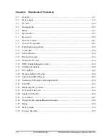
Page 225: ...Chapter 4 Replacement Procedures CONFIDENTIAL ...

Page 226: ...4 Replacement Procedures 4 ii CONFIDENTIAL PORTÉGÉ M500 Maintenance Manual 960 559 ...

Page 227: ...eless LAN card 4 36 4 15 MDC Modem Daughter Card 4 38 4 16 Internal microphone 4 40 4 17 RTC battery 4 42 4 18 Harness holder LAN cable 4 44 4 19 System board DC IN jack 4 47 4 20 Modem jack Wireless communication SW 4 50 4 21 Fan CPU 4 53 4 22 HDD cable PC card slot 4 57 4 23 LCD unit FL inverter 4 59 4 24 Speaker LCD cable 4 65 4 25 Cover latch 4 67 4 26 Wireless LAN antenna Bluetooth antenna 4 ...

Page 228: ...assembly 3 4 25 Figure 4 14 Removing the Cover FAT assembly 4 4 26 Figure 4 15 Removing the fingerprint sensor board 4 28 Figure 4 16 Removing the touch pad assembly 4 30 Figure 4 17 Removing the SW membrane 1 4 32 Figure 4 18 Removing the SW membrane 2 4 33 Figure 4 19 Removing the Bluetooth module 4 34 Figure 4 20 Removing the wireless LAN card 4 36 Figure 4 21 Removing the MDC Modem Daughter Ca...

Page 229: ...bly 4 59 Figure 4 39 Removing the LCD mask 4 60 Figure 4 40 Removing the FL inverter 4 61 Figure 4 41 Removing the LCD unit 4 62 Figure 4 42 Removing the LCD support 4 63 Figure 4 43 Removing the speaker 4 65 Figure 4 44 Removing the LCD cable 4 66 Figure 4 45 Removing the cover latch 4 67 Figure 4 46 Removing the wireless LAN antenna Bluetooth antenna 4 68 Figure 4 47 Removing the hinge 4 70 Figu...

Page 230: ...4 Replacement Procedures 4 vi CONFIDENTIAL PORTÉGÉ M500 Maintenance Manual 960 559 ...

Page 231: ...ext optional items such as the optional PC card and optional SD card then follow the line on the chart to determine which FRU you must remove next in order to repair the one you think is causing the computer to operate improperly Refer to the example at the bottom of the page How to see the chart This chart shows which unit s you need to remove in advance when you replace one unit Example When you...

Page 232: ...onnected from an AC power source Remove any metal jewelry or accessories such as necklaces bracelets or rings in order to reduce the risk of electric shock Never work with wet or damp hands 3 Be careful of edges and corners as these may cut CAUTION 1 When you change a component be sure the replacement component meets the required specifications Never use foreign parts to avoid any risk of damage t...

Page 233: ... the necessary diagnostics tests described in this manual 5 Do not perform any operations that are not necessary and use only the described procedures for disassembling and installing FRUs in the computer 6 After removing parts from the computer place them in a safe place away from the computer so they will not be damaged and will not interfere with your work 7 You will remove and replace many scr...

Page 234: ...n connectors are used with all other cables These connectors can be connected and disconnected by simply pulling them apart or pushing them together Assembly Procedures After you have disassembled the computer and fixed or repaired the problem that was causing the computer to operate abnormally you will need to reassemble the computer Install all the removed FRUs following the steps described in t...

Page 235: ... parts The following equipment is necessary to disassemble and reassemble the computer One M2 point size 0 Phillips screwdriver One M2 5 M3 point size 1 Phillips screwdriver One screw driver for stud screw One 4 mm flat blade screwdriver Tweezers to lift out screws that you cannot grasp with your fingers ESD mats for the floor and the table you are working on An ESD wrist strap or heel grounder An...

Page 236: ...sult in electrical shorts or other damage if screws or components come loose NOTE Toshiba recommends that you use an electric screw driver for quick and easy operations M2 0 167 N m 1 7 kgf cm M2 5 0 294 N m 3 0 kgf cm M3 0 549 N m 5 6 kgf cm NOTE The computer contains several flat head screws These screws have less contact area with the screwdriver so be careful to press firmly enough to prevent ...

Page 237: ...re decimal places such as 2 5 mm or 2 8 mm Marking of Screws on the Computer Body To make maintenance of the computer easier markings of the kinds of the screws including the types and lengths of the screws are indicated on the computer body Kind of screws Symbol BIND screw B FLAT HEAD screw F SUPER THIN HEAD screw S TAPPING screw T Other screws U Unique screws STUD etc Examples 6 mm BIND screw B6...

Page 238: ...eak twist or bend the battery pack 1 Turn off the power of the computer 2 Disconnect the AC adapter and other external devices from the computer 3 Turn the computer face down 4 Release the battery lock Pull out the battery pack while sliding the battery latch as shown in the following figure NOTE For environmental reasons do not throw away a spent battery pack Battery pack Battery latch Battery lo...

Page 239: ... used handled or disposed of For environmental reasons collect the spent battery packs Use only batteries recommended by Toshiba for replacements NOTE Check the battery s terminals visually If they are dirty wipe them clean with a dry cloth 1 Turn off the power of the computer 2 Disconnect the AC adapter and all other external devices to the computer 3 Push the battery pack into the battery slot M...

Page 240: ...d precautions 1 Press the eject button for the PC card you want to remove to extend the button 2 Press the extended eject button to pop the PC card out 3 Grasp the PC card and pull it out Eject button PC card Figure 4 2 Removing the PC card Installing the PC card To install the PC card follow the steps below and refer to Figure 4 2 1 Insert the PC card into the card slot 2 Push it carefully to ens...

Page 241: ...dures and precautions 1 Push the Bridge media in and release it to pop the card out 2 Grasp the Bridge media and pull it out For an instance SD card is described in the figure 4 3 Bridge media SD card Figure 4 3 Removing the Bridge media SD card Installing the Bridge media To install the Bridge media follow the steps below and refer to Figure 4 3 1 Insert the Bridge media in the card slot 2 Push i...

Page 242: ... and refer to Figure 4 4 and 4 5 1 Turn the computer upside down 2 Loosen the screw with an e ring and remove the HDD cover while releasing latches 3 Pull the tab of the HDD assembly to remove it from the connector of the HDD cable Be careful not to damage the connector HDD cover Screw e ring HDD assembly Tab Figure 4 4 Removing the HDD cover 4 12 CONFIDENTIAL PORTÉGÉ M500 Maintenance Manual 960 5...

Page 243: ...properly 4 Place the HDD assembly on a flat surface and remove the following screws M3 4S FLAT HEAD screw 4 5 Separate the HDD and HDD Holder CAUTION Do not apply pressure to the top or bottom of the HDD M3 4S FLAT HEAD HDD HDD Holder M3 4S FLAT HEAD Figure 4 5 Separating the HDD and HDD holder PORTÉGÉ M500 Maintenance Manual 960 559 CONFIDENTIAL 4 13 ...

Page 244: ...t may damage the HDD 1 Seat the HDD in the HDD Holder and secure them with the following screws M3 4S FLAT HEAD screw 4 CAUTION Do not apply pressure to the center of the HDD assembly It may damage the HDD assembly Hold the HDD assembly by its corners 2 Set the connector of the HDD cable upward and connect firmly the HDD assembly to the connector Lay the HDD assembly down in the slot 3 Set the HDD...

Page 245: ... It may cause injury 1 Remove the following two screws securing the slim select M2 5 4B FLAT HEAD screw 1 M2 5 16B FLAT HEAD screw 1 2 While sliding the hook in the direction of the arrow in the figure below remove the optical drive from connector on the system board M2 5 4B FLAT HEAD Optical drive M2 5 16B FLAT HEAD Hook Figure 4 6 Removing the optical drive PORTÉGÉ M500 Maintenance Manual 960 55...

Page 246: ...d the pushing plate M2 3S S THIN HEAD screw 2 4 Remove the following screws and the mounting plate M2 3B BIND screw 1 M2 3B BIND Mounting plate M2 3S S THIN HEAD Pushing plate Figure 4 7 Disassembling the optical drive 4 16 CONFIDENTIAL PORTÉGÉ M500 Maintenance Manual 960 559 ...

Page 247: ...d secure it with the following screws M2 3S S THIN HEAD screw 2 3 Insert the optical drive firmly into the computer to connect it to the connector on the system board 4 Secure the optical drive with the following screws M2 5 4B FLAT HEAD screw 1 M2 5 16B FLAT HEAD screw 1 CAUTION When inserting the slim select bay module turn the computer face up and insert it while slightly pressing it down Optic...

Page 248: ...over the computer and open the display 2 Insert your fingers into the slits on both sides and lift up the keyboard holder to remove 3 Remove the following screws securing the keyboard M2 3S S THIN HEAD screw 2 Keyboard holder M2 3S S THIN HEAD 3S S THIN HEAD M2 Figure 4 8 Removing the keyboard holder 4 18 CONFIDENTIAL PORTÉGÉ M500 Maintenance Manual 960 559 ...

Page 249: ... 8B FLAT HEAD screw 1 5 Disconnect the keyboard cable from the connector CN3230 on the system board and remove the keyboard M2 5 8B FLAT HEAD Keyboard support plate Keyboard Keyboard cable CN3230 Figure 4 9 Removing the keyboard support plate PORTÉGÉ M500 Maintenance Manual 960 559 CONFIDENTIAL 4 19 ...

Page 250: ...lace the keyboard face down on the palm rest 2 Connect the keyboard cable to the connector CN3230 on the system board 3 Install the keyboard support plate and secure it with the following screw M2 5 8B FLAT HEAD screw 1 4 Turn the keyboard face up and set it in place 5 Secure the keyboard with the following screws M2 3S S THIN HEAD screw 2 6 Install the keyboard holder and press to secure the latc...

Page 251: ...e To remove the memory module make sure the computer is in boot mode and powered off follow the steps below and refer to Figure 4 10 1 Remove the following screws and memory cover M2 5 3S S THIN HEAD screw 2 2 Press two latches outward to release them 3 Grasp both sides of the memory module and lift it up slantwise to remove M2 5 3S S THIN HEAD Memory module A Memory module B Latch Latch Memory co...

Page 252: ...work properly Do not touch the connectors on the memory module or on the computer Dust and stains on the connectors may cause memory access problems 1 Insert the memory module into the connector slantwise and press it to connect firmly 2 Press down the memory module until it is latched firmly 3 Seat the memory cover and secure it with the following screws M2 5 3S S THIN HEAD screw 2 NOTE When the ...

Page 253: ...puter and disconnect the SW membrane cable from the connector CN3260 on the system board 2 Peel off the insulator that prevents a waterdrop from entering the computer and disconnect the touch pad cable and fingerprint sensor cable from the connector CN3240 and CN9520 on the system board Insulator SW membrane cable CN3260 CN9520 Fingerprint sensor cable Touch pad cable CN3240 Insulator Figure 4 11 ...

Page 254: ...ent Procedures 4 9 Cover FAT assembly 3 Remove following screws M2 5 8B FLAT HEAD screw 2 M2 5 8B FLAT HEAD Figure 4 12 Removing the Cover FAT assembly 2 4 24 CONFIDENTIAL PORTÉGÉ M500 Maintenance Manual 960 559 ...

Page 255: ...ce down and remove the following screws on the bottom M2 5 8B FLAT HEAD screw 7 8 in the figure below M2 5 16B FLAT HEAD screw 1 16 in the figure below 8 16 8 8 8 8 8 8 Figure 4 13 Removing the Cover FAT assembly 3 PORTÉGÉ M500 Maintenance Manual 960 559 CONFIDENTIAL 4 25 ...

Page 256: ...urn the computer face up and open the display 6 While releasing the latches on both sides lift up the Cover FAT assembly to remove Cover FAT assembly Figure 4 14 Removing the Cover FAT assembly 4 4 26 CONFIDENTIAL PORTÉGÉ M500 Maintenance Manual 960 559 ...

Page 257: ...r FAT assembly with the following screws M2 5 8B FLAT HEAD screw 2 3 Turn the computer face up 4 Connect the SW membrane cable to the connector CN3260 on the system board and stick a new insulator 5 Connect the touch pad cable and fingerprint sensor cable to the connector CN3240 and CN9520 on the system board and stick a new insulator CAUTION Do not reuse the removed insulators 6 Close the display...

Page 258: ...direction of arrow in the figure below 2 Remove the fingerprint sensor board fixed with the double sided tape and peel off the tape that prevents a waterdrop from entering the computer 3 Disconnect the fingerprint sensor cable from the connector on the fingerprint sensor board Fingerprint sensor board Fingerprint sensor cable Bracket Hook Guide Guide Double sided tape Figure 4 15 Removing the fing...

Page 259: ...ollow the steps below and refer to Figure 4 15 1 Connect the fingerprint sensor cable to the connector on the fingerprint sensor board 2 Stick a new double sided tape in place and install the fingerprint sensor board while inserting it under the guides CAUTION Do not reuse the removed double sided tape 3 Place the bracket while sliding it under the guides and inserting the slit into the guide ...

Page 260: ...d fixed with the double sided tape 3 Peel off the double sided tape that prevents a waterdrop from entering the computer 4 Remove the fingerprint sensor cable on the touch pad 5 Open the insulator and disconnect touch pad cable from the touch pad assembly M2 4B BIND M2 4B BIND Touch pad cover Touch pad Touch pad cable Fingerprint sensor cable Insulator Double sided tape Figure 4 16 Removing the to...

Page 261: ...sulator and connect the touch pad cable to the connector on the touch pad assembly 2 Seat the fingerprint sensor cable on the touch pad 3 Stick a new double sided tape in place CAUTION Do not reuse the removed double sided tape 4 Install a new touch pad to the slot and touch pad cover on it CAUTION Do not reuse the removed touch pad 5 Secure the touch pad assembly with the following screws M2 4B B...

Page 262: ... SW membrane follow the steps below and refer to Figure 4 17 and 4 18 1 Lift up the hook and slide the SW membrane holder in the direction of the arrow in the figure to remove it SW membrane holder Hook Figure 4 17 Removing the SW membrane 1 4 32 CONFIDENTIAL PORTÉGÉ M500 Maintenance Manual 960 559 ...

Page 263: ...ane 2 Installing the SW membrane To install the SW membrane follow the steps below and refer to Figure 4 17 and 4 18 1 Install the SW membrane in the SW membrane holder while sliding it in the opposite direction at removing 2 Install the SW membrane holder with the SW membrane to the slot while sliding it in the opposite direction at removing PORTÉGÉ M500 Maintenance Manual 960 559 CONFIDENTIAL 4 ...

Page 264: ...remove the Bluetooth module M2 4B FLAT HEAD screw 1 2 Disconnect the Bluetooth cable from the connector CN4400 on the system board 3 Disconnect the Bluetooth cable and Bluetooth antenna cable from the connector on the Bluetooth module Bluetooth module Bluetooth antenna cable Bluetooth cable CN4400 M2 4B FLAT HEAD Figure4 19 Removing the Bluetooth module 4 34 CONFIDENTIAL PORTÉGÉ M500 Maintenance M...

Page 265: ...le To install the Bluetooth module follow the steps below and refer to Figure 4 19 1 Connect the Bluetooth cable and Bluetooth antenna cable to the connector on the Bluetooth module 2 Connect the Bluetooth cable to the connector CN4400 on the system board 3 Secure the Bluetooth module with the following screws M2 4B FLAT HEAD screw 1 ...

Page 266: ...ng screws and wireless LAN card cover M2 4B BIND screw 1 Security torx screw or M2 4B BIND screw 1 NOTE In models with 11ch type of 802 11 a b g wireless LAN card the wireless LAN card cover and security torx screw are used 4 With grasping both the sides disconnect the wireless LAN card from the connector CN2600 on the system board Security torx or M2x4B BIND Glass tape Wireless LAN antenna cables...

Page 267: ...gly the wireless LAN card into the connector CN2600 on the system board 2 Gently push the wireless LAN card down and secure the wireless LAN card with the following screw M2 4B BIND screw 1 3 Seat the wireless LAN card cover in place and secure it with the following screw Security torx screw or M2 4B BIND screw 1 4 Connect the wireless LAN antenna cables black and white to the connectors on the wi...

Page 268: ...the MDC M2 4B BIND screw 2 CAUTION When removing the MDC lift it up right above Otherwise the MDC or connector may be damaged 2 Lift up the MDC to disconnect it from the connector CN3010 on the system board 3 Disconnect the modem cable from the connector on the MDC MDC CN3010 M2 4B BIND Modem cable Figure 4 21 Removing the MDC Modem Daughter Card 4 38 CONFIDENTIAL PORTÉGÉ M500 Maintenance Manual 9...

Page 269: ...MDC To install the MDC follow the steps below and refer to Figure 4 21 1 Connect the modem cable to the connector on the MDC 2 Set the MDC and press it carefully to connect it to the connector CN3010 on the system board Be careful not to damage the MDC and connector 3 Secure the MDC with the following screws M2 4B BIND screw 2 ...

Page 270: ...refer to Figure 4 22 1 Peel off the glass tape and take out the microphone holder 2 Disconnect the microphone cable from the connector CN6050 on the system board and take out the internal microphone from the slot Microphone holder Glass tape Internal microphone CN6050 Figure 4 22 Removing the internal microphone 4 40 CONFIDENTIAL PORTÉGÉ M500 Maintenance Manual 960 559 ...

Page 271: ... microphone holder to the slot of the front panel CAUTION When installing the microphone the projection of the microphone shall contact the guide of the base assembly as shown in the following figure Projection Guide Microphone 2 Connect the microphone cable to the connector CN6050 on the system board 3 Stick the glass tape on the microphone cable PORTÉGÉ M500 Maintenance Manual 960 559 CONFIDENTI...

Page 272: ...g signs of damage 1 Electrolyte leakage Corrosion greenish color on the battery connector or cable Corrosion on the computer s battery connector White powder on any part of the battery White powder in the battery tray Clear liquid on the battery Clear liquid in the battery tray Clear liquid on any board near the battery 2 Damage to the connection cable 3 Damage to the connector housing If any powd...

Page 273: ...pen the insulator and remove the RTC battery RTC battery CN9300 Insulator RTC battery cable Figure 4 23 Removing the RTC battery Installing the RTC battery To install the RTC battery follow the steps below and refer to Figure 4 23 1 Set the RTC battery in place and wrap it with the insulator 2 Connect the RTC battery cable to the connector CN9300 on the system board PORTÉGÉ M500 Maintenance Manual...

Page 274: ...igure 4 24 and 4 25 1 Disconnect the LCD cable and LAN cable from the connectors CN5000 and CN4100 on the system board 2 Remove the following screw securing the harness holder M2 5 4B FLAT HEAD screw 1 LCD cable LAN cable CN5000 CN4100 M2 5 4B FLAT HEAD Figure 4 24 Removing the Harness holder LAN cable 1 4 44 CONFIDENTIAL PORTÉGÉ M500 Maintenance Manual 960 559 ...

Page 275: ...arness holder 4 Remove the harness holder while lifting up the LCD cable and LAN cable 5 Take out the LAN jack from the LAN jack slot Harness holder LAN jack Harness holder LAN cable Figure 4 25 Removing the Harness holder LAN cable 2 PORTÉGÉ M500 Maintenance Manual 960 559 CONFIDENTIAL 4 45 ...

Page 276: ...2 Pass the LCD cable and LAN cable in the guide of the harness holder and install the harness holder and secure it with the following screw M2 5 4B FLAT HEAD screw 1 CAUTION When passing the LCD cable and LAN cable refer to the following figure Harness holder LCD cable LAN cable 3 Connect the LCD cable and LAN cable to the connectors CN5000 and CN4100 on the system board 4 46 CONFIDENTIAL PORTÉGÉ ...

Page 277: ...to Figure 4 26 to 4 28 1 Remove two glass tapes on the wireless LAN antenna cable and speaker cable 2 Disconnect the speaker cable from the connector CN6170 on the system board Speaker cable Glass tape CN6170 Glass tape Wireless LAN antenna cable Figure 4 26 Removing the System board DC IN jack 1 PORTÉGÉ M500 Maintenance Manual 960 559 CONFIDENTIAL 4 47 ...

Page 278: ...he left side up System board DC IN jack Figure 4 27 Removing the System board DC IN jack 2 4 Disconnect the DC IN jack cable from the connector CN8800 on the system board DC IN jack cable CN8800 Figure 4 28 Removing the System board DC IN jack 3 Installing the System board DC IN jack 4 48 CONFIDENTIAL PORTÉGÉ M500 Maintenance Manual 960 559 ...

Page 279: ... to 4 28 1 Connect the DC IN jack cable to the connector CN8800 on the system board 2 Insert the right side connectors of the system board into the slots of the base assembly and install the system board 3 Insert the DC IN jack in to the slot of base assembly 4 Connect the speaker cable to the connector CN6170 on the system board 5 Stick two glass tapes on the wireless LAN cable and speaker cable ...

Page 280: ...move the following screw and the Modem jack holder M2 5 4B FLAT HEAD screw 1 2 Remove the Modem jack stuck to the base assembly with a double sided tape from the slot 3 Open the insulator and remove the Modem jack cable from the slot of the base assembly Modem jack holder Modem jack Insulator M2 5 4B FLAT HEAD Modem jack cable Figure 4 29 Removing the Modem jack 4 50 CONFIDENTIAL PORTÉGÉ M500 Main...

Page 281: ...alling the Modem jack Wireless communication SW To install the Modem jack Wireless communication SW follow the steps below and refer to Figure 4 29 and 4 30 1 Insert the wireless communication SW into the hole of the base assembly from the outside 2 Install the Modem jack into the slot of the base assembly and pass the Modem jack cable into the slot and close the insulator PORTÉGÉ M500 Maintenance...

Page 282: ...LAT HEAD screw 1 CAUTION When installing the Modem jack holder insert the tip of the modem jack holder under the hook of the base assembly Modem jack holder Hook CAUTION When installing the wireless communication SW make sure the switch of the wireless communication SW works properly Switch 4 52 CONFIDENTIAL PORTÉGÉ M500 Maintenance Manual 960 559 ...

Page 283: ...f the bottom of the heat sink and top of the CPU Apply new grease when installing 1 Remove the glass tape on the back of the system board and disconnect the fan cable from the connector CN8771 on the system board 2 Remove the following screws securing the CPU holder in the opposite order of the marks number on the holder and remove the CPU holder M2 4B BIND screw 3 M2 4B BIND Glass tape Fan cable ...

Page 284: ...EAD Figure4 32 Removing the fan 4 Unlock the CPU by turning the cam counterclockwise on the CPU socket by 90 degrees with a flat blade screwdriver Figure 4 33 Removing the CPU 5 Remove the CPU CAUTION When removing the CPU lift it up right above Otherwise pins of CPU may be damaged 4 54 CONFIDENTIAL PORTÉGÉ M500 Maintenance Manual 960 559 ...

Page 285: ...the direction and position of CPU is correct to avoid damaging pins on the CPU CAUTION Place the CPU in such direction as shown below Pay attention to the position of the triangle mark on the CPU 3 Fix the CPU by turning the cam on the CPU socket by 90 degrees clockwise with a flat blade screwdriver in the order shown in the figure below Figure 4 34 Installing the CPU PORTÉGÉ M500 Maintenance Manu...

Page 286: ...n installing the fin make sure the bottom of the fin covers the top of the CPU Figure 4 35 Applying new grease 5 Install the CPU heat sink 6 Place the CPU holder and secure it with the following screws in the order of the number marked on the holder M2 4B BIND screw 3 CAUTION Tighten the screws in the order of mark 1 2 and 3 on the CPU holder 7 Place the fan and secure it with the following screws...

Page 287: ... steps below and refer to Figure 4 36 and 4 37 1 Lift up the HDD cable from the slot of the HDD cable holder and remove the following screw M2 4B BIND screw 1 2 Remove HDD cable from the connector CN1850 on the system board 3 Remove the HDD cable holder HDD cable holder HDD cable CN1850 M2 4B BIND Figure 4 36 Removing the HDD cable PORTÉGÉ M500 Maintenance Manual 960 559 CONFIDENTIAL 4 57 ...

Page 288: ...nstalling the HDD cable PC card slot To install the HDD cable PC card slot follow the steps below and refer to Figure 4 36 and 4 37 1 Install the PC card slot and secure it with the following screws M2 3S S THIN HEAD screw 2 2 Connect the HDD cable to the connector CN1850 on the back of the system board 3 Install the HDD cable holder on the system board and secure it with the following screw M2 4B...

Page 289: ...er follow the steps below and refer to Figure 4 38 to 4 42 1 Remove the following screws and lift up the display assembly right above to separate it and base assembly M2 5 4B FLAT HEAD screw 3 M2 5 4B FLAT HEAD Display assembly M2 5 4B FLAT HEAD Figure 4 38 Removing the display assembly PORTÉGÉ M500 Maintenance Manual 960 559 CONFIDENTIAL 4 59 ...

Page 290: ...EAD Mask seal Mask seal M2 5 6B FLAT HEAD Mask rubber LCD mask Mask rubber Figure 4 39 Removing the LCD mask CAUTION When releasing the latches be sure to keep the following steps order referring to the figure on next page 1 Release the latches from the center toward the outside 1 2 Release the latches from the top toward the bottom 2 3 or 3 2 3 Release the latches on the bottom from the left towa...

Page 291: ...bezel may be deformed When removing the bottom side be sure to remove it carefully while removing the double side tape slowly When the bezel of LCD deformed replace the LCD unit with new one When the LCD mask deformed replace the display mask with new one 4 Pull out the insulator under the LCD 5 Remove the FL inverter while peeling off the double sided tape 6 Disconnect the cables from the FL inve...

Page 292: ... The top edge of LCD unit is sensitive area 7 Remove two glass tapes securing the LCD cable 8 Disconnect the LCD cable from the connector on the LCD unit and remove the LCD unit CAUTION When removing the LCD cable be careful not to damage the connector LCD cable Glass tape LCD unit Figure 4 41 Removing the LCD unit 4 62 CONFIDENTIAL PORTÉGÉ M500 Maintenance Manual 960 559 ...

Page 293: ... support M2 3S S THIN HEAD M2 3S S THIN HEAD Figure 4 42 Removing the LCD support NOTE 1 Be careful not to apply pressure to the ICs along the edge of LCD unit The ICs are easily damaged 2 For environmental reasons do not throw away a malfunctioning LCD unit or FL Please follow local ordinances or regulations for its disposal PORTÉGÉ M500 Maintenance Manual 960 559 CONFIDENTIAL 4 63 ...

Page 294: ...rked on the bracket 2 Stand the LCD unit on the display cover and connect the LCD cable to the connector on the back of the LCD unit Stick two glass tapes on the connector of the LCD 3 Install the LCD unit to the display cover 4 Connect two cables to the FL inverter 5 Install the FL inverter in place while sticking the double sided tape 6 Insert the insulator under the LCD unit 7 Install the LCD m...

Page 295: ... speaker LCD cable follow the steps below and refer to Figure 4 43 and 4 44 1 Turn up two insulators and peel off two glass tapes 2 Take out the speakers from the slot Glass tape Speaker right Speaker left Insulator Insulator Figure 4 43 Removing the speaker PORTÉGÉ M500 Maintenance Manual 960 559 CONFIDENTIAL 4 65 ...

Page 296: ...he LCD cable Installing the Speaker LCD cable To install the speaker LCD cable follow the steps below and refer to Figure 4 43 and 4 44 1 Seat the LCD cable to the slot and install the LCD cable holder 2 Install the speakers into the slots 3 Arrange the speaker cables in place and secure it with two insulators and two glass tapes 4 66 CONFIDENTIAL PORTÉGÉ M500 Maintenance Manual 960 559 ...

Page 297: ...latch side 2 Remove the LCD cover latch Be careful not lose the spring Cover cap Cover latch Spring Latch Figure 4 45 Removing the cover latch Installing the Cover latch To install the cover latch follow the steps below and refer to Figure 4 45 1 Install the cover latch in place Be careful not lose the spring 2 Set the cover cap and push it until the latches are engaged PORTÉGÉ M500 Maintenance Ma...

Page 298: ...the steps below and refer to Figure 4 46 1 Peel off five glass tapes securing the wireless LAN antenna cables and Bluetooth antenna cable 2 Remove the wireless LAN antennas and Bluetooth antenna from the slot of the display assembly Glass tape Wireless LAN antenna Bluetooth antenna Glass tape Glass tape Figure 4 46 Removing the wireless LAN antenna Bluetooth antenna 4 68 CONFIDENTIAL PORTÉGÉ M500 ...

Page 299: ...ling the Wireless LAN antenna Bluetooth antenna To install the wireless LAN antenna Bluetooth antenna follow the steps below and refer to Figure 4 46 1 Install the wireless LAN antennas and Bluetooth antenna on the display assembly in place 2 Stick five glass tapes to secure the wireless LAN antenna cables and Bluetooth antenna cable ...

Page 300: ...nges on the both sides M2 5 5B FLAT HEAD screw 2 M2 5 Washer 2 2 Remove the following screws and hinge caps on the both sides M2 5 4B FLAT HEAD screw 2 M2 5 5B FLAT HEAD Washer Hinge right M2 5 5B FLAT HEAD Washer Hinge cap right Hinge left Hinge cap left M2 5 4B FLAT HEAD M2 5 4B FLAT HEAD Figure 4 47 Removing the hinge 4 70 CONFIDENTIAL PORTÉGÉ M500 Maintenance Manual 960 559 ...

Page 301: ...Hinge To install the hinge follow the steps below and refer to Figure 4 47 1 Install the hinge caps left and right and secure them with the following screws M2 5 4B FLAT HEAD screw 2 2 Install the hinge left and right and secure them with the washers and following screws M2 5 5B FLAT HEAD screw 2 M2 5 Washer 2 ...

Page 302: ...tom of the computer 2 Take out the battery sliders from the base assembly Battery slider Latch Latch Latch Figure 4 48 Removing the battery slider Installing the Battery slider To install the Battery slider follow the steps below and refer to Figure 4 48 1 Install the springs to the battery sliders and set them to the base assembly 2 Install the slider caps to the base assembly from the bottom of ...

Page 303: ...g with a LCD module always use a flat grounded table Handle the backlight unit in the environment without dust such as on the clean bench Keep the worktable free from any screws or other material that may scratch the LCD surface Use an anti static or protective sheet When replacing the FL unit cover with a finger protector or similar to prevent soiling or scratching the LCD panel Be careful when h...

Page 304: ... panel Be careful not to let dust or other foreign substance into the module Disassembling the 12 1 inch WXGA TMD Fluorescent Lamp To disassemble the 12 1 inch XGA TMD fluorescent lamp follow the steps below and refer to Figure 4 49 to 4 58 Peeling off the tapes and insulation sheets 1 Place it on a flat surface that is free of foreign objects Make sure no dirt on the face to protect the surface o...

Page 305: ...e it 3 Do not damage the TAB and PCB when removing the double sided tape of the insulation sheet Tape on the side of bezel Insulation sheet Insulation sheet with double sided tape of bezel Insulation sheet with double sided tape of bezel Insulation sheet with double sided tape of bezel Serial Label Disposal Label CAUTION Label Figure 4 49 Replacing TMD fluorescent lamp 1 PORTÉGÉ M500 Maintenance M...

Page 306: ... the side of Bezel 2 Remove four screws on the right side and left side CAUTION Be sure to use a Philips screwdriver with a point size 0 bit Insulation sheet CAUTION Label Serial Label Disposal Label Figure 4 50 Replacing TMD fluorescent lamp 2 4 76 CONFIDENTIAL PORTÉGÉ M500 Maintenance Manual 960 559 ...

Page 307: ...latches on the top to remove the bezel from the cell The bezel is reused As the bezel and cell at the lower side are fixed with a double sided tape remove the bezel solely CAUTION 1 When releasing the latches do not damage the TAB and PCB Release three latches Double sided tape in side of the lower bezel Release four latches Figure 4 51 Replacing TMD fluorescent lamp 3 PORTÉGÉ M500 Maintenance Man...

Page 308: ... PCB horizontally CAUTION 1 Be careful not to damage the FPC 2 Spread the PCB after releasing the PCB latch on plastic frame PCB latch CAUTION Label Serial Label Disposal Label Figure 4 52 Replacing TMD fluorescent lamp 4 4 78 CONFIDENTIAL PORTÉGÉ M500 Maintenance Manual 960 559 ...

Page 309: ...ght unit as shown bellow CAUTION 1 As the back light cell are fixed with a double sided tape remove the cell with PCB slowly not to break the cell 2 Be careful not to damage the TAB Cell with PCB Double sided tape Figure 4 53 Replacing TMD fluorescent lamp 5 PORTÉGÉ M500 Maintenance Manual 960 559 CONFIDENTIAL 4 79 ...

Page 310: ...ollowing items Double sided tape fixing the ll The sheet shall not come out of the frame The sheet shall not come out of the frame The sheet shall not come out of the frame The B L cable shall no come out of the plastic frame Figure 4 54 Replacing TMD fluorescent lamp 6 4 80 CONFIDENTIAL PORTÉGÉ M500 Maintenance Manual 960 559 ...

Page 311: ...of the cell Peel of the separation sheet of double sided tape fixing the cell of the back light Then install the cell with PCB in the backlight unit CAUTION 1 Set the cell with PCB as far as it goes to the left upper of the backlight unit 2 be careful not to damage the TAB Cell Double sided tape fixing the cell Figure 4 55 Replacing TMD fluorescent lamp 7 PORTÉGÉ M500 Maintenance Manual 960 559 CO...

Page 312: ...oward the reverse side of the backlight unit CAUTION 1 Be careful not to damage the TAB 2 Latch PCB on the PCB latch of the plastic frame PCB latch Disposal Label Serial Label CAUTION Label Figure 4 56 Replacing TMD fluorescent lamp 8 4 82 CONFIDENTIAL PORTÉGÉ M500 Maintenance Manual 960 559 ...

Page 313: ... in the bellow figure 3 Hold the bottom side lightly and stick a double side tape CAUTION Be careful not to damage the cell TAB and B L The reflector shall not come out of the bezel The reflector shall not come out of the bezel Latch at four points Latch at three point Double sided tape inside of the bottom of the bezel Figure 4 57 Replacing TMD fluorescent lamp 9 PORTÉGÉ M500 Maintenance Manual 9...

Page 314: ...ewdrivers Attaching tapes and insulation sheet 1 Attach the double sided tape of insulation sheet as shown in the following figure CAUTION When attaching tape and insulation sheet be careful not to damage the PCB cell and B L Tape on the side of bezel Insulation sheet Insulation sheet with double sided tape of bezel Insulation sheet with double sided tape of bezel Insulation sheet with double side...

Page 315: ...orescent Lamp To replace the 12 1 inch WXGA Samsung fluorescent lamp follow the steps below and refer to figures 4 59 to 4 62 Removing the fluorescent lamp 1 Remove the PCB cover PCB cover Figure 4 59 Replacing Samsung fluorescent lamp 1 PORTÉGÉ M500 Maintenance Manual 960 559 CONFIDENTIAL 4 85 ...

Page 316: ...ttom White tape bottom White tape left Figure 4 60 Replacing Samsung fluorescent lamp 2 3 Remove the top chassis from the molded frame CAUTION Remove in the order of bottom hook and side hook Figure 4 61 Replacing Samsung fluorescent lamp 3 4 86 CONFIDENTIAL PORTÉGÉ M500 Maintenance Manual 960 559 ...

Page 317: ...cedure 4 Separate the panel assembly and the backlight unit CAUTION Handle with care not to damage the COF and G D ICs Panel assembly Figure 4 62 Replacing Samsung fluorescent lamp 4 PORTÉGÉ M500 Maintenance Manual 960 559 CONFIDENTIAL 4 87 ...

Page 318: ...he fluorescent lamp The assembly procedure of the 12 1 inch Samsung fluorescent lamp is the reverse of the above disassembly procedure Refer to figures 4 59 to 4 62 1 Install the panel assembly on the backlight unit 2 Install the top chassis on the molded frame 3 Stick the white tape and Al tape 4 Stick the PCB cover ...

Page 319: ... CONFIDENTIAL Appendices ...

Page 320: ...Appendices App ii CONFIDENTIAL PORTÉGÉ M500 Maintenance Manual 960 559 ...

Page 321: ...nector 42 pin C 10 C 7 CN2600 Wireless LAN card interface connector 52 pin C 11 C 8 CN3010 MDC interface connector 12 pin C 12 C 9 CN3200 Keyboard interface connector 34 pin C 12 C 10 CN3240 PAD interface connector 8 pin C 13 C 11 CN3260 SW membrane interface connector 13 pin C 13 C 12 CN4100 LAN interface connector 12 pin C 13 C 13 CN3490 LPC debug port interface connector 12 pin C 14 C 14 CN4200...

Page 322: ...28 CN9520 Fingerprint Sensor board interface connector 6 pin C 19 Fingerprint Sensor Board C 29 CN9550 System board interface connector 6 pin C 25 Appendix D Keyboard Scan Character Codes D 1 Appendix E Key Layout E 1 E 1 United Kingdom UK Keyboard E 1 E 2 United States US Keyboard E 1 Appendix F Wiring Diagrams F 1 F 1 LAN Loopback Connector F 1 F 2 RGB Monitor Loopback Connector F 1 Appendix G B...

Page 323: ...tors back B 4 Table B 3 Fingerprint Sensor board FBMOF connector back B 5 System board Table C 1 SO DIMM A connector 200 pin C 1 Table C 2 SO DIMM B connector 200 pin C 4 Table C 3 Main HDD interface connector 11 pin C 7 Table C 4 ODD interface connector 50 pin C 8 Table C 5 PC card interface connector 70 pin C 9 Table C 6 MEDIA BRIDGE interface connector 42 pin C 10 Table C 7 Wireless LAN card in...

Page 324: ...7 Table C 22 Speaker connector 4 pin C 17 Table C 23 Headphone connector 5 pin C 18 Table C 24 DC IN connector 4 pin C 18 Table C 25 Main Battery connector 10 pin C 18 Table C 26 RTC Battery connector 3 pin C 18 Table C 27 FAN interface connector 4 pin C 19 Table C 28 Fingerprint Sensor board interface connector 6 pin C 19 Finger print Sensor Board Table C 29 System board interface connector 6 pin...

Page 325: ...over be sure to seat it so that it is properly aligned and maximum visibility of the display is maintained 2 For the LCD module be careful to align the four holes at the right side and left side of the LCD module with the corresponding holes in the LCD cover before securing the module with four screws Do not force the module into place because stress can affect its performance Also the panel s sur...

Page 326: ... wipe it again If the surface is very dirty we recommend a LCD cleaning agent Apply the agent to a cloth and then wipe the panel s surface Do not apply cleanser directly to the panel LCD 4 If water or other liquid is left on the panel s surface for a long period it can change the screen s tint or stain it Be sure to quickly wipe off any liquid A 2 CONFIDENTIAL PORTÉGÉ M500 Maintenance Manual 960 5...

Page 327: ...o drop it or let it strike a hard object which could cause breakage or cracks 6 CMOS LSI circuits are used in the module so guard against damage from electrostatic discharge Be sure to wear a wrist or ankle ground when handling the module PORTÉGÉ M500 Maintenance Manual 960 559 CONFIDENTIAL A 3 ...

Page 328: ...o direct sunlight or strong ultraviolet rays for long periods 8 Do not store the module at temperatures below specifications Cold can cause the liquid crystals to freeze lose their elasticity or otherwise suffer damage A 4 CONFIDENTIAL PORTÉGÉ M500 Maintenance Manual 960 559 ...

Page 329: ...sassembly can cause malfunctions 10 If you transport the module do not use packing material that contains epoxy resin amine or silicon glue alcohol or oxime These materials can release gas that can damage the panel s polarization PORTÉGÉ M500 Maintenance Manual 960 559 CONFIDENTIAL A 5 ...

Page 330: ...Appendices Appendix A Handling the LCD Module A 6 CONFIDENTIAL PORTÉGÉ M500 Maintenance Manual 960 559 ...

Page 331: ...Appendix B Board Layout Appendices Appendix B Board Layout B 1 System Board FBMOS Front View Figure B 1 System board FBMOS layout front PORTÉGÉ M500 Maintenance Manual 960 559 CONFIDENTIAL B 1 ...

Page 332: ...0 GMCH CN3240 Touch pad connector IC1600 ICH7 M CN3010 MDC interface connector CN9300 RTC battery connector CN6050 Internal microphone connector J6051 External microphone connector J6310 Headphone connector IS2101 Bridge media connector CN4400 Bluetooth module connector CN6170 Internal speaker connector CN1400 Memory module A connector CN1410 Memory module B connector CN3260 SW membrane connector ...

Page 333: ...Appendix B Board Layout Appendices B 2 System Board FBMOS Back View Figure B 2 System board FBMOS layout back PORTÉGÉ M500 Maintenance Manual 960 559 CONFIDENTIAL B 3 ...

Page 334: ...Maintenance Manual 960 559 Table B 2 System board FBMOS connectors back Number Name CN5080 RGB connector CN4614 USB 6 4 port CN4200 IEEEE1394 port CN1810 ODD connector CN1850 HDD connector CN4612 USB 0 port CN8810 Main battery connector IS1050 CPU socket IS1200 GMCH ...

Page 335: ...oard FBMOF Front and Back View front back Figure B 3 Fingerprint Sensor Board FBMOF layout front back Table B 3 Fingerprint Sensor Board FBMOF connector back Number Name CN9550 System board I F connector PORTÉGÉ M500 Maintenance Manual 960 559 CONFIDENTIAL B 5 ...

Page 336: ...Appendices Appendix B Board Layout B 6 CONFIDENTIAL PORTÉGÉ M500 Maintenance Manual 960 559 ...

Page 337: ...O 14 ADQ05 B1P I O 15 GND 16 ADQ01 B1P I O 17 ADQ03 B1P I O 18 GND 19 ADQ02 B1P I O 20 ADQ12 B1P I O 21 GND 22 ADQ13 B1P I O 23 ADQ14 B1P I O 24 GND 25 ADQ08 B1P I O 26 ADM1 B1P I O 27 GND 28 GND 29 ADQS1 B1N I O 30 MCK0 B1P O 31 ADQS1 B1P I O 32 MCK0 B1N O 33 GRD 34 GND 35 ADQ15 B1P I O 36 ADQ10 B1P I O 37 ADQ09 B1P I O 38 ADQ11 B1P I O 39 GND 40 GND 41 GND 42 GND 43 ADQ21 B1P I O 44 ADQ17 B1P I ...

Page 338: ...2 B1P O 86 NC 87 1R8 B1V 88 1R8 B1V 89 AMA12 B1P O 90 AMA11 B1P O 91 AMA09 B1P O 92 AMA07 B1P O 93 AMA08 B1P O 94 AMA06 B1P O 95 1R8 B1V 96 1R8 B1V I 97 AMA05 B1P O 98 AMA04 B1P O 99 AMA03 B1P O 100 AMA02 B1P O 101 AMA01 B1P O 102 AMA00 B1P O 103 1R8 B1V 104 1R8 B1V 105 AMA10 B1P O 106 ABS1 B1P O 107 ABS0 B1P O 108 ARAS B1N I 109 AWE B1N I 110 MCS0 B1N O 111 1R8 B1V 112 1R8 B1V 113 ACAS B1N O 114 ...

Page 339: ... O 153 ADQ43 B1P I O 154 ADQ47 B1P I O 155 GND 156 GND 157 ADQ48 B1P I O 158 ADQ52 B1P I O 159 ADQ49 B1P I O 160 ADQ53 B1P I O 161 GND 162 GND 163 NC 164 MCK1 B1P O 165 GND 166 MCK1 B1N O 167 ADQS6 B1N I O 168 GND 169 ADQS6 B1P I O 170 ADM6 B1P O 171 GND 172 GND 173 ADQ55 B1P I O 174 ADQ54 B1P I O 175 ADQ51 B1P I O 176 ADQ50 B1P I O 177 GND 178 GND 179 ADQ56 B1P I O 180 ADQ60 B1P I O 181 ADQ57 B1P...

Page 340: ...16 BDQ00 B1P I O 17 BDQ03 B1P I O 18 GND 19 BDQ07 B1P I O 20 BDQ12 B1P I O 21 GND 22 BDQ13 B1P I O 23 BDQ08 B1P I O 24 GND 25 BDQ09 B1P I O 26 BDM1 B1P I O 27 GND 28 GND 29 BDQS1 B1N I O 30 MCK3 B1P O 31 BDQS1 B1P I O 32 MCK3 B1N O 33 GND 34 GND 35 BDQ10 B1P I O 36 BDQ14 B1P I O 37 BDQ11 B1P I O 38 BDQ15 B1P I O 39 GND 40 GND 41 GND 42 GND 43 BDQ16 B1P I O 44 BDQ17 B1P I O 45 BDQ21 B1P 46 BDQ20 B1...

Page 341: ...C 87 1R8 B1V 88 1R8 B1V 89 BMA12 B1P O 90 BMA11 B1P O 91 BMA09 B1P O 92 BMA07 B1P O 93 BMA08 B1P O 94 BMA06 B1P O 95 1R8 B1V 96 1R8 B1V I 97 BMA05 B1P O 98 BMA04 B1P O 99 BMA03 B1P O 100 BMA02 B1P O 101 BMA01 B1P O 102 BMA00 B1P O 103 1R8 B1V 104 1R8 B1V 105 BMA10 B1P O 106 BBS1 B1P O 107 BBS0 B1P O 108 BRAS B1N I 109 BWE B1N I 110 MCS2 B1N O 111 1R8 B1V 112 1R8 B1V 113 BCAS B1N 114 MODT2 B1P O 11...

Page 342: ...2 B1P I O 154 BDQ43 B1P I O 155 GND 156 GND 157 BDQ48 B1P I O 158 BDQ53 B1P I O 159 BDQ52 B1P I O 160 BDQ49 B1P I O 161 GND 162 GND 163 NC 164 MCK2 B1P O 165 GND 166 MCK2 B1N O 167 BDQS6 B1N I O 168 GND 169 BDQS6 B1P I O 170 BDM6 O 171 GND 172 GND 173 BDQ51 B1P I O 174 BDQ50 B1P I O 175 BDQ54 B1P I O 176 BDQ55 B1P I O 177 GND 178 GND 179 BDQ57 B1P I O 180 BDQ56 B1P I O 181 BDQ61 B1P I O 182 BDQ60 ...

Page 343: ...IDENTIAL C 7 C 3 CN1850 Main HDD interface connector 11 pin Table C 3 Main HDD interface connector 11 pin Pin No Signal Name I O Pin No Signal Name I O 1 ZSATT0 P1P O 2 ZSATT0 P1N O 3 GND 4 ZSATR0 P1N I 5 ZSATR0 P1P I 6 GND 7 P3V 8 GND 9 P5V 10 GND 11 GND 1T GND 2T GND 3T GND 4T GND ...

Page 344: ...3P I O 9 PDD06 P3P I O 10 PDD10 P3P I O 11 PDD05 P3P I O 12 PDD11 P3P I O 13 PDD04 P3P I O 14 PDD12 P3P I O 15 PDD03 P3P I O 16 PDD13 P3P I O 17 PDD02 P3P I O 18 PDD14 P3P I O 19 PDD01 P3P I O 20 PDD15 P3P I O 21 PDD00 P3P I O 22 PDDREQ P3P I 23 GND 24 PDIOR P3N O 25 PDIOW P3N O 26 GND 27 PIORDY P3P I 28 PDDACK 29 IDEIRQ P3P I 30 NC 31 PDA1 P3N O 32 NC 33 PDA0 P3P O 34 PDA2 P3N O 35 PDCS1 P3N O 36...

Page 345: ... ACAD18 PYP I O 23 ACAD20 PYP I O 24 ACAD21 PYP I O 25 ACAD22 PYP I O 26 ACAD23 PYP I O 27 ACAD24 PYP I O 28 ACAD25 PYP I O 29 ACAD26 PYP I O 30 ACAD27 PYP I O 31 ACAD29 PYP I O 32 ACD02 PYP I O 33 ACCLKR PYN I O 34 GND 35 GND 36 ACCD1 P3N I O 37 ACAD02 PYP I O 38 ACAD04 PYP I O 39 ACAD06 PYP I O 40 ACD14 PYP I O 41 ACAD08 PYP I O 42 ACAD10 PYP I O 43 ACVS1 P3P I O 44 ACD13 PYP I O 45 ACD15 PYP I ...

Page 346: ...DAT3 P3P I O 9 MSCD P3N O 10 MSDAT2 P3P I O 11 MSSDIO P3P I O 12 MSDAT1 P3P I O 13 MSBS P3P I O 14 GND 15 FM P3V I 16 MSCLK P3P I O 17 GND 18 MSSDIO P3P I O 19 MSSDAT1 P3P I O 20 SM P3V I 21 SDAT3 P3P I O 22 SDAT2 P3P I O 23 SDAT1 P3P I O 24 SDAT0 P3P I O 25 MSDAT3 P3P I O 26 MSDAT2 P3P I O 27 MSDAT1 P3P I O 28 MSSDIO P3P I O 29 GND 30 MSCLK P3P I O 31 MXDWE P3N I 32 SDCMD P3P I O 33 SMCLE P3P I O...

Page 347: ... 2 P3V 3 WCHDAT P3P O 4 GND 5 WCHCLK P3P O 6 1R5 P1V 7 MPEXRQ P3N I 8 NC 9 GND 10 NC 11 XPEWL P3N O 12 NC 13 XPEWL P3P O 14 NC 15 GND 16 NC 17 NC 18 GND 19 NC 20 WLRFON S3N O 21 GND 22 PLTRS1 E3N 23 ZPERWL P1N I 24 E3V 25 ZPERWL P1P I 26 GND 27 GND 28 1R5 P1V 29 GND 30 SMBCK0 P3P O 31 ZPETWL P1N O 32 SMBDA0 P3P O 33 ZPETWL P1P O 34 GND 35 GND 36 NC 37 NC 38 NC 39 NC 40 GND 41 NC 42 NC 43 NC 44 NC ...

Page 348: ...oard interface connector 34 pin Table C 9 Keyboard interface connector 34 pin Pin No Signal Name I O Pin No Signal Name I O 1 NUMLED P5N I 2 ARWLED P5N I 3 CAPLED P5N I 4 P5V I 5 KBSC00 S3N O 6 KBSC01 S3N O 7 KBSC02 S3N O 8 KBSC03 S3N O 9 KBSC04 S3N O 10 KBSC05 S3N O 11 KBSC06 S3N O 12 KBRT00 S3N O 13 KBSC07 S3N O 14 KBSC08 S3N O 15 KBSC09 S3N O 16 KBRT01 S3N O 17 KBRT02 S3N O 18 KBRT03 S3N O 19 K...

Page 349: ...11 SW membrane interface connector 13 pin Pin No Signal Name I O Pin No Signal Name I O 1 PNLOFF S3N I 2 NC 3 NC 4 CDNEXT S3N I 5 CDPREV S3N I 6 GPBTNB S3N I 7 CDPLAY S3N I 8 CDSTOP S3N I 9 GPBTNA S3N I 10 NC 11 PWRSW S3N I 12 NC 13 GND 1T GND 2T GND C 12 CN4100 LAN interface connector 12 pin Table C 12 LAN interface connector 12 pin Pin No Signal Name I O Pin No Signal Name I O 1 ZMDI2P EYP I O 2...

Page 350: ...11 P3V 12 GND C 14 CN4200 IEEE 1394 interface connector 4 pin Table C 14 IEEE 1394 interface connector 4 pin Pin No Signal Name I O Pin No Signal Name I O 1 ZTPB0 P3N I O 2 ZTPB0 P3P I O 3 ZTPA0 P3N I O 4 ZTPA0 P3P I O 1T GND 2T GND 2T GND 4T GND C 15 CN4400 Bluetooth interface connector 20 pin Table C 15 Bluetooth interface connector 20 pin Pin No Signal Name I O Pin No Signal Name I O 1 GND 2 NC...

Page 351: ...ector 8 pin Pin No Signal Name I O Pin No Signal Name I O 1 USBOPS E5V 2 ZUSBP6 E3N I O 3 ZUSBP6 E3N I O 4 GND 5 USBOPS E5V 6 ZUSBP4 E3N I O 7 ZUSBP4 E3P I O 8 GND 1T GND 2T GND C 17 CN4614 USB 0 connector 4 pin Table C 17 USB 0 connector 4 pin Pin No Signal Name I O Pin No Signal Name I O 1 USB1PS E5V 2 ZUSBP0 E3N I O 3 USBP0 E3P I O 4 GND 1T GND 2T GND ...

Page 352: ...O 2 BRT10 P5P O 3 Pulled up to FL P5V O 4 FL P5V 5 FL P5V 6 FL P5V 7 NC 8 GND 9 GND 10 GND 11 P3V 12 PNL P3V 13 PNL P3V 14 ILDSDA P3P I O 15 ILDSCL P3P I O 16 GND 17 NC 18 NC 19 GND 20 NC 21 NC 22 GND 23 NC 24 NC 25 GND 26 NC 27 NC 28 GND 29 ZTXDA2 PYN O 30 ZTXDTA2 PYN O 31 GND 32 ZTXDTA1 PYN O 33 ZTXDTA1 PYN O 34 GND 35 ZTXDTA0 PYN O 36 ZTXDTA0 PYN O 37 GND 38 XTXCKA PYN O 39 XTXCKA PYN O 40 GND ...

Page 353: ...2P O 15 IDSCL P5P I O 1T GND 2T GND C 20 CN6050 Internal microphone connector 2 pin Table C 20 Internal microphone connector 2 pin Pin No Signal Name I O Pin No Signal Name I O 1 MICIN I 2 A GND C 21 J6051 External microphone connector 5 pin Table C 21 External Microphone connector 5 pin Pin No Signal Name I O Pin No Signal Name I O 1 A GND 2 MICIN I 3 VREF1 4 MICIN I 5 NC C 22 CN6170 Speaker conn...

Page 354: ...pin Table C 24 DC IN connector 4 pin Pin No Signal Name I O Pin No Signal Name I O 1 ADPDC 2 ADPDC 3 GND 4 GND C 25 CN8810 Main Battery connector 10 pin Table C 25 Main Battery connector 10 pin Pin No Signal Name I O Pin No Signal Name I O 1 PVBL1 2 BTMP1 I 3 DCHG 4 M5V 5 PSCL S5P I O 6 PSDA S5P I O 7 GND 8 DBT10V S5N O 9 GND 10 GND C 26 CN9300 RTC Battery connector 3 pin Table C 26 RTC Battery co...

Page 355: ... FAN interface connector 4 pin Pin No Signal Name I O Pin No Signal Name I O 1 P5V 2 FANG P3P I 3 GND 4 FPWM S3P O C 28 CN9520 Fingerprint sensor board interface connector 6 pin Table C 28 OF board interface connector 6 pin Pin No Signal Name I O Pin No Signal Name I O 1 GND 2 ZUSBFS E3P I O 3 ZUSBFS E3N I O 4 GND 5 FGSPON S3N O 6 E3V 1T GND 2T GND ...

Page 356: ...tenance Manual 960 559 Fingerprint Sensor Board C 29 CN9550 System board interface connector 6 pin Table C 29 System board interface connector 6 pin Pin No Signal Name I O Pin No Signal Name I O 1 E3V 2 FGSPON S3N I 3 GND 4 ZUSBFS E3N I O 5 ZUSBFS E3P I O 6 GND 1T GND 2T GND ...

Page 357: ...03 83 1E F0 1E 04 3 04 84 26 F0 26 05 4 05 85 25 F0 25 06 5 06 86 2E F0 2E 07 6 07 87 36 F0 36 08 7 08 88 3D F0 3D 1 09 8 09 89 3E F0 3E 1 10 9 0A 8A 46 F0 46 1 11 0 0B 8B 45 F0 45 1 12 _ 0C 8C 4E F0 4E 13 0D 8D 55 F0 55 15 BkSp 0E 8E 66 F0 66 16 Tab 0F 8F 0D F0 0D 17 Q 10 90 15 F0 15 18 W 11 91 1D F0 1D 19 E 12 92 24 F0 24 20 R 13 93 2D F0 2D 21 T 14 94 2C F0 2C 22 Y 15 95 35 F0 35 23 U 16 96 3C ...

Page 358: ...0 1B 33 D 20 A0 23 F0 23 34 F 21 A1 2B F0 2B 35 G 22 A2 34 F0 34 36 H 23 A3 33 F0 33 37 J 24 A4 3B F0 3B 1 38 K 25 A5 42 F0 42 1 39 L 26 A6 4B F0 4B 1 40 27 A7 4C F0 4C 1 41 28 A8 52 F0 52 43 Enter 1C 9C 5A F0 5A 3 44 Shift L 2A AA 12 F0 12 45 No 102 key 56 D6 61 F0 61 46 Z 2C AC 1A F0 1A 47 X 2D AD 22 F0 22 48 C 2E AE 21 F0 21 49 V 2F AF 2A F0 2A 50 B 30 B0 32 F0 32 51 N 31 B1 31 F0 31 52 M 32 B2...

Page 359: ... 4 76 Del E0 53 E0 D3 E0 71 E0 F0 71 4 79 E0 4B E0 CB E0 6B E0 F0 6B 4 80 Home E0 47 E0 C7 E0 6C E0 F0 6C 4 81 End E0 4F E0 CF E0 69 E0 F0 69 4 83 E0 48 E0 C8 E0 75 E0 F0 75 4 84 E0 50 E0 D0 E0 72 E0 F0 72 4 85 PgUp E0 49 E0 C9 E0 7D E0 F0 7D 4 86 PgDn E0 51 E0 D1 E0 7A E0 F0 7A 4 89 E0 4D E0 CD E0 74 E0 F0 74 4 110 Esc 01 81 76 F0 76 112 F1 3B BB 05 F0 05 113 F2 3C BC 06 F0 06 114 F3 3D BD 04 F0 ...

Page 360: ... F11 57 D7 78 F0 78 3 123 F12 58 D8 07 F0 07 3 124 PrintSc Refer to table 2 25 126 Pause Refer to table 2 25 202 Fn 5 203 Win E0 5B E0 DB E0 1F E0 F0 1F 204 App E0 5D E0 DD E0 2F E0 F0 2F Notes 1 Scan codes differ by overlay function 2 This key corresponds to key No 42 in the 102 key mode 3 Combination with the Fn key makes different codes 4 Scan codes differ by mode 5 The Fn key does not generate...

Page 361: ...F0 69 E0 12 83 E0 AA E0 48 E0 C8 E0 2A E0 F0 12 E0 75 E0 F0 75 E0 12 84 E0 AA E0 50 E0 D0 E0 2A E0 F0 12 E0 72 E0 F0 72 E0 12 85 PgUp E0 AA E0 49 E0 C9 E0 2A E0 F0 12 E0 7D E0 F0 7D E0 12 86 PgDn E0 AA E0 51 E0 D1 E0 2A E0 F0 12 E0 7A E0 F0 7A E0 12 89 E0 AA E0 4D E0 CD E0 2A E0 F0 12 E0 74 E0 F0 74 E0 12 203 Win E0 AA E0 5B E0 DB E0 2A E0 F0 12 E0 1F E0 F0 1F E0 12 204 App E0 AA E0 5D E0 DD E0 2A...

Page 362: ...E0 F0 12 83 E0 2A E0 48 E0 C8 E0 AA E0 12 E0 75 E0 F0 75 E0 F0 12 84 E0 2A E0 50 E0 D0 E0 AA E0 12 E0 72 E0 F0 72 E0 F0 12 85 PgUp E0 2A E0 49 E0 C9 E0 AA E0 12 E0 7D E0 F0 7D E0 F0 12 86 PgDn E0 2A E0 51 E0 D1 E0 AA E0 12 E0 7A E0 F0 7A E0 F0 12 89 E0 2A E0 4D E0 CD E0 AA E0 12 E0 74 E0 F0 74 E0 F0 12 203 Win E0 2A E0 5B E0 DB E0 AA E0 12 E0 1F E0 F0 1F E0 F0 12 204 App E0 2A E0 5D E0 DD E0 AA E0...

Page 363: ...4 4B CB 6B F0 6B 24 I 5 4C CC 73 F0 73 25 O 6 4D CD 74 F0 74 26 P 4A CA 7B F0 7B 37 J 1 4F CF 69 F0 69 38 K 2 50 D0 72 F0 72 39 L 3 51 D1 7A F0 7A 40 4E CE 79 F0 79 52 M 0 52 D2 70 F0 70 54 53 D3 71 F0 71 55 E0 35 E0 B5 40 4A E0 F0 4A Table D 6 No 124 key scan code Code set 1 Code set 2 Key top Shift Make Break Make Break Prt Sc Common E0 2A E0 37 E0 B7 E0 AA E0 12 E0 7C E0 F0 7C E0 F0 12 Ctrl E0 ...

Page 364: ... 8 CONFIDENTIAL PORTÉGÉ M500 Maintenance Manual 960 559 Table D 7 No 126 key scan code Code set 1 Code set 2 Key top Shift Make Make Pause Common E1 1D 45 E1 9D C5 E1 14 77 E1 F0 14 F0 77 Ctrl E0 46 E0 C6 E0 7E E0 F0 7E This key generates only make codes ...

Page 365: ... Layout Appendices Appendix E Appendix E Key Layout E 1 United Kingdom UK Keyboard Figure E 1 UK keyboard E 2 United States US Keyboard Figure E 2 US keyboard PORTÉGÉ M500 Maintenance Manual 960 559 CONFIDENTIAL E 1 ...

Page 366: ...Appendices Appendix E Key Layout E 2 CONFIDENTIAL PORTÉGÉ M500 Maintenance Manual 960 559 ...

Page 367: ...ces Appendix F Appendix F Wiring diagrams F 1 LAN Loopback Connector Figure F 1 LAN Loopback Connector F 2 RGB Monitor Loopback Connector Figure F 2 RGB Monitor Loopback Connector PORTÉGÉ M500 Maintenance Manual 960 559 CONFIDENTIAL F 1 ...

Page 368: ...Appendices Appendix F Wiring diagrams F 2 CONFIDENTIAL PORTÉGÉ M500 Maintenance Manual 960 559 ...

Page 369: ...e holding down the tilde character key until a beep sounds For example US Keyboard UK Keyboard There is the key at the left side of the 1 key in the UK key board 6 The BIOS rewriting starts 7 When the process is completed it beeps and the system automatically reboots NOTE 1 Connect the AC adapter to the computer when you rewrite the BIOS 2 Do not turn off the power while you are rewriting the BIOS...

Page 370: ...Appendices Appendix G BIOS rewrite procedures G 2 CONFIDENTIAL PORTÉGÉ M500 Maintenance Manual 960 559 ...

Page 371: ...rite EC KBC then when you next turn on the power a message may be displayed that the contents of the EC KBC have been erased In this case insert the BIOS EC KBC rewriting disk and the EC KBC will be rewritten 5 Normally it takes about 30 seconds to rewrite the EC KBC It may take 3 minutes maximum depending on the conditions of the computer or ICs The computer is not hung up Allow sufficient time N...

Page 372: ...Appendices Appendix H EC KBC rewrite procedures H 2 CONFIDENTIAL PORTÉGÉ M500 Maintenance Manual 960 559 ...

Page 373: ...I Reliability Appendices PORTÉGÉ M500 Maintenance Manual 960 559 CONFIDENTIAL I 1 Appendix I Appendix I Reliability The following table shows MTBF Mean Time Between Failures Table I 1 MTBF Time hours MTBF 6 056 ...

Page 374: ...Appendices Appendix I Reliability I 2 CONFIDENTIAL PORTÉGÉ M500 Maintenance Manual 960 559 ...

Reviews: