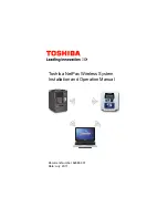
background image

Toshiba NetPac Wireless System 
Installation and Operation Manual

Document Number: 62986-001
Date: July, 2011

Summary of Contents for NetPac

Page 1: ...Toshiba NetPac Wireless System Installation and Operation Manual Document Number 62986 001 Date July 2011 ...

Page 2: ...Toshiba NetPac Wireless System Installation and Operation Manual Document Number 62986 001 Date July 2011 ...

Page 3: ...rsonal computer PC and all ASDs to communicate with each of the other nodes in the network via its mesh network design Wireless communication is accomplished via spread spectrum using the 802 15 4 protocol Once properly configured and using the ASD PRO software system changes node monitoring and configuration updates may be accomplished remotely via a PC See the ASD PRO Software Manual P N 59443 f...

Page 4: ... section on general safety that describes the warning labels and symbols that are used throughout the guide Read the guide completely before installing operating performing maintenance or disposing of this equipment This guide and any accompanying drawings are to be considered a permanent part of the equipment and should be readily available for reference and review Toshiba International Corporati...

Page 5: ...hat you may experience or to provide application information The Support Center is open from 8 a m to 5 p m CST Monday through Friday The Center s toll free number is US 800 231 1412 Fax 713 937 9349 CAN 800 872 2192 MEX 01 800 527 1204 For after hours support follow the directions in the outgoing message when calling You may also contact Toshiba by writing to Toshiba International Corporation 131...

Page 6: ... Protection 6 Power Connections 6 Hardware Installation 7 Software Installation 7 Hardware Installation and Connections 8 Series 2 Transceiver Module Installation 8 RJ 45 Transceiver Installation 9 PC USB Transceiver Installation 9 RJ 45 Transceiver Part Numbering Convention 10 USB Transceiver Part Numbering Convention 10 Software Installation and Verification 11 Driver Port Installation and Setup...

Page 7: ...ide followed by their descriptions and associated symbols When the words DANGER WARNING or CAUTION are used in this guide they will be followed by important safety information that must be carefully adhered to The word DANGER preceded by the safety alert symbol indicates that an imminently hazardous situation exists that if not avoided or if instructions are not followed precisely will result in s...

Page 8: ...ts that if not avoided or if instructions are not followed precisely may result in minor or moderate injury The word CAUTION without the safety alert symbol indicates a potentially hazardous situation exists that if not avoided or if instructions are not followed precisely may result in equipment and property damage CAUTION CAUTION ...

Page 9: ...mbol is comprised of an equilateral triangle enclosing an explosion and indicates that a potentially hazardous situation exists that if not avoided may result in an injury from exploding parts Equipment Warning Labels DO NOT attempt to install operate perform maintenance or dispose of this equipment until you have read and understood all of the product labels and user directions that are contained...

Page 10: ...ions that are contained in this guide and the installation and operation manual of the ASD being utilized Be familiar with the construction and function of the ASD the equipment being utilized and the hazards involved Be able to recognize and properly address hazards associated with the application of motor driven equipment Be trained and authorized to safely energize de energize ground lock out t...

Page 11: ...iba Sales Representative DO NOT install equipment if it is damaged or if it is missing any component s Modification of this equipment is dangerous and is to be performed by factory trained personnel When modifications are required contact your Toshiba Sales Representative Contact your Toshiba Sales Representative to report discrepancies or for assistance if required Disposal Never dispose of elect...

Page 12: ...e performing maintenance and making adjustments to the ASD system Ensure that all system ASD power is off and that the Power and Charge LEDs on the ASD are off before opening the front door or removing the front cover device specific of the ASD Inspect the system components periodically for damaged or improperly functioning parts cleanliness and if using the Toshiba NetPac Wireless System ensure t...

Page 13: ...pins or an improper insertion may result in intermittent operation or system failure Apply power to the ASD only after attaching and or securing the front cover ASD dependent of the ASD Software Installation The system software is to be installed by Qualified Personnel ONLY It is the responsibility of the installer maintenance personnel to ensure that safety and precautionary measures are in place...

Page 14: ...ule Installation 1 Ensure that all system ASD power is off and that the ASD Power and Charge LEDs are off 2 Open the front door or remove the front cover device specific of the ASD to gain access to the control board of the ASD 3 Remove the factory installed Jumper PCB from the J4 connector of the control board note Jumper PCB orientation in the event that a re installation is required the Jumper ...

Page 15: ...ol board CANNOT be used while using the Toshiba NetPac Wireless System RJ 45 Transceiver Installation 1 Perform steps 1 and 2 of the Series 2 Transceiver Module Installation on page 8 2 Insert the transceiver module into the RJ 45 connector of the 7 Series CNU1 or 9 Series S4 ASD terminal board PC USB Transceiver Installation 1 Insert the USB Transceiver Module into any unused USB port of the PC O...

Page 16: ...10 NetPac Wireless System RJ 45 Transceiver Part Numbering Convention USB Transceiver Part Numbering Convention ...

Page 17: ...ust be loaded completely Failure to load both components completely may result in an unexpected motor response intermittent operation or total system failure Follow steps 1 through 7 below to load the driver information Upon completion repeat steps 2 through 6 to load the port information 1 Place the CD that was received with the system into the CD ROM drive Note The Found New Hardware Wizard dial...

Page 18: ...lder driver of the operating system being used i e Vista XP etc and click Next see Figure 2 Note If the PC operating system is unknown right click the My Computer icon of the PC desktop and select Properties The General tab will show the operating system type being used Toshiba Inter Corp USB to NetPac ...

Page 19: ... prompt appears click Continue Anyway 5 In the event that the Files Needed dialog box appears browse to the required file s of the CD ROM drive and click OK Figure 3 Files Needed Dialog Box 6 Upon completion of the installation the Found New Hardware Wizard Completion dialog box appears Click Finish ...

Page 20: ...Pac Wireless System 7 Repeat the procedure once from step 2 on page 11 to load the port information Driver Port Installation and Setup are complete upon the completion of the second execution of step 6 above ...

Page 21: ...ager button 4 At the Device Manager dialog box expand the Universal Serial Bus Controllers folder The Toshiba Inter Corp USB to NetPac file being listed is an indication of a successful driver load 5 At the Device Manager dialog box expand the Port COM LPT folder The Toshiba Inter Corp USB to NetPac file being listed is an indication of a successful port configuration load Note The System Properti...

Page 22: ...ger 7 Close the System Properties dialog box The USB COM port is installed successfully and is ready for use In the event that Toshiba Inter Corp USB to NetPac does not appear as a folder item contact the Toshiba Customer Support Center for assistance ...

Page 23: ... parameter F851 to provide a system disposition in the event of a communications loss 2 Wire and 4 Wire Operation The 7 and 9 Series ASD NetPac Wireless Systems may be set for 2 Wire or 4 Wire operation The ASD must be set to the 2 or 4 wire configuration as indicated on the transceiver module being used see the module part numbering convention on page 10 For the 7 Series ASD place jumpers at the ...

Page 24: ...llation and Operation Manual may be downloaded from web site www toshiba com ind 1 From the www toshiba com ind web site click Industrial Division Drives G9 LV Severe Duty Industrial 2 Click the Setup Software tab 3 Click ASD PRO Software Zip File to download the ASD PRO Software 4 Click the Manuals tab 5 Click ASD PRO Software Operation Manual to download the ASD PRO Software Installation and Ope...

Page 25: ...rd Symbol 3 G General Safety Information 1 H Hardware Installation 7 I Installation Precautions 6 J Jumper PCB 8 P Personnel Protection 6 Port Installation 11 Port Verification 15 Power Connections 6 Power LED 6 8 Q Qualified Personnel 4 R RJ 45 Transceiver Part Number ing Convention 10 S Safety Alert Symbol 1 Series 2 Module 9 shipping damage 4 Signal Words 1 Software Installation 7 Software Inst...

Page 26: ...20 NetPac Wireless System W Wireless Module Installation 8 ...

Page 27: ...BA INTERNATIONAL CORPORATION INDUSTRIAL DIVISION 13131 West Little York Road Houston TX 77041 5807 US 800 231 1412 CAN 800 872 2192 MEX 01 800 527 1204 FAX 713 466 8773 http www toshiba com ind Printed in the U S A ...

Reviews: