Toshiba MV13P2, Service Manual
The Toshiba MV13P2 is a versatile and user-friendly product that offers exceptional performance. To assist you in fully utilizing its features, we proudly provide the Service Manual for free download on our website. Unlock the full potential of your Toshiba MV13P2 with our comprehensive manual, available at manualshive.com.
Share
Download


Reviews:
No comments
Related manuals for MV13P2
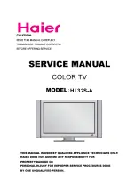
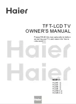
HL32S-A
Brand: Haier Pages: 44
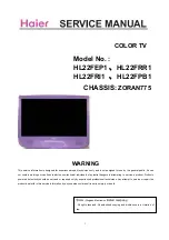
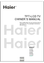
HL22FEP1
Brand: Haier Pages: 53
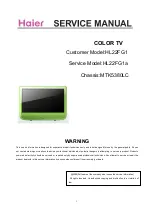
HL22FG1
Brand: Haier Pages: 7
HL26K
Brand: Haier Pages: 42
HL32S-A
Brand: Haier Pages: 44
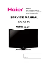
HL42T
Brand: Haier Pages: 46
HL42T
Brand: Haier Pages: 53
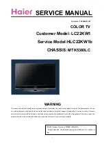
HLC22KW1b
Brand: Haier Pages: 50
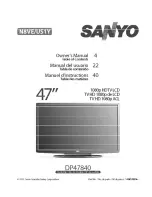
DP47840
Brand: Sanyo Pages: 56
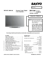
DP47840
Brand: Sanyo Pages: 43
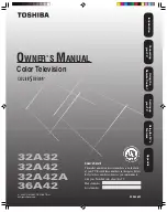
32A32
Brand: Toshiba Pages: 36
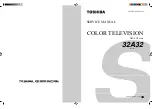
32A32
Brand: Toshiba Pages: 33
HL22FG1
Brand: Haier Pages: 50
HL22FG1
Brand: Haier Pages: 84

40PFK6580
Brand: Philips Pages: 145

CI21N112TZXXEU
Brand: Samsung Pages: 29
BRAVIA KD-85X9500B
Brand: Sony Pages: 127
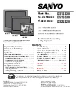
DS19330
Brand: Sanyo Pages: 40


