Toshiba MV 13DM2, Service Manual
The Toshiba MV 13DM2 is a compact and versatile television featuring impressive specifications. To make the most of this device, it is essential to have access to its user manual. Download the free manual from manualshive.com to unlock all the features and functionalities of this exceptional product.
Share
Download


Reviews:
No comments
Related manuals for MV 13DM2

Omnivision VHS PV-C1324
Brand: Panasonic Pages: 4

OmniVision PV-C1324-K
Brand: Panasonic Pages: 8

Omnivision VHS PV-M2046
Brand: Panasonic Pages: 32

UW-17J11VD
Brand: Samsung Pages: 82

28
Brand: Radio Shack Pages: 44
MC132EMG - 13' Tv/vcr Combination
Brand: Magnavox Pages: 2

27MDTR20 - Tv/dvd/vcr Combination
Brand: Magnavox Pages: 4

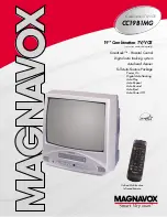
CC19B1MG
Brand: Magnavox Pages: 60

MWC24T5
Brand: Magnavox Pages: 82

MC132EMG/17
Brand: Magnavox Pages: 88

14H3 T1
Brand: Daewoo Pages: 54

WTV11321B
Brand: White-Westinghouse Pages: 32

VV-1309
Brand: Quasar Pages: 44

MGT204D
Brand: Magnavox Pages: 104

W6313CC
Brand: Sylvania Pages: 32

F14H3
Brand: Daewoo Lucoms Pages: 54

GB14H1T
Brand: Daewoo Pages: 23
CC19B1MG
Brand: Magnavox Pages: 2


