background image

Unified Controller


Unified Contr

oller TC-net 100 PCI expr

ess Car

d JTNI6  Instruction Manual

6F8C1450

Instruction Manual

TC-net 100 PCI express Card JTNI6

1450.1.1203


Summary of Contents for JTNI6 Series

Page 1: ...Unified Controller 6F8C1450 Instruction Manual TC net 100 PCI express Card JTNI6 ...

Page 2: ...license 2 Unauthorized reproduction of this Instruction Manual in whole or a part is prohibited 3 The contents of this document subject to change without prior notice 4 We extended all possible means to ensure the contents of this Instruction Manual however if you have any questions found any errors or noticed anything wrong please contact us PCI express and PCIe are registered trademarks of the P...

Page 3: ... A serious injury indicates loss of sight injury burns high low temperature electric shock broken bones or intoxication that will have aftereffects and require hospitalization or long term hospital visits for healing 2 An injury indicates an injury burn or electric shock that does not need hospitalization or long term hospital visits for healing 3 A property damage indicates consequential damage i...

Page 4: ... to rapid temperature changes A place with low or high temperature outside of the installation condition A place with high humidity outside of the installation condition A place with direct sunlight A place near equipment generating strong radio waves or magnetic fields It may cause accidents Mandatory For installation and wiring of the system observe the installation conditions and methods descri...

Page 5: ...rounded metal part to discharge the static electricity on your body before touching the device or board Otherwise charged static electricity on your body can cause malfunction or failure Mandatory Use soft cloth to clean the device module or board Use water dipped and squeezed cloth to clean it if dirty Leaving the device dirty can cause mistaken or malfunction Mandatory Place a board or module re...

Page 6: ...e an electric shock fire injury or failure Upon faulty operation or failure contact Toshiba s branch office or service offices Mandatory Before using check that the power capacity frequency voltage and regulation comply with the device specifications If not it may cause damage of the device or fire due to overheat as well as not obtaining the original performance of the device Mandatory Turn off p...

Page 7: ...rwise it can cause malfunction or failure and lose the safety of the device as well Prohibited Do not forcibly bend or pull or distort the power cord and other cables Otherwise they can be cut off or cause overheat Prohibited Do not enter wire scrapes or other foreign debris into the device Also do not insert metal parts into them They can cause fire or accidents 5 Safety Precautions on Disposal C...

Page 8: ...tems Note 3 Special considerations indicate sufficient discussions with Toshiba s engineers to construct a safe system e g employing fool proof design fail safe design or redundant design Disclaimer Toshiba shall not be responsible for any damage caused by a fire or an earthquake for which Toshiba is not responsible for acts of a third party other accidents the user s willful acts or negligence mi...

Page 9: ...1 First of all make sure to read Safety precautions in order to use the equipment correctly After reading this manual keep it in a safe place so that you can read it wherever necessary Related Documents The documents related to this manual are shown below Unified Controller nv series TC net 100 PCI express Card JTNI6 Instruction Manual 6F8C1450 this document Unified Controller nv series TC net 100...

Page 10: ...S etc are generated 3 Place where the product may be exposed to vibration or shock 4 Environment of low or high temperature deviating from the conditions for installation specified herein 5 Very humid place 3 If the ambient temperature or the internal temperature of the equipment has arisen too high or if the equipment has developed a fault stop using it switch power off and contact the nearest To...

Page 11: ...f Parts and Their Functions 5 2 1 Names and Functions of the Parts 6 Chapter 3 Switch Setting 9 3 1 Setting Switches 11 Chapter 4 Installation and Wiring 13 4 1 Before Starting 14 4 2 Installation 15 4 3 Connection 17 4 4 Card Replacement 18 Chapter 5 Maintenance and Inspection 19 5 1 Inspection 21 5 2 Troubleshooting 22 5 3 Life Limited Parts 22 CONTENTS ...

Page 12: ... A 2 TC net 100 Specifications 26 Appendix B Dimensions 27 B 1 Outside Dimensions 28 Appendix C External Connectors 29 C 1 2 Core MT RJ Connector Socket 30 C 2 EN 8 pin Modular Connector Socket 30 Appendix D Related Products 31 Appendix E Hexadecimal Conversion Tables 33 ...

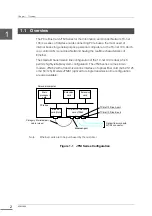
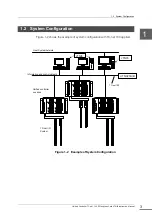
Page 13: ...1 Chapter 1 Overview 1 1 Overview 2 1 2 System Configuration 3 ...

Page 14: ...dual which permits highly reliable system configuration The JTNI6 series comes in two models JTNI62 with a transmission line interface of optical fiber cord GI 62 5 125 or GI 50 125 Models JTNI61 optical for single transmission line configuration are also available Figure 1 1 JTNI Series Configuration Note Ethernet cards are to be purchased by the customer Main processor card Extension card Extens...

Page 15: ...on Manual 3 1 2 System Configuration Figure 1 2 shows the example of system configuration with TC net 100 applied Figure 1 2 Example of System Configuration Host System network Information and control network JTNI6 JTNI6 UTNH23A B TC net 100 TC net I O System Unified controller nv series ...

Page 16: ...Chapter 1 Overview 6F8C1450 4 ...

Page 17: ...5 Chapter 2 Names of Parts and Their Functions 2 1 Names and Functions of the Parts 6 ...

Page 18: ...unctions of JTNI6 are described here JTNI61 panel JTNI61 EN TN A LINK ACT ACT LINK JTNI62 panel JTNI62 EN TN B TN A LINK ACT ACT LINK ACT LINK DIP SW STN L STN H Ethernet 光T R 光T R Note The JTNI61 for single systems have the TN A connector only they have no TN B connector Figure 2 1 The card appearance Opt Opt EN TN A TN B ...

Page 19: ...B ACT Indicates TC net 100 transmission Turned on and off by the hardware It lights when transmission is made to line B It blinks or remains lit during normal operation LINK Indicates that line B is linked to the hub It is turned on and off by the hardware It remains lit during normal operation EN connector ACT Indicates Ethernet transmission Turned on and off by the hardware It lights when transm...

Page 20: ...b OFF Not connected to hub ON TN A ACT green TC net 100 line A transmission reception ON frame being transmitted received OFF No transmission ON TN B LINK green TC net 100 line B linkage ON Linked normally to hub OFF Not connected to hub ON TN B ACT green TC net 100 line B transmission reception ON frame being transmitted received OFF No transmission ON 2 External connectors TN A TN B TC net 100 i...

Page 21: ...9 Chapter 3 Switch Setting 3 1 Setting switches 11 ...

Page 22: ...ductive mat before setting the switches Failure to observe this could cause the product to fail due to static Subjecting the product to strong stress inside may cause trouble Exercise caution to keep your hands and tools off other parts than the switches in setting them Do not change the switch settings unless necessary Wrong settings will prevent normal operation Be sure to set station addresses ...

Page 23: ...ess unique to the same segment Up to 254 station addresses from 01h to FEh can be set Table 3 1 Station Address Setting Name Location Setting Station address STN H STN L Setting range 01 to FE h H H address 0 to F h L L address 0 to F h Set a station address in hexadecimals The address 28 corresponds to 1C in hexadecimals h So turn STN H to 1 and STN L to C Operation mode setting MODE 4 bit DIP sw...

Page 24: ...Chapter 3 Switch Setting 6F8C1450 12 12 ...

Page 25: ...ssion cables are described here referring to an example showing a general PC To install the card carefully read the manual supplied with your personal computer Be sure to check the working conditions and methods before installing the card 4 1 Before Starting 14 4 2 Installation 15 4 3 Connection 17 4 4 Card Replacement 18 ...

Page 26: ... and do not subject the card to condensation or other abrupt temperature change Working Method Note Do not touch other than those parts necessary for the work Be careful not to loose the removed screws and not to drop them inside the computer If you find an error or failure Contact one of Toshiba service representatives Be careful not to be injured by the sharp projections on the extension board I...

Page 27: ...lug Touching the live parts inside could cause electric shock 3 Installing the card Install the card as described below CAUTION Do not touch the heat sink of the CPU The heat sink is still hot after switching power off possibly causing burns Important To install an extension board take adequate measures against static by wearing gloves for example Note The extension slot is subject to restrictions...

Page 28: ...p 1 4 Placing the personal computer cover back on For the procedure of placing the computer cover back on refer to the instruction manual of the PC which you are installing the cord to 5 Installing the front panel if necessary For details refer to the instruction manual of the PC which you are installing the card to The installation procedure has been completed Extension card Extension card panel ...

Page 29: ... not directly affect the connectors The allowable bending radius for the cables connected and clamps is shown in Table 4 1 Make sure that the cable bends do not exceed the specified radius Table 4 1 Allowable Cable Bending Radius Allowable Bending Radius mm Cable Cable Outside Diameter mm Clamped Connected Optical fiber cable 5 50 50 Twisted pair cable 5 2 21 52 Note Optical fiber cables vary in a...

Page 30: ...ingers and unlock the connector Pull out the cable Similarly pull out the Ethernet cable Attach tags or seals to the line A B and Ethernet cables for identification later 3 Remove the cover from the personal computer remove the M3 screws from the JTNI card with a Phillips screwdriver and pull out the card 4 When a new JTNI card is ready set the setting switches to the same positions as those on th...

Page 31: ...19 Chapter 5 Maintenance and Inspection 5 1 Inspection 21 5 2 Troubleshooting 22 5 3 Life Limited Parts 22 ...

Page 32: ...e human body before touching it for cleaning for example Be careful not to change the switch settings when cleaning the product Also exercise care not to strain the cables Careless touch of the cables may strain them to possibly cause operation errors and accidents When something abnormal occurs such as failure to turn on the power stop using the equipment and contact one of Toshiba service repres...

Page 33: ...hiba service representatives 3 Ventilation ports Check the ventilation ports in the personal computer where the card is installed that they are free of dust and stains If the ventilation ports are clogged up with foreign matter remove it using a vacuum cleaner or a soft cloth 4 Indoor environment Check the temperature and humidity of the room where the product is installed that they meet the produ...

Page 34: ...condition for a long period of time Contact one of Toshiba service representatives for advice on their replacement Table 5 1 Life Limited Parts and Recommended Replacement Periods Part Name Recommended Replacement Period Optical module After 10 years of usage the optical output power shall be measured every year or contact one of Toshiba s service representatives for measurement If the optical pow...

Page 35: ...23 Appendix A Specifications A 1 General Specifications 24 A 2 TC net 100 Specifications 26 ...

Page 36: ...ensation Storage temperature 40 to 70 C Storage humidity 5 to 90 RH without condensation Working altitude 2000 m Dust density 0 3mg m 3 or less no conductive dust Corrosive gas None Vibration resistance 1 96m s2 or less IEC 60068 2 6 9 150Hz 1cycle Impact resistance 19 6 m s 2 during operation Natural fall Packing fall 30 cm JIS Z0200 level4 compliant Grounding Type D grounding grounding resistanc...

Page 37: ...s at 3 3Vdc Power consumption at rated voltage input 10W or less Module dimension 84 49 H x166 65 D mm PCI express half size Hot swap Impossible Power down detection Hard reset supplied from personal computer 3 3V low voltage detection LAN interface TC net 100 lines A and B 100BASE TXx1 Bus interface PCI express Ver1 1 compliant PCI operation mode EndPoint mode PCI transmission mode PIO access DMA...

Page 38: ...es maximum per system Transmission mode Scan transmission High speed cycle 1 ms to 160 ms Medium speed cycle 2 ms to 1 000 ms Low speed cycle 2 ms to 10 000 ms Message transmission TCP IP message transmission reception Scan transmission capacity 576 blocks per node 36kW node High speed scan 64 blocks Medium speed scan 128 blocks Low speed scan 384 blocks Throughput Approx 3 8 Mwords s with 32 node...

Page 39: ...27 Appendix B Dimensions B 1 Outside Dimensions 28 ...

Page 40: ... B Dimensions 6F8C1450 28 B 1 Outside Dimensions Unit mm Figure B 1 Outside Dimensions 166 65 80 00 84 49 JTNI62 EN TN B TN A LINK ACT ACT LINK ACT LINK JTNI61 EN TN A LINK ACT ACT LINK 121 02 21 6 21 6 121 02 ...

Page 41: ...29 Appendix C External Connectors C 1 2 Core MT RJ Connector Socket 30 C 2 EN 8 pin Modular Connector Socket 30 ...

Page 42: ... 100 MT RJ Connector Pin Assignments Pin Signal Description 1 TX Transmission 2 RX Reception C 2 EN 8 pin Modular Connector Socket Table C 2 EN Connector Pin Assignments Pin Signal Description 1 TD Transmission 2 TD Transmission 3 RD Reception 4 Unused 5 Unused 6 RD Reception 7 Unused 8 Unused ...

Page 43: ...31 Appendix D Related Products ...

Page 44: ...roducts 6F8C1450 32 Table D 1 Related Products Product Description Remarks Optical fiber cord Optical fiber cord with MT RJ optical connector at both ends Electric twisted pair cable Category 5 twisted pair straight cable ...

Page 45: ...33 Appendix E Hexadecimal Conversion Tables ...

Page 46: ... 48 104 68 9 9 41 29 73 49 105 69 10 A 42 2A 74 4A 106 6A 11 B 43 2B 75 4B 107 6B 12 C 44 2C 76 4C 108 6C 13 D 45 2D 77 4D 109 6D 14 E 46 2E 78 4E 110 6E 15 F 47 2F 79 4F 111 6F 16 10 48 30 80 50 112 70 17 11 49 31 81 51 113 71 18 12 50 32 82 52 114 72 19 13 51 33 83 53 115 73 20 14 52 34 84 54 116 74 21 15 53 35 85 55 117 75 22 16 54 36 86 56 118 76 23 17 55 37 87 57 119 77 24 18 56 38 88 58 120 ...

Page 47: ...32 E8 137 89 169 A9 201 C9 233 E9 138 8A 170 AA 202 CA 234 EA 139 8B 171 AB 203 CB 235 EB 140 8C 172 AC 204 CC 236 EC 141 8D 173 AD 205 CD 237 ED 142 8E 174 AE 206 CE 238 EE 143 8F 175 AF 207 CF 239 EF 144 90 176 B0 208 D0 240 F0 145 91 177 B1 209 D1 241 F1 146 92 178 B2 210 D2 242 F2 147 93 179 B3 211 D3 243 F3 148 94 180 B4 212 D4 244 F4 149 95 181 B5 213 D5 245 F5 150 96 182 B6 214 D6 246 F6 15...

Page 48: ...Appendix E Hexadecimal Conversion Tables 6F8C1450 36 36 ...

Page 49: ...12 Toshiba Corporation 2012 All Right Reserved No part of this document may be reproduced without the prior written consent of Toshiba First Edition Social Infrastructure Systems Company Automation Products Facility Solution Division 1 1 Shibaura 1 chome Minato ku Tokyo 105 8001 Japan ...

Page 50: ...Unified Controller TC net 100 PCI express Card JTNI6 Instruction Manual 1450 1 1203 ...

Reviews: