


For Customer Use
Enter below the Serial #
w h i c h i s l o c a t e d o n t h e
bottom of the cabinet. Retain
this information for future ref-
erence.
Model # IK-HD1D
Serial #
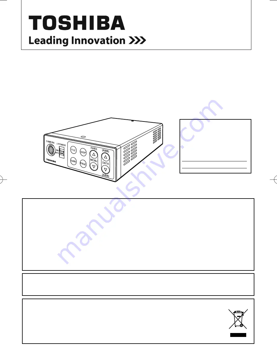
CAMERA CONTROL UNIT
INSTRUCTION MANUAL
FCC NOTICE
This equipment has been tested and found to comply with the limits for a Class A digital device, pursu-
ant to Part 15 of the FCC Rules. These limits are designed to provide reasonable protection against
harmful interference when the equipment is operated in a commercial environment. This equipment
generates, uses, and can radiate radio frequency energy and, if not installed and used in accordance
with the instruction manual, may cause harmful interference to radio communications. Operation of this
equipment in a residential area is likely to cause harmful interference in which case the user will be
required to correct the interference at his own expense.
USER-INSTALLER CAUTION: Your authority to operate this FCC verified equipment could be voided if
you make changes or modifications not expressly approved by the party responsible for compliance to
Part 15 of the FCC Rules.
This Class A digital apparatus complies with Canadian ICES-003.
Cet appareil numérique de la classe A est comforme à la norme NMB-003 du Canada.
Following information is only for EU-member states:
The use of the symbol indicates that this product may not be treated as household waste.
By ensuring this product is disposed of correctly, you will help prevent potential negative
consequences for the environment and human health, which could otherwise be caused by
inappropriate waste handling of this product. For more detailed information about the take-
back and recycling of this product, please contact your supplier where you purchased the
product or consult.
This manual is made from recycled paper.
IK-HD1D
IK-HD1D̲EN.indd 1
IK-HD1D̲EN.indd 1
2008/04/16 17:53:32
2008/04/16 17:53:32


