background image


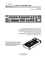
Toshiba HX- MU 901 keyboard 


Technical information 


Version 1.1 


By HansO, 2001 
Checked and enhanced by Bas Kornalijnslijper 

 
The information in this article is gathered by opening up a well-functioning  
HX-MU901 musical keyboard and checking all connections. No guarantee is given 
that this information is correct. You may use this information at your own risk. 
 
1 Specification ..........................................................................................................2 
2 Parts........................................................................................................................2 

2.1 Key 

print ........................................................................................................2 

2.2 Multi 

sensor 

print...........................................................................................2 

2.3 Wiring ............................................................................................................2 

Circuit diagram of key print...................................................................................2 

Block diagram of multi sensor print ......................................................................4 

Connections to multi sensor...................................................................................5 

5.1 Circuit 

diagram 

of multi sensor .....................................................................5 

6 Wiring ....................................................................................................................6 

6.1 

Key-print15 pen connector out part to multi sensor print..............................6 

6.2 

Key print15 pen connector in line part to multi sensor print .........................6 

6.3 External 

connector .........................................................................................7 


Summary of Contents for HX-MU 901

Page 1: ...n that this information is correct You may use this information at your own risk 1 Specification 2 2 Parts 2 2 1 Key print 2 2 2 Multi sensor print 2 2 3 Wiring 2 3 Circuit diagram of key print 2 4 Block diagram of multi sensor print 4 5 Connections to multi sensor 5 5 1 Circuit diagram of multi sensor 5 6 Wiring 6 6 1 Key print15 pen connector out part to multi sensor print 6 6 2 Key print15 pen ...

Page 2: ...he keys 49 diodes a printed circuits that implements the matrix as shown in the circuit diagram 49 diodes 2 2 Multi sensor print A printed circuit underneath the multi sensor with wires from keyboard print to connection print at multi sensor Connector for in lines 7 Connector for out lines 8 Two connectors for outside wiring Connector for multi sensor flexible wires 2 3 Wiring Wiring connects all ...

Page 3: ...3 ...

Page 4: ...iagram of multi sensor print 8 red 1 green Out lines keyboard To external connector 2 1 Multi sensor 14 diodes 10 brown white 1 black 8 greenwhite 1 violet 7 red In lines keyboard To external connector 1 1 red 4 ...

Page 5: ...ines and has two separate out lines black and white from external connector 2 The numbering for the multi sensor connector seen from the bottom side of the print is shown in the next figure 5 1 Circuit diagram of multi sensor Notes Numbering of the diodes is the numbering of the multi sensor connector Numbers at the top are the numbers of the external connector 2 5 ...

Page 6: ...y print15 pen connector in line part to multi sensor print Connects Key print connector in lines part to external connector 2 multi sensor Key print Multi sensor print Key print15 pen connector in part To external connector 2 9 7 Red Black 1 10 6 Blue Blue 2 11 5 Black Blue white 8 12 4 White Purple 7 13 3 Yellow Light green 5 14 2 Orange Grey 4 15 1 Violet Light blue 3 brown 6 White 9 Brown white...

Page 7: ...e white 13 Violet 14 Light green 15 Grey 16 Light blue 17 White 18 Pink 19 Black 20 Shielding Notes These wires are not connected to the keyboard switches Wire 18 pink is not connected in the keyboard Wire 20 shielding is only connected to the chassis When one of the wires in the cable is broken you can substitute the broken one with either wire 18 or 20 7 ...

Reviews: