Toshiba D-KR4SU, Service Manual
The Toshiba D-KR4SU Service Manual is a comprehensive and essential resource for users of this exceptional product. Accessible for free download at manualshive.com, this user manual provides step-by-step instructions, troubleshooting tips, and detailed explanations, ensuring a seamless experience with the Toshiba D-KR4SU.
Share
Download


Reviews:
No comments
Related manuals for D-KR4SU
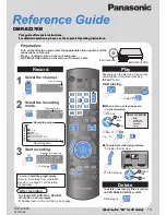
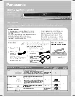
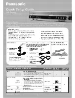
DIGA DMR-ES15
Brand: Panasonic Pages: 2
Diga DMR-EH55
Brand: Panasonic Pages: 2
Diga DMR-EZ28
Brand: Panasonic Pages: 2

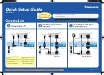
Diga DMR-ES10EB
Brand: Panasonic Pages: 6
Diga DMR-ES20DEB
Brand: Panasonic Pages: 6
Diga DMR-EZ27EB
Brand: Panasonic Pages: 2
Diga DMR-EZ17
Brand: Panasonic Pages: 2
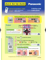
Diga DMR-ES35V
Brand: Panasonic Pages: 2
Diga DMR-ES30V
Brand: Panasonic Pages: 2
Diga DMR-ES40V
Brand: Panasonic Pages: 4
Diga DMR-EX75EB
Brand: Panasonic Pages: 4
Diga DMR-EZ48V
Brand: Panasonic Pages: 2
Diga DMR-EZ37
Brand: Panasonic Pages: 8
Diga DMR-EZ45VEBS
Brand: Panasonic Pages: 4
DMR-EX75
Brand: Panasonic Pages: 4
DMR-ES36V
Brand: Panasonic Pages: 2
DMREA38V - DVD RECORDER - MULTI LANGUAGE
Brand: Panasonic Pages: 2
Diga DMR-EZ27
Brand: Panasonic Pages: 8


