Toshiba Compliant Manager BMS-CM1280FTLE, Installation Manual
The Toshiba Compliant Manager BMS-CM1280FTLE is an advanced Building Management System (BMS) that ensures seamless integration and control of various building equipment. To facilitate its easy installation, a comprehensive Installation Manual is available for download completely free of charge at manualshive.com. Get the most out of your BMS-CM1280FTLE by referring to this manual!
Share
Download


Reviews:
No comments
Related manuals for Compliant Manager BMS-CM1280FTLE
816
Brand: IDS Pages: 64
NetworX Series
Brand: GE Pages: 24
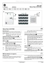
Interlogix Aritech ATS1155
Brand: GE Pages: 2
KTD-404
Brand: KALATEL Pages: 8
NX-148E - Security NetworX LCD Keypad
Brand: GE Pages: 24
OfficeServ ITP-5121D
Brand: Samsung Pages: 2
DS 5000 Series
Brand: Samsung Pages: 91
DS 5007S KEYSET
Brand: Samsung Pages: 20
OfficeServ 7200
Brand: Samsung Pages: 43
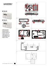
SPCK420
Brand: Vanderbilt Pages: 11
SCF SERIES
Brand: AC Tech Pages: 2
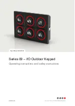
09 Series
Brand: eao Pages: 19
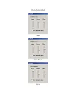
CK2.2
Brand: B&K Pages: 6
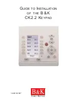
CK2.2
Brand: B&K Pages: 12
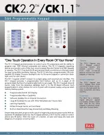
CK1.1
Brand: B&K Pages: 2
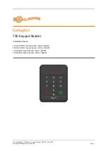
T30
Brand: Gallagher Pages: 13
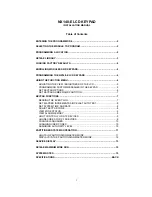
System 236i
Brand: C&K systems Pages: 40
NX148-E
Brand: CADDX Pages: 16


