background image

Summary of Contents for Carrier RBC-AX22CUL

Page 1: ...UL Generic Wireless remote controller model name and signal receiving unit RBC AX22CUL WX TA01 UES Wireless remote controller model name TOSHIBA _arrler Wireless remote controller WX TA01UES O Q O Signal receiving unit Installation Manual Remote controller for air conditioner Split type Manuel D installation Tel6commande pour climatiseur Type split 1 8 ...

Page 2: ...2 INSTALLATION OF SIGNAL RECEIVING UNIT 2 3 HOWTO PERFORM CABLING OF SIGNAL RECEIVING UNIT 4 4 REQUIREMENT 4 5 HOWTO SETTHE ROOM TEMPERATURE SENSOR 5 6 HOWTO SETTHE ADDRESS SWITCH 5 7 SLIDE SWITCH 5 8 SELF DIAGNOSIS TABLE AND MEASURES 5 9 HOWTO SET UP FORTHE HIGH CEILING 6 10 HOWTO HANDLETHE REMOTE CONTROLLER 6 1 1 CAUTIONS FOR INSTALLATION OF THE REMOTE CONTROLLER 6 12 EXPLANATION TO CUSTOMERS 6 ...

Page 3: ...hen open the Suction grille suction grille Fig A fixing knob Suction grille 2 Remove the screws 2 pcs which are fixing the wire guard Using clamps mounted to the wire guard hang up the wire guard Do not remove the fixing screws of clamps of the indoor unit Fig B Clamps NOTE After installation of the signal receiving unit be sure to mount the wire guard as original Fig C Fig C Screws Wire guard 2 E...

Page 4: ...e from the signal receiving unit along cables of the louver motor and others and then fix it with the cord clamp Fig G It s connected to a connection of Remote control wire through a hole for Remote control wire Fig H 9 After all connections have been made install wire guard and suction grill before doing the TEST RUN Fig D Fig E Fig F Fig H Panel i Screw Suction grille lamp Signal receiving unit ...

Page 5: ...hen setting the wired remote controller as the sub exchange the address connector at the rear of RC board of wired remote controller from main to sub remote controller When setting the wireless remote controller as the sub turn No 3 of DIP switch S003 on RC board of signal receiving unit from OFF to ON To operate an indoor unit by Wireless Wired 2 remote controllers remote controller kit remote co...

Page 6: ...ion For selecting of the remote controller address refer to Owner s Manual Change the address of the signal receiving unit by removing Display of Address Address Address Address remote controller screws of P C board cover of the add FILL 2 5 signal receiving unit After then fix the cover with Address switch _Address switch of 7_ b 1 2 3 7_ _ 1 2 3 position of signal signal receiving r_q_ unit can ...

Page 7: ..._ button at the position to be fixed Replacement of battery 1 Holding the both ends of the cover and remove it by sliding downward 2 Correctly insert 2 AAA alkali batteries matching and polarities with indications 3 Push ACL button with something tipped and attach the cover _ ACLbutton Cover Mounting screw Truss tapping _0 16 x 0 63 pull it toward you 1 CAUTIONS FOR INSTALLATION OFTHE REMOTE CONTR...

Page 8: ...TE Do not use the forced TEST RUN for cases other than the TEST RUN because it applies an excessive load to the devices _1 In case of wireless remote controller Be sure to set the_ I air speed to __ Procedure Operation contents Turn on power of the set After installation the operation is not accepted for 5 minutes when the power has been turned on at the first time and 1 minute when the power has ...

Page 9: ... 9 3 COMMENT ACCOMPLIR CE CABLAGE DE L UNITI_ DE RE_CEPTION DES SIGNAUX 11 4 CONDITIONS REQUISES 11 5 MODE DE RC GLAGE DU DC TECTEUR DETEMPC RATURE AMBIANTE 12 6 MODE DE RC GLAGE DU COMMUTATEUR D ADRESSE 12 7 CURSEUR 12 8 TABLEAU D AUTODIAGNOSTIC ET MESURES 12 9 COMMENT FAIRE LA CONFIGURATION POUR LE PLALFOND HAUT 13 10 MODE DE MANIPULATION DE LATE_LE_COMMANDE 13 1 1 PR_ CAUTIONS CONCERNANT L3NSTA...

Page 10: ...ouvrez la gritle d aspiration Fig A Fig A Pommeau de fixation Grille d aspiration de la grille d aspiration 2 Retirer les vis 2 vis de fixation de ta protection du c bte Avec les agrafes montees sur la protection du cSbte suspendez la protection du c bte _ Ne retirez pastes vis de fixation des agrafes de I unite interieure Fig B Agrafes Vis REMARQUE Lorsque le montage de t unite de reception des s...

Page 11: ...ec le serre fils Fig G _ II est relie a un rapport de fit de ta tetecommande a travers un trou pour fit de ta telecommande Fig H 9 Une fois toutes les connexions effectuees mettre en place ta grille d aspiration avant de proceder a t essai de fonctionnement Ne pas utiliser de tournevis eIectrique pour serrer les vis Fig D Fig E Panneaul Panneau lateral Tournevis plat Enveloppez le d un ruban en vi...

Page 12: ...necteur d adresse ptacee au dos de la carte a circuit imprime de la tetecommande filaire atlant de ta telecommande principale a la telecommande secondaire Lors de ta configuration de ta tetecommande sans fit en tant que telecommande secondaire faites passer te commutateur DIP n 3 S003 de ta carte a circuit imprime de I unite de reception des signaux de OFF ARRET a ON MARCHE Commande d une unit_ in...

Page 13: ...e telecommande reportez vous au Manuel du proprietaire Modifiez I adresse de I unite de reception des signaux en retirant Aftichage de Adresse Adresse Adresse Adresse I adresse de les vis du couverole de la carte te _ de RLL B 5 circuit imprime de I unite de reception des signaux Positiondu Lecommutateur 7 _ 1 2 3 tateur d ad de runite de _ _ Fixez ensuite le couvercle avec d adressede receptionde...

Page 14: ...DE En cas d utilisation de la t61_commande mont6e sur le mur etc V_s de fixation FHetage renfurce Verifiez si te signal est re_u correctement en appuyant sur ta touche Q dans ta position de fixation Remplacement des piles 1 Tenez tes deux extremites du couvercte et enlevezde en te faisant gtisser vers te bas 2 Inserez correctement 2 piles atcalines AAA en faisant correspondre les polarites et avec...

Page 15: ... pour LESSAI DE FONCTIONNEMENT car il applique une charge excessive aux dispositifs _1 En cas de t_l_commande sans fil ve t ot oosu 2 _ 3 4 5 6 Procedure Opicrations Mettez le systicme sous tension Aprics le montage le systicme ne fonctionne pas pendant les 5 minutes qui suivent sa premiicre mise sous tension et pendant la minute qui suit les mises sous tension successives Faites un essai de fonct...

Page 16: ...85464369215000 EH99677401 ...
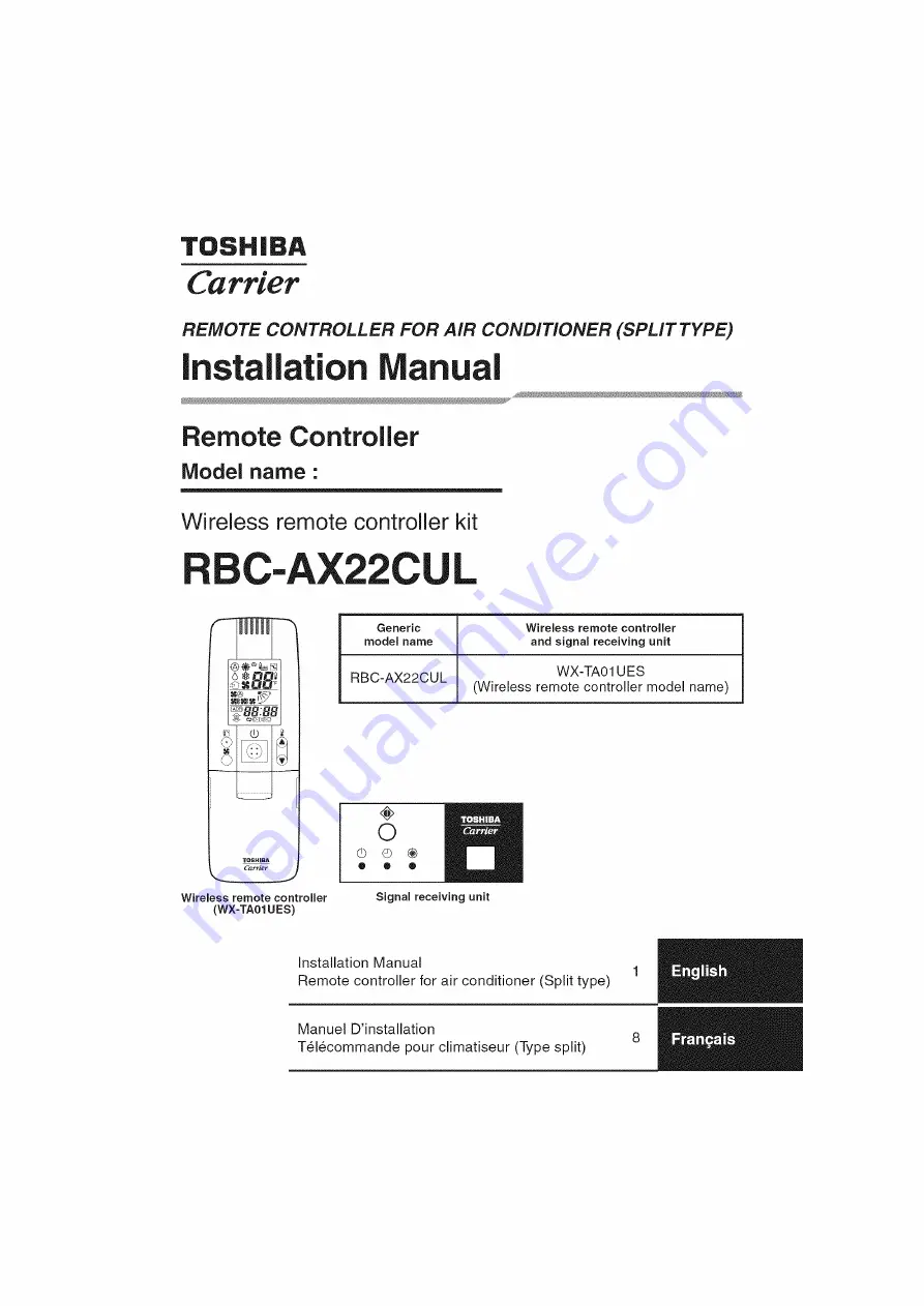
Reviews: