background image

035-000051-001

Page 1 of 60

MMD IOM 1.2 11-10-2020

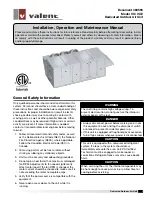
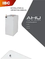
Vertical Air Handling Unit

Installation, Operation and Maintenance Manual

Model name:

For Commercial Use

MMD-AP0120VHG2UL
MMD-AP0180VHG2UL
MMD-AP0240VHG2UL
MMD-AP0300VHG2UL
MMD-AP0360VHG2UL
MMD-AP0420VHG2UL
MMD-AP0480VHG2UL
MMD-AP0600VHG2UL

Summary of Contents for Carrier MMD-AP0180VHG2UL

Page 1: ...0 2020 Vertical Air Handling Unit Installation Operation and Maintenance Manual Model name For Commercial Use MMD AP0120VHG2UL MMD AP0180VHG2UL MMD AP0240VHG2UL MMD AP0300VHG2UL MMD AP0360VHG2UL MMD AP0420VHG2UL MMD AP0480VHG2UL MMD AP0600VHG2UL ...

Page 2: ...035 000051 001 Page 2 of 60 MMD IOM 1 2 11 10 2020 THIS PAGE INTENTIONALLY LEFT BLANK ...

Page 3: ...035 000051 001 Page 3 of 60 MMD IOM 1 2 11 10 2020 Installa on Start Up and Service Instruc ons MMD Series Air Handling Unit Installation Operation and Maintenance Manual ...

Page 4: ...035 000051 001 Page 4 of 60 MMD IOM 1 2 11 10 2020 THIS PAGE INTENTIONALLY LEFT BLANK ...

Page 5: ...LS be sure that the area is clear of personnel DO NOT attempt to handle access covers and re movable panels on outdoor units when winds are strong or gusting until you have sufficient help to control them Make sure panels are properly se cured while repairs are being made to a unit DO NOT remove access panel fasteners or open access doors until fan is completely stopped Pres sure developed by a mo...

Page 6: ...035 000051 001 Page 6 of 60 MMD IOM 1 2 11 10 2020 PRODUCT NOMENCLATURE ...

Page 7: ...hick filter or 2 thick filter To use with 4 thick filter filter remove 2 filter remove filter rail and add field supplied 4 thick filter 3 Return air Grille s and duct collars are field provided and field installed 4 Plenums have return air duct openings on front right and le sides Front and right sides have flat co vers that can be relocated as needed Opening in rear can be cut in the field Notes ...

Page 8: ...been de ployed will not be considered for compensation This position is taken regardless of whether the source of the moisture was specified as a po tential failure mode in the applicable building code or not A freeze burst cracked drain pan failed weld or corrosion induced leak are some of the potential failure modes that are mitigated when an auxiliary pan is properly installed Pro fessional ins...

Page 9: ...035 000051 001 Page 9 of 60 MMD IOM 1 2 11 10 2020 INSTALLATION Figure 1 Return Configurations and Unit Orientations ...

Page 10: ...RONT ACCESS ONLY 2 RECOMMENDED BUT NOT NECESSARY ALLOW 12 ON RIGHT AND LEFT SIDES FOR SIGNIFICANT BUT INFREQUENT SERVICE PROCEDURES SUCH AS DRAIN PAN OR COIL REPLACEMENT 3 WHEN UNIT IS INSTALLED HORIZONTALLY LYING ON RIGHT SIDE CLEARANCES REMAIN THE SAME AS INDICATED ABOVE EXCEPT TRAP CLEARANCE EX TENDS BELOW THE UNIT ...

Page 11: ...trans mission to the structure 2 When the connecting return air duct is smaller than the coil inlet opening construct the transi tion piece so that the vertical and horizontal di mensions of the transition piece do not increase more then one inch for every seven inches of length of the transition piece 3 Provide at least three feet of straight duct work preceding the unit inlet INSTALLATION WARNIN...

Page 12: ...035 000051 001 Page 12 of 60 MMD IOM 1 2 11 10 2020 Figure 4a CEILING SUSPENSION DETAILS MMD AIR HANDLER ...

Page 13: ...of heat sink wet cloth or other method to prevent damage to liquid line and suction line components see Figure 4b Size and install refrigerant lines in accord ance with the condensing unit manufactur er s instructions Provide insulation on the suction line to prevent condensation Pro vide insulation on the liquid line if unit to be used for heat pump service or if otherwise required System Design ...

Page 14: ...screws holding heater support feet to the blower deck 4 Remove 4 screws that mount the heater to the heater bulkhead Handle heater carefully to avoid damaging the wire heating elements Remove heater from the unit DANGER WARNING Hazardous voltage Only qualified personnel must install the electrical service Dis connect and Lock Out all incoming power sources before connecting to electrical service W...

Page 15: ...bottom Next slide the switch plate toward the heater plate line up the two holes and re install the two screws The final assembly is shorter to match the shallower depth of the 1 1 5 2 0 ton size cabinets DANGER WARNING Hazardous voltage Only qualified personnel must install the electrical service Dis connect and Lock Out all incoming power sources before connecting to electrical service Fig 6b He...

Page 16: ...move plate on the heater bulkhead 4 screws 7 Install heater by carefully supporting the heater and inserting it into the opening in the heater bulk head NOTE Make sure to guide the pin into the hole at the back of the heater shroud Secure the heater to the bulkhead with 4 screws 8 Connect 2 wiring harnesses male to the matching female receptacles in the blower deck 9 Connect field wiring to the br...

Page 17: ... behind the blower access door or other convenient location Control voltage wiring DANGER NEVER enter an enclosed fan cabinet or reach into a unit while the fan is running LOCK OPEN AND TAG the fan motor power dis connect switch before working on a fan Take fuses with you and note removal on tag Electric shock can cause personal injury or death LOCK OPEN AND TAG the electric heat coil power discon...

Page 18: ...EC as well as applicable local codes In addition all field wiring must conform to the Class II temperature limitations described in the NEC Refer to factory wiring diagrams installed in the unit Use the MCA and MOPD from the nameplate or electric heat nameplate or Electrical Ratings page 30 to size power supply wiring and overcur rent protection device Installation must comply with NEC and local c...

Page 19: ...035 000051 001 Page 19 of 60 MMD IOM 1 2 11 10 2020 INSTALLATION ELECTRICAL cont d TYPICAL WIRING DIAGRAM ...

Page 20: ...035 000051 001 Page 20 of 60 MMD IOM 1 2 11 10 2020 INSTALLATION ELECTRICAL cont d TYPICAL WIRING ELECTRIC HEAT TYPICAL WIRING DIAGRAMS Electric Heat 1 6kW and 8 9 5kW TYPICAL WIRING ELECTRIC HEAT 3 ...

Page 21: ...and access doors Make sure filter me dia is clean before starting unit Replace filter if neces sary 3 Verify that discharge ductwork and input plenum are in place and secure 4 Apply power to unit If unit is equipped with on board power switch es turn switch es to the On position 5 Insure that controls system has power and is operational 6 Force control system to send fan on signal and speed signal...

Page 22: ...can be removed 5 Remove motor Install new motor Fig 20 tight en motor mount bolt then locate fan wheel and tighten shaft set screw 6 Reverse steps 1 4 to reinstall fan Make sure that the two clips at the back hold the blower rails up against the blower deck 7 Spin fan by hand to make sure there is no rub bing or interference 8 Close unit access doors remove lockout tag out and restore the unit to ...

Page 23: ...ning particularly when the fan is running Coil Cleaning DETERGENT Spray mild detergent solution on coils with garden type sprayer Rinse with fresh water Check to ensure condensate line is free Excess water from cleaning may flood unit if condensate line is plugged DANGER NEVER enter an enclosed fan cabinet or reach into a unit while the fan is running LOCK OPEN AND TAG the fan motor power dis conn...

Page 24: ...r remove filter panel to replace old filter with a new filter See physical data tables for filter data See Figure 21 Access Panels The 3 sections of the unit can be reached using the front access panels removable using 5 16 socket or driver or flat head screwdriver See Figure 22 Figure 21 Figure 22 ...

Page 25: ...clear of the coil drain pan assembly Disconnect pulse motor valve PMV wiring from the PMV 5 Remove 4 screws on the drain pan side of the cabinet right side shown in Fig 23 Remove 4 screws from coil support side of the cabinet left side shown in Fig 23 6 Slide coil drain pan assembly out of the unit Fig 19 7 Coil can be detached from drain pan using 5 16 driver 2 screws Coil can be detached from co...

Page 26: ...035 000051 001 Page 26 of 60 MMD IOM 1 2 11 10 2020 Figure 15 Increasing ESP setting As Shipped Higher Fan Setting Airflow Performance Table AIRFLOW PERFORMANCE 2ton ...

Page 27: ...035 000051 001 Page 27 of 60 MMD IOM 1 2 11 10 2020 AIRFLOW PERFORMANCE ...

Page 28: ...035 000051 001 Page 28 of 60 MMD IOM 1 2 11 10 2020 UNIT ELECTRICAL RATINGS MMD Electrical Data ...

Page 29: ...035 000051 001 Page 29 of 60 MMD IOM 1 2 11 10 2020 UNIT DIMENSIONS MMD12 60 Elec Heat Ready RH Drain Connections Bottom Return TOP VIEW FRONT VIEW RIGHT VIEW 250 ...

Page 30: ...035 000051 001 Page 30 of 60 MMD IOM 1 2 11 10 2020 UNIT DIMENSIONS MMD12 60 Elec Heat Ready RH Drain Connections LH Return TOP VIEW FRONT VIEW LEFT VIEW 250 ...

Page 31: ...035 000051 001 Page 31 of 60 MMD IOM 1 2 11 10 2020 SPECIAL FACTORY OPTIONS ...

Page 32: ...uctive core power inner insulator or inter connecting wires When stripping them Use the power cord and inter connecting wire of specified type and thickness protective devices required Never connect 208 230V power to the terminal blocks U1 U2 A B etc for control wiring or the system will fail REQUIREMENT For power supply wiring strictly conform to the Local Regulation for each country After connec...

Page 33: ...164 1 50m VRF Communication Line U1 U2 Remote controller wiring A B VRF Control wiring between indoor unit and outdoor unit 2 core shield wire Wire Size Up to 3280 10 1000m AWG16 Up to 6561 8 2000m AWG14 Central control line wiring 2 core shield wire Wire Size Up to 3280 10 1000m AWG16 Up to 6561 8 2000m AWG14 Remote control wiring remote controller inter unit wiring 2 core non polarity Wire size ...

Page 34: ...wire 2 core shielded wire 1 Strip the wire ends Communication cable U1 U2 0 4 10mm 2 Connect shield wire to the screw terminal CAUTION The remote control wire communication line and AC208 230V wires cannot be run in parallel make contact stored in the same conduits or noise may be caused in the control system Remote control wiring Since the remote control wire has non polarity the connections to t...

Page 35: ...input 2 0V COM for pin 1 3 3 Remote control disabling input Enables Disables start stop control via re mote control 4 In operation output ON during operation 5 DC12V COM for pin 4 6 6 Alarm output ON while alarm ON CN70 WHI 1 Option Option error input 2 0V COM CHK Operation check CN71 WHI 1 Check mode input Used for indoor operation check prescribed operational status output such as indoor fan H t...

Page 36: ...are the main remote control and install SPECIAL INSTRUCTIONS CONTROLS Functional setting by DN code Changing of settings for applicable controls DN code setting Basic procedure for changing settings Change the settings while the air conditioner is not working Be sure to stop the air conditioner before making settings Procedure 1 1 Push the MENU button 2 Push the MENU button simultaneously for more...

Page 37: ...029 Vertical air handling unit 0029 12 Line System address 0001 No 1 unit to 0030 No 30 unit 0099 Unfixed 13 Indoor address 0001 No 1 unit to 0064 No 64 unit 0099 Unfixed 14 Group address 0000 Individual 0001 Header unit of group 0002 Follower unit of group 0099 Unfixed 28 Automatic restart of power failure 0000 None 0001 Restart 0001 Restart 2E HA terminal CN61 select 0000 Usual 0001 Leaving ON p...

Page 38: ... the test run This would be very dangerous because the protective device does not work Before starting a test run be sure to set addresses per the installation manual supplied with the outdoor unit Preparation 1 Push the MENU button to display the menu screen 2 Push and hold the MENU button and the button at the same tine to display the Field setting menu Push and hold the buttons for more than 4 ...

Page 39: ...u screen then push the Set F2 but ton The screen 3 appears Pushing the Yes F1 button stops the test mode screen and continues the normal operation Alternatively using a wired remote controller a forced test run can be executed in the procedure above mentioned even if the operation stops by thermo OFF In order to prevent a serial operation the forced test run is released after 60 minutes have passe...

Page 40: ...e refer to the check code on the remote controller The check code appears only while the unit is running The check code is only displayed during the operation Push the MONITOR button or CANCEL button to display the check information screen Confirmation and Check 75 Cool Mode Fan Speed Check code Unit number of malfunctioning unit ...

Page 41: ...list Legend IPDU Intelligent Power Drive Unit Check Codes and Parts to be Checked Check method On the remote control Wired remote control Central control remote control and the interface P C board of the outdoor unit I F a check display LCD Remote control or 7 segment display on the outdoor interface P C board to display the operation is provided Therefore the operation status can be known With th...

Page 42: ...035 000051 001 Page 42 of 60 MMD IOM 1 2 11 10 2020 SPECIAL INSTRUCTIONS CONTROLS ...

Page 43: ...035 000051 001 Page 43 of 60 MMD IOM 1 2 11 10 2020 SPECIAL INSTRUCTIONS CONTROLS ...

Page 44: ...035 000051 001 Page 44 of 60 MMD IOM 1 2 11 10 2020 SPECIAL INSTRUCTIONS CONTROLS Error detected by TCC LINK central control device TCC LINK TOSHIBA Carrier Communication Link ...

Page 45: ...035 000051 001 Page 45 of 60 MMD IOM 1 2 11 10 2020 SPECIAL INSTRUCTIONS WARNINGS ON REFRIGERANT LEAKAGE ...

Page 46: ...035 000051 001 Page 46 of 60 MMD IOM 1 2 11 10 2020 REPLACEMENT PARTS ...

Page 47: ...035 000051 001 Page 47 of 60 MMD IOM 1 2 11 10 2020 REPLACEMENT PARTS ...

Page 48: ...035 000051 001 Page 48 of 60 MMD IOM 1 2 11 10 2020 REPLACEMENT PARTS ...

Page 49: ...035 000051 001 Page 49 of 60 MMD IOM 1 2 11 10 2020 REPLACEMENT PARTS ...

Page 50: ...035 000051 001 Page 50 of 60 MMD IOM 1 2 11 10 2020 REPLACEMENT PARTS ...

Page 51: ...035 000051 001 Page 51 of 60 MMD IOM 1 2 11 10 2020 REPLACEMENT PARTS ...

Page 52: ...035 000051 001 Page 52 of 60 MMD IOM 1 2 11 10 2020 REPLACEMENT PARTS ...

Page 53: ...035 000051 001 Page 53 of 60 MMD IOM 1 2 11 10 2020 REPLACEMENT PARTS ...

Page 54: ...035 000051 001 Page 54 of 60 MMD IOM 1 2 11 10 2020 REPLACEMENT PARTS ...

Page 55: ...035 000051 001 Page 55 of 60 MMD IOM 1 2 11 10 2020 REPLACEMENT PARTS 19 ...

Page 56: ...035 000051 001 Page 56 of 60 MMD IOM 1 2 11 10 2020 THIS PAGE INTENTIONALLY LEFT BLANK ...

Page 57: ...s the filter clean Structural Is unit properly supported Is unit installed level necessary for proper condensate drainage Is properly sized condensate trap present Is the condensate disposal system operating correctly Is auxiliary external condensate drain pan installed or auxiliary drain connection utilized as recommended by IOM not required for valid warranty Piping Check Is the DX system charge...

Page 58: ...035 000051 001 Page 58 of 60 MMD IOM 1 2 11 10 2020 THIS PAGE INTENTIONALLY LEFT BLANK ...

Page 59: ...035 000051 001 Page 59 of 60 MMD IOM 1 2 11 10 2020 THIS PAGE INTENTIONALLY LEFT BLANK ...

Page 60: ...035 000051 001 Page 60 of 60 MMD IOM 1 2 11 10 2020 MMD Series Air Handling Unit Installation Operation and Maintenance Manual ...
Reviews: