Toshiba B-852 Advance, Owner'S Manual
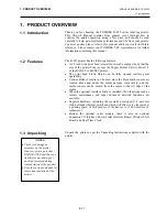
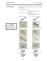
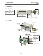
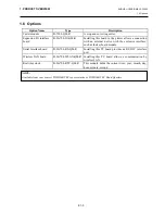
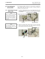
The Toshiba B-852 Advance is a high-performance barcode label printer designed for professional use. With its advanced features and durable construction, it guarantees fast and accurate printing. For convenience, a comprehensive Specification Sheet manual is available for free download from our website, making it easy to set up and utilize this exceptional product.
Share
Download


Reviews:
No comments
Related manuals for B-852 Advance

CanoScan LiDE 120
Brand: Canon Pages: 2

10
Brand: Accu-Sort Pages: 102

2604
Brand: Baracoda Pages: 9

5800
Brand: Youjie Pages: 52

3300
Brand: Youjie Pages: 16

SC1
Brand: Olympus Pages: 2

2020
Brand: Hand Held Products Pages: 248

4800p
Brand: Hand Held Products Pages: 20

TL-120
Brand: Tanca Pages: 22

2008
Brand: JARLTECH Pages: 59

TC1200
Brand: Datalogic Pages: 160

Charge Analyzer 711
Brand: 3M Pages: 26

SC550
Brand: 3nStar Pages: 51

AXIOM
Brand: Accu-Sort Pages: 2

Star
Brand: Datalogic Pages: 5

BaracodaPencil
Brand: HANTZ + PARTNER Pages: 2

Pencil 2
Brand: Baracoda Pages: 2

BCM 2604
Brand: Baracoda Pages: 9


