Toshiba Advanced Port Replicator III, User Manual
The Toshiba Advanced Port Replicator III is a versatile docking station that enhances work productivity. With this product, you can effortlessly connect your devices and expand your workstation. Get the most out of your device by downloading the user manual for free from manualshive.com to easily understand its functionality and features.
Share
Download


Reviews:
No comments
Related manuals for Advanced Port Replicator III

Toughbook CF-F8EWDZZAM
Brand: Panasonic Pages: 20

Toughbook CF-T7BWATAAM
Brand: Panasonic Pages: 12

M460
Brand: Gateway Pages: 4

Chill Mat
Brand: Targus Pages: 2

Chill Mat
Brand: Targus Pages: 4

PECOS Universal
Brand: Speed Link Pages: 4

MicroSaver 2.0
Brand: Kensington Pages: 4

MT6350
Brand: media-tech Pages: 13

BUNDLES S16 OPTICAL MOUSE WIRED
Brand: PORT DESIGNS Pages: 1

LUPAUSL13E
Brand: Logik Pages: 52

SIERRA WIRELESS 250U 4G/3G LAPTOP CARD
Brand: Time Warner Cable Pages: 5

DA-71108
Brand: Digitus Pages: 9

Fieldmate Series
Brand: InfoCase Pages: 4
IN-CRKTCLHY
Brand: Hypertec Pages: 1
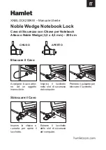
XNBLOCK200KW
Brand: Hamlet Pages: 2
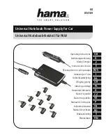
39726
Brand: Hama Pages: 22

TRI-SCREEN 2
Brand: Xebec Pages: 15
Dock II
Brand: IBM Pages: 170


