Toshiba 48-1250 A, Instruction Manual
The Toshiba 48-1250 A is a high-quality electronic device that guarantees exceptional performance for your daily needs. To ensure seamless utilization, make sure to read its comprehensive Instruction Manual. Easily accessible for free download at manualshive.com, the manual provides step-by-step instructions, empowering you with complete control over your product.
Share
Download


Reviews:
No comments
Related manuals for 48-1250 A

575
Brand: Dapper Lighting Pages: 2

2020
Brand: Accel Pages: 2

Titanium Series
Brand: Fass Pages: 13

Raptor
Brand: Yamaha Pages: 2

Porsche 911 Turbo S Wheel
Brand: FANATEC Pages: 9

2008 Liberty
Brand: Jeep Pages: 6

Yamaha Rhino 660
Brand: Yamaha Pages: 3

10-8002-C11998B
Brand: Saleen Pages: 12

WingMan
Brand: Code 3 Pages: 8

For 1985-1992 GM Cars and Trucks 17933
Brand: Edelbrock Pages: 4

6883
Brand: Edelbrock Pages: 2

AX-AM-AU92
Brand: Axxess Pages: 8

66002
Brand: Edelbrock Pages: 2

Chevrolet 5783
Brand: Edelbrock Pages: 1

EM-2201
Brand: Audiovox Pages: 1
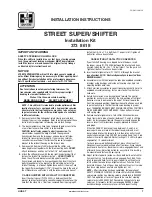
STREET SUPER SHIFTER
Brand: HURST Pages: 2

Ride-Rite Air Helper Springs 2173
Brand: Firestone Pages: 4

65932
Brand: Edelbrock Pages: 2


