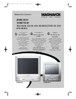
background image

SERVICE MANUAL

14-inch LCD TV/DVD

COMBINATION

DOCUMENT CREATED IN JAPAN, January, 2006

GREEN

14DLV75

FILE NO. 810-200514GR

The above models are classified as either green products (*1) or non-green products. The green products

are indicated by underlined serial numbers. This Service Manual describes replacement parts for the

green products.  When repairing these green product(s), use the part(s) described in this manual and

lead-free solder (*2).

Use this Service Manual in conjunction with the original Service Manual (810-200514) for 14DLV75.

For (*1) and (*2), see the next page.

Summary of Contents for 14DLV75

Page 1: ...or non green products The green products are indicated by underlined serial numbers This Service Manual describes replacement parts for the green products When repairing these green product s use the part s described in this manual and lead free solder 2 Use this Service Manual in conjunction with the original Service Manual 810 200514 for 14DLV75 For 1 and 2 see the next page ...

Page 2: ...ement of parts is not only confined to manufacture The same green parts used in manufacture must also be used as replacement parts 2 LEAD FREE SOLDER This product is manufactured using lead free solder as a part of a movement within the consumer products industry at large to be environmentally responsible Lead free solder must be used in the servicing and repair of this product WARNING This produc...

Page 3: ...FUNCTION STEP NO Change of LCD PANEL Cause 53 53 CON MAX RF 2 3 Confirmation of Fixed Value Step No Please check if the fixed values of each the adjustment items are set correctly referring below From To 51 49 74 BRI CEN DVD 6A ...

Page 4: ...ESCRIPTION TSB P N CAUSE V2301 09EA114003 LCD T140VN01 AE006840 09EA114004 LCD T140VN01 AE008210 Change of LCD PANEL All parts are not interchangeable between version ELECTRICAL REPLACEMENT PARTS LIST MFR S VERSION A MFR S VERSION B REF NO ...

Page 5: ...752WSA0455 SHIELD JACK TUNER 107 AE004525 752WSA0417 SHIELD JACK 109 AE004527 761WSA0167 ANGLE SPEAKER 110 AE006811 771WPB0039 PLATE JACK TUNER 111 AE004529 752WSA0424 SHIELD DVD 112 AE004530 761WSA0160 COVER LCD 113 AE005371 771WPB0022 PLATE JACK 114 AE005372 771WPB0026 PLATE JACK SIDE 115 AE005122 726000A073 SHEET CAUTION 116 AE004533 761WSA0162 ANGLE BACK 117 AE004534 702WPB0044 COVER HINGE 118...

Page 6: ...147 AE001852 8965TS1010 CUSHION 65TS10 10 10 10 25 148 AE005385 8965TS1015 CUSHION 65TS10 5 10 5 15 149 AE005386 8965TS2020 CUSHION 65TS10 5 20 20 15 12 150 AE007006 7230007942 SHEET BARCODE 151 AE007852 J5N00629A INFORMATION SHEET CND 152 AE006819 795WHA0024 PAD FOAM 201 AE003528 8110630A0U SCREW TAP TITE P BRAZIER 3 10 CH 202 AE003529 811063080U SCREW TAP TITE P BRAZIER 3 8 CH 203 AE004849 81092...

Page 7: ... 92P100064A STOPPER DISC 621 AE004572 92P200011A RUBBER ROLLER 622 AE004573 92P300010A SPRING GUIDE ARM 623 AE004574 92P300011A SPRING LEVER DISC L 624 AE004575 92P300012A SPRING LINK 625 AE004576 92P300013A SPRING STOPPER 626 AE004577 92P000006A BRACKET LOADING MOTOR 627 AE004578 92P100066A WORM LOADING 628 AE004579 92P100051A HOLDER TRAVERSE UNIT 629 AE004580 92P100061A ROD TRAVERSE UNIT 630 AE0...

Page 8: ...002220 DIODE SILICON DAN222_TL D8508 BZ410086 DD7R0S3550 DIODE SILICON 1SS355 TE 17 D8509 BZ410086 DD7R0S3550 DIODE SILICON 1SS355 TE 17 D8510 BZ410086 DD7R0S3550 DIODE SILICON 1SS355 TE 17 ICS IC101 AE006852 I55D06080B IC OEC6080B IC103 BZ611122 I9UF032450 IC PST3245NR IC199 AE008280 S5N011CE01 MEMORY DATA BR24L08F WE2 IC601 AD301927 I0UF015040 IC MM1504XNRE IC701 AE001295 I0QJ045800 IC NJM4580M ...

Page 9: ...SB1132T100 Q R Q3002 BZ510020 TNYJB05001 COMPOUND TRANSISTOR DTC114EKAT146 Q3003 BZ510109 TCAA3875SY TRANSISTOR SILICON KTC3875S_Y_RTK Q3004 BZ510108 TAAA1504SY TRANSISTOR SILICON KTA1504S_Y_RTK Q3005 BZ510109 TCAA3875SY TRANSISTOR SILICON KTC3875S_Y_RTK Q3006 BZ510108 TAAA1504SY TRANSISTOR SILICON KTA1504S_Y_RTK Q3007 AE004663 TJ5M081090 FET TPC8109 T2LORION_Q Q3008 AE004663 TJ5M081090 FET TPC810...

Page 10: ...SWITCH TACT EVQ21505R SW2208 BZ612010 0504101T34 SWITCH TACT EVQ21505R SW2209 BZ612010 0504101T34 SWITCH TACT EVQ21505R SW2251 BZ612010 0504101T34 SWITCH TACT EVQ21505R SW2252 BZ612010 0504101T34 SWITCH TACT EVQ21505R SW2253 BZ612010 0504101T34 SWITCH TACT EVQ21505R SW2254 BZ612010 0504101T34 SWITCH TACT EVQ21505R SW2255 BZ612010 0504101T34 SWITCH TACT EVQ21505R P C BOARD ASSEMBLIES PCB130 AE00827...

Page 11: ...OR PCB SIDE A2001WV2 5P CP2301 AE006524 069EV93030 CONNECTOR PCB SIDE 00_6232_009_006_800 CP2302 AE006525 069EVC3030 CONNECTOR PCB SIDE 00_6232_012_006_800 CP2601 AE008279 069GYOT02G CONNECTOR PCB SIDE 09 5000 024 001 002 CP3803 AD301796 069S280629 CONNECTOR PCB SIDE A2001WV2 8P CP3804 AD301998 069S240629 CONNECTOR PCB SIDE A2001WV2 4P CP3805 BZ614242 069S260629 CONNECTOR PCB SIDE A2001WV2 6P CP70...

Page 12: ...TOSHIBA CORPORATION 1 1 SHIBAURA 1 CHOME MINATO KU TOKYO 105 8001 JAPAN ...

Page 13: ...SERVICE MANUAL 14 inch LCD TV DVD COMBINATION DOCUMENT CREATED IN JAPAN February 2005 14DLV75 FILE NO 810 200514 ...

Page 14: ...liance with the FCC Federal Communications Commission Rules could void the user s authority to operate this equipment WARNING Handling the cord on this product or cords associated with accessories sold with this product will expose you to lead a chemical known to the State of California to cause birth defects or other reproductive harm Wash hands after handling IMPORTANT SAFEGUARDS RISK OF ELECTRI...

Page 15: ...www eiae org 6 Introduction Notes on moisture condensation Moisture condensation damages the unit Please read the following carefully Moisture condensation occurs for example when you pour a cold drink into a glass on a warm day Drops of water form on the outside of the glass In the same way moisture may condense on the optical pick up lens inside this unit one of the most crucial internal parts o...

Page 16: ... playback will not be allowed by the player In this case the unit will display a message on screen Some DVDs that have no region code label may still be subject to area restrictions and therefore not playable On Video CDs This DVD supports Video CDs equipped with the PBC Version 2 0 function PBC is the abbreviation of Playback Control You can enjoy two playback variations depending on types of dis...

Page 17: ...0 ohm twin lead wire to the combiner not supplied Connect the VHF 300 ohm twin lead wire to the 300 75 ohm matching transformer Attachthetransformertothecombiner then attach the combiner to the antenna jack on the back of the TV DVD Connect the VHF 75 ohm cable and UHF 300 ohm twin lead wire to the combiner not supplied Attach the combiner to the antenna jack on the back of the TV DVD Combination ...

Page 18: ... Front speaker Rear speaker Sub woofer Center speaker Signal flow Dolby Digital Dolby Digital is the surround sound technology used in theaters showing the latest movies and is now available to reproduce this realistic effect in the home You can enjoy motion picture and live concert DVD video discs encoded via the Dolby Digital recording system with this dynamic realistic sound by connecting the T...

Page 19: ...r down to the next channel set into memory skipping over unwanted channels Before selecting channels they must be programmed into the TV DVD s memory In addition to normal VHF and UHF channels this TV DVD can receive up to 113 Cable TV channels To use this TV DVD with an antenna set the TV CABLE selection to the TV position When shipped from the factory this selection is in the CABLE position 0 9 ...

Page 20: ...ning will display text on the screen for hearing impaired viewers or it will translate and display text in another language Notes When selecting closed captions the captioning will be delayed approximately 10 seconds If no caption signal is received no captions will appear but the television will remain in the caption mode Misspellings or unusual characters may occasionally appear during closed ca...

Page 21: ...eo sound from the left and right speakers When mono broadcasting is received no indication is displayed If the broadcast signal is not strong enough or clear stereo sound is not available press AUDIO to change to mono sound The noise may be eliminated Press it again to return to the stereo sound Listening to SAP Second Audio Program When the TV is turned on or a channel selection is made make cert...

Page 22: ...ay appear at the upper left of the screen This symbol means either the feature you tried is not available on the disc or the TV DVD cannot access the feature at this time This does not indicate a problem with the TV DVD Note DVD VCD CD DVD VCD CD Playing in slow motion Locating a chapter or track DVD VCD DVD VCD REV PAUSE SKIP FWD PLAY SLOW 34 Advanced playback Press to view a different part of th...

Page 23: ...e menu When you playback these DVDs you can select the subtitle language and sound track language etc using the menu 1 Press ENTER The menu continues to another screen Repeat steps 2 and 3 to set the item completely 3 2 Changing angles Title selection DVD menu Note Depending on the DVD you may not be able to resume playback from the scene point when you pressed the DVD MENU button Press to select ...

Page 24: ... Press ENTER The selected file starts playing back 4 Press STOP to end playback The unit records the stopped point appears on the screen Press PLAY to resume playback from the scene point If you press STOP again or unload the disc the unit will clear the stopped point About file menu Notes The picture menu is displayed when the FUJICOLOR CD or the Kodak Picture CD are played To display the file me...

Page 25: ... the remote control PASSWORD CLEAR ap pears on the screen 5 Enter a new password again On Loud sound such as explosion or similar is toned down slightly when played back This makes it suitable for when it is connected to a stereo Off It plays back at the recording level on the disc Notes This function works only during playback of Dolby Digital recorded discs The level of Dynamic Range Reduction m...

Page 26: ... path of the beam The batteries are weak Replace the batteries Check the batteries are inserted correctly The unit or remote operation key is not functioning Turn off the unit and unplug the AC power cord for several min utes then replug it 31 7 8 31 33 18 44 13 Angle cannot be changed Multi angles are not recorded on the DVD disc The function is prohibited with the unit or the disc appears on the...

Page 27: ...es extend only to defects in materials or workmanship as limited above and do not extend to any LCD TV DVD Combination or parts that have been lost or discarded by you or to damage to the LCD TV DVD Combination or parts caused by fires misuse accident Acts of God such as lightning or fluctuations in electric power improper installation improper maintenance or use in violation of instructions furni...

Page 28: ...quired Marking The rating sheet and the safety caution are on the rear of the unit CERTIFICATION COMPLIES WITH FDA RADIATION PERFORMANCE STANDARDS 21 CFR SUBCHAPTER J PREPARATION OF SERVICING The laser diode used for a pickup head may be destroyed with external static electricity Moreover even if it is operating normally after repair when static electricity discharge is received at the time of rep...

Page 29: ...ation transformer for this check Use a leakage current tester Fig 1 or a metering system which complies with Underwriters Laboratories UL 1409 Measure for current from all exposed metal parts of the cabinet to a known earth ground particularly any exposed metal part having a return path to the chassis Any current measured must not exceed 0 5mA Any measurement not within the limits outlined above a...

Page 30: ...al power company For units intended to operate from battery power or other sources refer to the operating instructions GROUNDING OR POLARIZATION This unit is equipped with a polarized alternating current line plug a plug having one blade wider than the other This plug will fit into the power outlet only one way This is a safety feature If you are unable to insert the plug fully into the outlet try...

Page 31: ... equipment turn off the power and unplug all of the equipment from the wall outlet Failure to do so may cause an electric shock and serious personal injury Read the owner s manual of the other equipment carefully and follow the instructions when making any connections SOUND VOLUME Reduce the volume to the minimum level before you turn on the product Otherwise sudden high volume sound may cause hea...

Page 32: ...ICAL CODE ANTENNA DISCHARGE UNIT NEC SECTION 810 20 ANTENNA LEAD IN WIRE GROUNDING CONDUCTORS NEC SECTION 810 21 GROUND CLAMPS POWER SERVICE GROUNDING ELECTRODE SYSTEM NEC ART 250 PART H GROUND CLAMP ELECTRIC SERVICE EQUIPMENT NEC NATIONAL ELECTRICAL CODE S2898A ...

Page 33: ...e soldering on the short circuit position after the connection of Pick Up PCB and DVD PCB connector Fig 1 Pick Up PCB Before your operation please read PREPARATION OF SERVICING Use the Lead Free solder Manual soldering conditions Soldering temperature 320 20 C Soldering time Within 3 seconds Soldering combination Sn 3 0Ag 0 5Cu When Soldering Removing of solder use the draw in equipment over the P...

Page 34: ...CLEAR will appear The 4 digit password has now been cleared 1 2 3 4 5 6 Tray cannot be opened by setting the Tray Lock please follow the steps below Turn Unit ON Set the DVD to the Stop Mode Press and hold the STOP key on the front panel Simultaneously press and hold the 9 key on the remote control unit Hold both keys for more than 3 seconds The On Screen Display message will appear The Tray Lock ...

Page 35: ...ACK LIGHT OPERATION START SW END SW SCHEMATIC DIAGRAMS TUNER STEREO MICON SOUND AMP IN OUT POWER SIDE JACK REMOCON DECODER SCALER1 SCALER2 LVDS MPEG MICON DSP MEMORY2 RF AMP AUDIO VIDEO MOTOR DRIVE REGULATOR2 INVERTER OPERATION START SW END SW INTERCONNECTION DIAGRAM WAVEFORMS MECHANICAL EXPLODED VIEW DVD DECK EXPLODED VIEW MECHANICAL REPLACEMENT PARTS LIST DVD DECK REPLACEMENT PARTS LIST ELECTRIC...

Page 36: ...ation US W CABLE CH Coverage 2 69 4A A 5 A 1 A I J W W 1 W 84 Intermediate Picture FP 45 75MHz Frequency Sound FS 41 25MHz FP FS 4 50MHz Preset CH No Stereo Dual TV Sound US Stereo Tuner Sound Muting Yes G 4 Signal Video Signal Input Level 1 V p p 75 ohm Output Level S N Ratio Weighted Horizontal Resolution at DVD Mode RGB Signal Output Level Audio Signal Input Level 8 0dBm 50k ohm Output Level Di...

Page 37: ...Dimmer No CH Tuning Yes TV CABLE Yes Add Delete Yes Auto CH Memory Yes V Chip Yes Language Yes Clock Set No Pin Code Registration No Sound System No AV2 Output Source No Control Level Yes Volume Yes Brightness Yes Contrast Yes Color Yes Tint Yes Sharpness Yes Bass Yes Treble Yes Balance Yes Stereo Yes Pin Code No CH AV DVD Yes Component Yes Hotel Lock No CH Label No Sleep Timer Yes Caption Text Ye...

Page 38: ...es Prohibit Mark Yes Step Yes Skip Yes Skip Yes Random Yes CD VIDEO CD MP3 WMA JPEG Repeat Yes Slow Yes Slow Yes Search Yes Search Yes Jump Yes Resume Yes Title No Yes Chapter No Yes Track No Yes Time Yes Sub Title No Yes Angle No Yes Vocal On Off Yes Audio No Yes Audio Stereo L R Yes VIDEO CD Zoom Yes Marker No No Program Play Back Yes CD VIDEO CD MP3 WMA JPEG Surround On Off No Screen Saver No M...

Page 39: ...9 Yes 0 Yes Play Yes Stop Yes Search Yes Search Yes Skip Yes Skip Yes Slow Yes Slow Yes Pause Still Step Yes Recall Yes TV DVD Yes Cancel Yes Audio Select Yes Angle Yes Subtitle Yes Top Menu Yes Setup Menu Yes DVD Menu Yes Return Yes Up CH Up Yes Down CH Down Yes Vol Down Yes Vol Up Yes Left Yes Right Yes Enter Yes Play Mode Yes Closed Caption Yes Input Select Yes Repeat A B Yes Zoom Quick View Ye...

Page 40: ...al Out Dolby Digital Yes MPEG Yes PCM Yes DTS Yes Down Mix Out Dolby Digital Yes DTS No 3D Surround No Screen Saver No Audio DAC 192kHz 24bit G 15 Accessories Owner s Manual Language English French w Guarantee Card Yes Remote Control Unit Yes Rod Antenna No Poles Terminal Loop Antenna No Terminal U V Mixer No DC Car Cord Center No Guarantee Card No Warning Sheet No Circuit Diagram No Antenna Chang...

Page 41: ...nd Approx W x D x H mm 437 x 85 5 x 289 G 18 Weight Net Approx 5 5kg 12 1 lbs Net w o Handle Stand Approx 4 5kg 9 9 lbs Gross Approx 7 5kg 16 5 lbs G 19 Carton Master Carton No Content Sets Material Dimensions W x D x H mm Description of Origin Gift Box Material Single White W Color Photo Label No Dimensions W x D x H mm 518x411x263 Description of Origin Yes Drop Test Natural Dropping At 1 Corner ...

Page 42: ...et 1 3 BACK ANGLE Refer to Fig 1 3 1 2 3 4 5 6 Remove the 3 screws 1 Remove the screw 2 Remove the 2 screws 1 Remove the Jack Plate and Jack Shield in the direction of arrow A Remove the 3 screws 4 Remove the Back Angle in the direction of arrow B Fig 1 3 1 C 4 1 2 3 3 A Jack Plate Jack Shield A Jack Plate Jack Shield 4 Back Angle B 1 4 4 1 4 DVD PCB Refer to Fig 1 4 1 2 3 4 5 Short circuit the po...

Page 43: ...e 320 20 C Soldering time Within 3 seconds Soldering combination Sn 3 0Ag 0 5Cu When Soldering Removing of solder use the drawing equipment over the Pick Up Unit to keep the Flux smoke away from it When installing the DVD Deck remove all the soldering on the short circuit position after the connection of Pick Up PCB and DVD PCB connector 1 2 3 4 5 1 LCD PCB 1 1 1 1 1 1 7 LCD PCB Refer to Fig 1 7 1...

Page 44: ...8 1 Side Jack PCB 1 1 Jack Plate Jack Shield 1 9 1 2 3 4 5 6 7 8 Remove the 2 screws 1 Remove the Cover Shield in the direction of arrow A Remove the 6 screws 2 Remove the LCD Block in the direction of arrow B Remove the 2 screws 3 Remove the Operation PCB in the direction of arrow C Remove the 4 screws 4 Remove the LCD Panel in the direction of arrow D Fig 1 9 1 1 LCD Cover 2 LCD Panel 3 B Front ...

Page 45: ... 1 Motor Loading Worm Start SW PCB Ass y 2 2 3 4 4 5 5 End SW PCB Ass y 29 7 0 1mm Safety surface for pressing of the insert Motor Loading Worm Fig 2 1 C Start SW PCB Ass y End SW PCB Ass y Motor Red Black Red Black 2 2 Remove the screw 1 Remove the Traverse Unit Rod Remove the 2 screws 3 Unlock the 2 supports 4 and remove the CD Deck Block Remove the 2 screws 5 Unlock the 2 supports 6 and remove ...

Page 46: ... 1 In case of the Upper Roller installation install correctly as Fig 2 4 B Fig 2 4 B OK NG Upper Roller Upper Roller Roller Gear Roller Gear Rack Loading Guide Arm Spring Rack Gear Mid Rack Gear LINK R ASS Y LINK L LINK MID LINK SPRING Refer to Fig 2 6 Remove the screw 1 Remove the Link Spring Unlock the support 2 and remove the Link L Unlock the support 3 and remove the Link Mid Remove the screw ...

Page 47: ...2 8 A Unlock the support 1 and remove the Clamper Ass y Unlock the support 2 and remove the Disc Guide Arm Unlock the support 3 and remove the Disc R Lever 1 2 3 Clamper Ass y 1 3 2 Disc Guide Arm Disc R Lever NOTE 1 When installing the Clamper Ass y check if the Clamper Ass y is locked correctly as Fig 2 8 B ...

Page 48: ...ring the IC leads completely Fig 3 2 Blower type IC desoldering machine IC 3 When IC starts moving back and forth easily after desoldering completely pickup the corner of the IC using a tweezers and remove the IC by moving with the IC desoldering machine Refer to Fig 3 3 NOTE Some ICs on the PCB are affixed with glue so be careful not to break or damage the foil of each IC leads or solder lands un...

Page 49: ...eld Wire Refer to Fig 3 7 NOTE Do not absorb the solder to excess Fig 3 7 Soldering Iron IC Braided Shield Wire 4 When bridge soldering between terminals and or the soldering amount are not enough resolder using a Thin tip Soldering Iron Refer to Fig 3 8 Fig 3 8 Thin tip Soldering Iron IC 5 Finally confirm the soldering status on four sides of the IC using a magnifying glass Confirm that no abnorm...

Page 50: ...ote control for more than 1 second After the confirmation of using hours turn off the power Initial setting content of MEMORY IC POWER ON total hours 16 x 16 x 16 x thousands digit value 16 x 16 x hundreds digit value 16 x tens digit value ones digit value FIG 1 ADDRESS DATA INIT 00 25 LCD ON 0010 Tray cannot be opened Refer to the TRAY LOCK NOTE No indications on the screen when the Tray Lock is ...

Page 51: ...p Date Logo screen will appear Unplug the AC cord then plug it in After the write set to the initializing of shipping Turn on the power and set the DVD mode Press both VOL DOWN button on the set and Channel button 4 on the remote control for more than 1 second The INITIALIZE 5 COMPLETE will appear on the screen Then unplug the AC cord and plug it in CHECK FOR THE FIRMWARE VERSION Turn on the power...

Page 52: ...through the ADDRESS until required ADDRESS to be changed is reached Press ENTER to select DATA When DATA is selected it will blink Again step through the DATA using VOL UP DOWN button until required DATA value has been selected Pressing ENTER will take you back to ADDRESS for further selection if necessary Repeat steps 4 to 7 until all data has been checked When satisfied correct DATA has been ent...

Page 53: ...G ELECTRICAL ADJUSTMENTS Prepare the following measurement tools for electrical adjustments 1 Oscilloscope 2 AC Voltmeter 3 Pattern Generator 4 Multi Sound Signal Generator On Screen Display Adjustment Set the VOLUME to minimum Press the VOL DOWN button on the set and the Channel button 9 on the remote control for more than 1 second to appear the adjustment mode on the screen as shown in Fig 1 1 1...

Page 54: ...7F 00 1E 35 00 0 06 06 00 00 2A 79 7C 7F 3F 3F 0 0 0 67 53 3F 44 45 3F 79 7D 80 3F 3F 0 0 0 5A 4D 3F 47 49 4C 79 7B 7C 3F 3F 0 0 0 6D 53 3F 4E 48 35 74 90 30 30 51 10 8C F0 00 46 7F 00 1E 35 00 0 06 06 00 00 2A 79 7C 7F 3F 3F 0 0 0 67 53 3F 44 45 3F 79 7D 80 3F 3F 0 0 0 5A 4D 3F 47 49 4C 79 7B 7C 3F 3F 0 0 0 6D 53 3F 4E 48 35 74 90 30 30 51 10 8A F0 00 4E 7F 00 1A 35 00 0 00 00 00 00 2A 79 7C 7F 3...

Page 55: ...PCB CD701 CD2601 DVD PCB DVD DECK SPEAKER LCD PANEL CD802 J701 CP3803 J3801 CP3804 CP701 J706 CP1001 CP705 CP101 CP103 CP102 CP104 CP3805 J702 J703J704 J708J707J705 TU001 OS2201 CD2201 CD101 CP7002 CP7003 CP7004 CP7005 CP801 CP805 CP806 CD804 CD807 CP2302 CP2301 CP2601 CD501 AV PCB BACK LIGHT PCB CD7001 CD705 J1001 J792 J791 J790 CD102 CD103 ...

Page 56: ... 201 201 201 119 123 201 201 122 120 102C 121 205 205 205 205 203 117 203 102D 201 201 201 101D 101C 101 102B 102E 102F 102J 102I 102N 102M 102L 102K 102G 102H 102P 102O 201 201 201 109 109 109 109 108 102Q 201 201 201 201 201 201 PCB350 BACK LIGHT PCB ASS Y 137 201 201 124 103 118 139 139 205 202 202 ...

Page 57: ... 114 PCBD90 SIDE JACK PCB ASS Y 141 204 104 PCB270 OPERATION 1 PCB ASS Y 204 204 201 201 204 204 204 204 204 204 140 116 115 138 148 147 204 204 204 204 204 204 204 201 201 201 201 201 204 204 204 A PCB340 LCD PCB ASS Y MECHANICAL EXPLODED VIEW I1 2 204 204 204 146 144 145 143 204 111 136 PCB130 DVD PCB ASS Y 149 125 V2301 ...

Page 58: ...MECHANICAL EXPLODED VIEW PACKING DIAGRAM 132 133 134 135 151 127 128 126 I1 3 131 BL001 AD001 TM101 CD503 BT001 BT002 129 130 150 152 ...

Page 59: ... 612 623 619 621 611 703 703 604 617 AA AA AA AA DVD DECK EXPLODED VIEW TOP VIEW I2 1 Applying positions AA for the grease are displayed for this section Check if the correct grease is applied for each position NOTE CLASS GREASE MARK AA ...

Page 60: ... SW3 CP2 628 630 630 630 701 630 701 DK1 701 701 PCB590 END SW PCB ASS Y SW4 702 AA AA AA AA AA AA AA AA AA AA 702 M2301 627 702 626 705 703 624 615 614 704 602 AA Applying positions AA for the grease are displayed for this section Check if the correct grease is applied for each position NOTE CLASS GREASE MARK AA ...

Page 61: ...LD JACK TUNER 107 AE004525 752WSA0417 SHIELD JACK 108 AE007005 7230007951 SHEET DVD 109 AE004527 761WSA0167 ANGLE SPEAKER 110 AE006811 771WPB0039 PLATE JACK TUNER 111 AE004529 752WSA0424 SHIELD DVD 112 AE004530 761WSA0160 COVER LCD 113 AE005371 771WPB0022 PLATE JACK 114 AE005372 771WPB0026 PLATE JACK SIDE 115 AE005122 726000A073 SHEET CAUTION 116 AE004533 761WSA0162 ANGLE BACK 117 AE004534 702WPB0...

Page 62: ...LD FFC 147 AE001852 8965TS1010 CUSHION 65TS10 10 10x20x25 148 AE005385 8965TS1015 CUSHION 65TS10 5 15x20x16 149 AE005386 8965TS2020 CUSHION 65TS10 5 20 20x15x12 150 AE007006 7230007942 SHEET BARCODE 151 AE005543 J2E50729A INFORMATION SHEET 152 AE006819 795WHA0024 PAD FOAM 201 AE003528 8110630A0U SCREW TAP TITE P BRAZIER 3x10 202 AE003529 811063080U SCREW TAP TITE P BRAZIER 3x8 203 AE004849 8109230...

Page 63: ...571 92P100064A STOPPER DISC 621 AE004572 92P200011A RUBBER ROLLER 622 AE004573 92P300010A SPRING GUIDE ARM 623 AE004574 92P300011A SPRING LEVER DISC L 624 AE004575 92P300012A SPRING LINK 625 AE004576 92P300013A SPRING STOPPER 626 AE004577 92P000006A BRACKET LOADING MOTOR 627 AE004578 92P100066A WORM LOADING 628 AE004579 92P100051A HOLDER TRAVERSE UNIT 629 AE004580 92P100061A ROD TRAVERSE UNIT 630 ...

Page 64: ...3 AD302345 R803R9472J RC 4 7K OHM 1 16W R164 AD302345 R803R9472J RC 4 7K OHM 1 16W R601 AE000849 R803R9152J RC 1 5K OHM 1 16W R602 AE000849 R803R9152J RC 1 5K OHM 1 16W R603 AE000849 R803R9152J RC 1 5K OHM 1 16W R604 AE000849 R803R9152J RC 1 5K OHM 1 16W R605 AE002149 R803R9274J RC 270K OHM 1 16W R606 AE000849 R803R9152J RC 1 5K OHM 1 16W R607 AE001781 R803R9101J RC 100 OHM 1 16W R608 AE001787 R80...

Page 65: ...R764 AE001283 R803R9470J RC 47 OHM 1 16W R765 AE001283 R803R9470J RC 47 OHM 1 16W R769 AE001887 R803R9105J RC 1M OHM 1 16W R770 AE001887 R803R9105J RC 1M OHM 1 16W R772 AE001803 R803R9750J RC 75 OHM 1 16W R773 AE001803 R803R9750J RC 75 OHM 1 16W R774 AE001803 R803R9750J RC 75 OHM 1 16W R775 AE001803 R803R9750J RC 75 OHM 1 16W R776 AE001803 R803R9750J RC 75 OHM 1 16W R791 AE001803 R803R9750J RC 75 ...

Page 66: ...E001784 R803R9103J RC 10K OHM 1 16W R1048 AE001799 R803R9562J RC 5 6K OHM 1 16W R1049 AE001784 R803R9103J RC 10K OHM 1 16W R1050 AE003270 R3X28B2R7J R METAL OXIDE 2 7 OHM 3W R1051 AE001784 R803R9103J RC 10K OHM 1 16W R1053 AE000037 R3X28B3R9J R METAL 3 9 OHM 3W R2202 AD301301 R002T4152J RC 1 5K OHM 1 4W R2204 BZ210119 R002T4102J RC 1K OHM 1 4W R2206 AE000362 R002T4821J RC 820 OHM 1 4W R2209 AE0021...

Page 67: ...2626 AE002151 R803R9391J RC 390 OHM 1 16W R2633 AD302345 R803R9472J RC 4 7K OHM 1 16W R2634 AE001887 R803R9105J RC 1M OHM 1 16W R2635 AE001887 R803R9105J RC 1M OHM 1 16W R2643 AE001783 R803R9102J RC 1K OHM 1 16W R2644 AE001790 R803R9222J RC 2 2K OHM 1 16W R2645 AE001783 R803R9102J RC 1K OHM 1 16W R2646 AE001790 R803R9222J RC 2 2K OHM 1 16W R2647 AD302345 R803R9472J RC 4 7K OHM 1 16W R2648 AE000848...

Page 68: ...0 R803R9221J RC 220 OHM 1 16W R4031 AD302345 R803R9472J RC 4 7K OHM 1 16W R4032 AE001891 R803R9223J RC 22K OHM 1 16W R4033 AE001793 R803R92R2J RC 2 2 OHM 1 16W R4034 AE001793 R803R92R2J RC 2 2 OHM 1 16W R4035 AD302345 R803R9472J RC 4 7K OHM 1 16W R4036 AD302345 R803R9472J RC 4 7K OHM 1 16W R4037 AD302345 R803R9472J RC 4 7K OHM 1 16W R4038 AD302345 R803R9472J RC 4 7K OHM 1 16W R4039 AD302345 R803R9...

Page 69: ...R801R7474J RC 470K OHM 1 10W R7046 79091325 R801R7474J RC 470K OHM 1 10W R7047 79091325 R801R7474J RC 470K OHM 1 10W R7048 79091325 R801R7474J RC 470K OHM 1 10W R7049 BZ210263 R801R7562F RC 5 6K OHM 1 10W R7051 79091325 R801R7474J RC 470K OHM 1 10W R7052 79091325 R801R7474J RC 470K OHM 1 10W R7053 79091325 R801R7474J RC 470K OHM 1 10W R7054 79091325 R801R7474J RC 470K OHM 1 10W R7055 79091325 R801...

Page 70: ...412J CC 100 PF 50V CH C135 79091065 CS0PCH4N1J CC 39 PF 50V CH C601 AE005074 E61UM5R47D CE 0 47 UF 50V C604 AE005074 E61UM5R47D CE 0 47 UF 50V C606 AE001726 CS0PB0414K CC 0 01 UF 50V B C607 AE001726 CS0PB0414K CC 0 01 UF 50V B C608 AE001726 CS0PB0414K CC 0 01 UF 50V B C609 AE005076 E61UMQ331D CE 330 UF 4V C610 AE001730 CS0PCH4E2J CC 150 PF 50V CH C611 AE001730 CS0PCH4E2J CC 150 PF 50V CH C613 AE00...

Page 71: ...CE 100 UF 16V C708 AE001725 CS0PB0413K CC 0 001 UF 50V B C709 AE002126 CS0PB04E4K CC 0 015 UF 50V B C710 AE001544 E50HU3100M CE 10 UF 25 V C711 AD301535 E02LU2101M CE 100 UF 16V C712 AE001544 E50HU3100M CE 10 UF 25 V C713 BZ110074 E50HU5010M CE 1 UF 50V C716 AE001737 CS0PF0N16Z CC 1 UF 10V F C717 AE001737 CS0PF0N16Z CC 1 UF 10V F C718 AE000332 E00NU2100M CE 10 UF 16 V C719 AE001544 E50HU3100M CE 1...

Page 72: ... B C831 AE001726 CS0PB0414K CC 0 01 UF 50V B C832 AE002124 CS0PB0315K CC 0 1 UF 25V B C833 AE002124 CS0PB0315K CC 0 1 UF 25V B C834 AE002124 CS0PB0315K CC 0 1 UF 25V B C835 AE002124 CS0PB0315K CC 0 1 UF 25V B C836 AE002124 CS0PB0315K CC 0 1 UF 25V B C837 AE002124 CS0PB0315K CC 0 1 UF 25V B C838 AE002124 CS0PB0315K CC 0 1 UF 25V B C839 AE002124 CS0PB0315K CC 0 1 UF 25V B C840 AE002124 CS0PB0315K CC...

Page 73: ...V C941 AE001737 CS0PF0N16Z CC 1 UF 10V F C942 AE000838 CS0PB0N16K CC 1 UF 10V B C943 AE001737 CS0PF0N16Z CC 1 UF 10V F C944 AE000838 CS0PB0N16K CC 1 UF 10V B C945 AE002124 CS0PB0315K CC 0 1 UF 25V B C946 AD301535 E02LU2101M CE 100 UF 16V C947 AE002123 CQGTF0416Z CC 1 UF 50V F C948 AE002123 CQGTF0416Z CC 1 UF 50V F C949 AE001737 CS0PF0N16Z CC 1 UF 10V F C950 AE002123 CQGTF0416Z CC 1 UF 50V F C951 A...

Page 74: ...414K CC 0 01 UF 50V B C2205 BZ110150 E50HU0101M CE 100 UF 6 3V C2301 AE002124 CS0PB0315K CC 0 1 UF 25V B C2302 AE001733 CS0PCH4H2J CC 220 PF 50V CH C2303 AE001726 CS0PB0414K CC 0 01 UF 50V B C2304 AE002124 CS0PB0315K CC 0 1 UF 25V B C2305 AE002124 CS0PB0315K CC 0 1 UF 25V B C2306 AE002124 CS0PB0315K CC 0 1 UF 25V B C2307 AE002124 CS0PB0315K CC 0 1 UF 25V B C2308 AE001727 CS0PB04H3K CC 0 0022UF 50V...

Page 75: ...Z CC 0 1 UF 50V F C2643 AE001543 E50HU0470M CE 47 UF 6 3V C2644 AE001543 E50HU0470M CE 47 UF 6 3V C2645 AE001275 CS0PF0415Z CC 0 1 UF 50V F C2646 AE001543 E50HU0470M CE 47 UF 6 3V C2647 AE001275 CS0PF0415Z CC 0 1 UF 50V F C2648 AE000838 CS0PB0N16K CC 1 UF 10V B C2654 AE001726 CS0PB0414K CC 0 01 UF 50V B C2655 AE001726 CS0PB0414K CC 0 01 UF 50V B C3001 AE006849 E61FT3331D CE 330 UF 25V C3002 AE0021...

Page 76: ... AE000336 E02LU1101M CE 100 UF 10V C4012 AE001275 CS0PF0415Z CC 0 1 UF 50V F C4013 AE001275 CS0PF0415Z CC 0 1 UF 50V F C4014 AE001275 CS0PF0415Z CC 0 1 UF 50V F C4016 AE001275 CS0PF0415Z CC 0 1 UF 50V F C4017 AE001275 CS0PF0415Z CC 0 1 UF 50V F C4018 AE001275 CS0PF0415Z CC 0 1 UF 50V F C4019 AE001275 CS0PF0415Z CC 0 1 UF 50V F C4020 AE001275 CS0PF0415Z CC 0 1 UF 50V F C4022 AE001275 CS0PF0415Z CC ...

Page 77: ...0V B C7009 AE000838 CS0PB0N16K CC 1 UF 10V B C7010 AE001725 CS0PB0413K CC 0 001 UF 50V B C7011 AE000838 CS0PB0N16K CC 1 UF 10V B C7012 AE006848 CS0PCH4U2H CC 680 PF 50V CH C7013 AE005068 CS0PB0415K CC 0 1 UF 50V B C7014 AE001726 CS0PB0414K CC 0 01 UF 50V B C7016 AE004234 CS0PB02L5K CC 0 33 UF 16V B C7017 AE000838 CS0PB0N16K CC 1 UF 10V B C7019 AE001725 CS0PB0413K CC 0 001 UF 50V B C7020 AE005068 C...

Page 78: ...99 AE006857 S5N006CE01 MEMORY DATA BR24L08F WE2 IC601 AD301927 I0UF015040 IC MM1504XNRE IC701 AE001295 I0QJ045800 IC NJM4580M TE1 IC702 BZ611139 I0QF02534V IC NJM2534V TE2 IC703 AD301988 I0UF015010 IC MM1501XNRE IC704 AE004651 I0QF025840 IC NJM2584AM TE1 IC801 AE006853 I55M0288B0 IC TC90288BXBG IC802 AE004654 I1KF98D330 IC KIA78D33F IC803 AE004660 IFKJ0LM850 IC DTC34LM85AL IC804 AE006395 I0GF91ZPH...

Page 79: ...3875S_Y_RTK Q3004 BZ510108 TAAA1504SY TRANSISTOR SILICON KTA1504S_Y_RTK Q3005 BZ510109 TCAA3875SY TRANSISTOR SILICON KTC3875S_Y_RTK Q3006 BZ510108 TAAA1504SY TRANSISTOR SILICON KTA1504S_Y_RTK Q3007 AE004663 TJ5M081090 FET TPC8109 T2LORION_Q Q3008 AE004663 TJ5M081090 FET TPC8109 T2LORION_Q Q3801 AE004665 TS3M000044 COMPOUND TRANSISTOR CPH6312 TL E Q3802 BZ510021 TNYJC05001 COMPOUND TRANSISTOR DTC12...

Page 80: ...1T34 SWITCH TACT EVQ21505R SW2204 BZ612010 0504101T34 SWITCH TACT EVQ21505R SW2206 BZ612010 0504101T34 SWITCH TACT EVQ21505R SW2208 BZ612010 0504101T34 SWITCH TACT EVQ21505R SW2209 BZ612010 0504101T34 SWITCH TACT EVQ21505R SW2251 BZ612010 0504101T34 SWITCH TACT EVQ21505R SW2252 BZ612010 0504101T34 SWITCH TACT EVQ21505R SW2253 BZ612010 0504101T34 SWITCH TACT EVQ21505R SW2254 BZ612010 0504101T34 SWI...

Page 81: ...02_800 CD2201 AE005065 06CU252001 CORD CONNECTOR CU252001 CD2601 AE001699 122H0O1902 CORD JUMPER 2H0O1902 CD7001 AE006836 06C3282602 CORD CONNECTOR C3282602 CP1001 AD301045 069S140419 CONNECTOR PCB SIDE A2502WV2 4P CP2201 AD300752 069S250629 CONNECTOR PCB SIDE A2001WV2 5P CP2301 AE006524 069EV93030 CONNECTOR PCB SIDE 00_6232_009_006_800 CP2302 AE006525 069EVC3030 CONNECTOR PCB SIDE 00_6232_012_006...

Page 82: ...RBON RESISTOR CAPACITORS CC CERAMIC CAPACITOR CE ALUMI ELECTROLYTIC CAPACITOR CP POLYESTER CAPACITOR CPP POLYPROPYLENE CAPACITOR CPL PLASTIC CAPACITOR CMP METAL POLYESTER CAPACITOR CMPL METAL PLASTIC CAPACITOR CMPP METAL POLYPROPYLENE CAPACITOR J3 19 ...

Page 83: ...TOSHIBA CORPORATION 1 1 SHIBAURA 1 CHOME MINATO KU TOKYO 105 8001 JAPAN ...

Page 84: ...SERVICE MANUAL 14 inch LCD TV DVD COMBINATION DOCUMENT CREATED IN JAPAN February 2005 14DLV75 FILE NO 810 200514 CIRCUIT DIAGRAMS ...

Page 85: ...E2 A D RFA_SDEN DATA SCLK FNN FNP VBIASS0 S1 D D D E MD MC ML AMCLK ABCLK ASDATAO ALRCLK B U AUDIO R DVD RESET Y V AUDIO L TV BLOCK ZERO TR FO DISC_IN DISC_END SW TXD SPDIF RXD A P CON 6 5V_D B P CON 5V_D C P CON A5V_D D P CON 3 3V_D E P CON 1 8V_D A B C D E F IN SW LDO Stepping Motor REF1 REF2 W V U HW HV HU C C A DISC_IN SW DISC_IN DISC_END SW DISC_IN_SW PSMUTE SBMUTE FOCUS_DAC TRACK_DAC LDM DIS...

Page 86: ...TRANS T7002 CRT 025 INVERTER TRANS T7001 CRT 025 SW CONTROLLER IC7002 TH12 TX OUT 0 3 TX OUT 0 3 TX CLKOUT TX CLKOUT TV BLOCK DIAGRAM FROM DVD PCB DVD_Y DVD_U DVD_V SOUND DECODER IC901 AN5832SA SW IC905 IC906 NJM2534V SW IC903 IC904 MM1501XNRE L R AV2 L R SPIF 134 COAXIAL J701 V V VIDEO_OUT S_IN_Y S_IN_C AV1_V_IN AV1_A_IN_L R AV2_V_IN AV2_A_IN_L R DVD_AUDIO_L R SW IC702 NJM2534V U V CONPONENT Y SW...

Page 87: ...32V P CON 3 3V P CON 3 3V P CON 1 5V SOUND B INVERTER P CON 9V E 5 E 6 POWER BLOCK DIAGRAM P CON 2 5V Q3001 F3001 ADAPTER 12V GND DVD POWER 2CH SW REG CONTROLLER IC3001 BA9743AFV Q3007 FET Q3008 UNREG 12V SW 5V REG IC3003 KIA78D05F 3 3V REG IC3005 KIA78D33F 1 8V REG IC3004 PQ070XZ01ZP 1 8V REG IC3002 PQ070XZ01ZP FET P CON 7V_D P CON 5V_D P CON A5V_D P CON 3 3V_D P CON A3 3V_D P CON 1 8V_D P CON A1...

Page 88: ...R623 R624 C877_1 C842_1 C895 C634 C629 C887 C883 L819 C626 C621 C813 C654 C891 R858 C625 C658 C899 L804 C824 C652 C631 C640 C841 L603 C637 C894 C809 C624 C888 C643 C890 C817 C827 C829 R832 R859 C630 C644 C636 C882 C628 C623 C889 C632 C896 C834 C627 C811 C635 C897 C843 C835 C649 L806 C653 C881 C651 C814 C838 C818 C885 C616 C839 C812 C840 C854 C655 C826 C815 C638 C650 C898 C806 C622 C886 C880 L805 C...

Page 89: ...043 W008 C1011 C1019 C1021 C1025 C1023 C1062 C1031 C1030 C1020 C1022 L1001 C1047 C1034 C1027 C1043 C1028 D1001 L905 W022 C946 C954 W023 R1027 W048 W040 W041 W042 W051 W037 W049 W094 W107 W017 W108 W078 W080 W052 W818 W083 W046 W032 W064 W035 W038 W005 W011 W013 W014 W026 W850 W808 W824 CD2201 C749 D3804 L1004 W003 W075 W115 W112 B3801 C3805 W031 W103 W091 W100 R736 W090 W081 J1001 W036 W025 W125 W...

Page 90: ...710 R727 Q703 R749 C729 R717 C728 C752 R716 R715 R718 R719 R726 R724 R725 C757 R722 C730 R721 C721 C709 C742 C941 C953 C766 C764 R701 R702 C717 C716 R704 R707 R706 R703 Q702 Q701 R708 R764 R705 R765 C708 R733 C132 C131 R1037 R1036 R1026 R1020 C1058 C1059 C1066 C1067 C1056 Q1007 C1057 C1060 R1040 R1039 IC1001 IC1004 Q1006 R1018 C1010 R1011 C1042 C1014 C1013 C1015 C1016 C1018 C1024 C1026 C1045 C1029...

Page 91: ...3001_1 C3011_1 C4008 C4012 B4006 B3001 C4068 C4069 C4071 C4070 B4005 C4067_1 R4046 R4049 R4050 R4051 C4002 C4003 C4090 C4089 C4088 C4004 C4038 C4007 R2601 R2610 R2315 C2333_1 C2334_1 C2329_1 R4033 R4034 W813 C2608 R4052 R4008 R4013 R4060 C4056 R4032 R4061 C4011_1 C4063_1 C4036 R4044 C4042 Q2603 Q2604 Q2605 C2325_1 C2644_1 C2646_1 C2643_1 D8508 D8510 D8509 Q3007 Q3008 IC4002 HS2301 C2308 C2311 C231...

Page 92: ...23 R7020 R7021 R7022 R7008 C7005 C7004 R7007 C7010 C7009 R7010 C7008 R7011 R7013 R7012 R7004 R7014 C7012 C7040 R7093 C7017 R7019 R7092 C7016 C7014 Q7004 Q7003 R7018 C7006 R7005 R7016 R7006 C7011 R7082 D7002 R7087 R7088 R7086 R7085 CD 70 01 R7083 R7084 C7020 C7013 C7022 C7021 R7089 R7090 CP7004 CP7005 C7024 C7023 C7025 C7026 R7063 R7015 D7001 START SW END SW SOLDER SIDE PRINTED CIRCUIT BOARDS BACK ...

Page 93: ...905 47uH 0305 L901 100uH 0305 L904 47uH TUNER AUDIO SIGNAL AUDIO SIGNAL PB TUNER VIDEO SIGNAL IC903 MM1501XNRE R CH SW IC 1 2 3 4 5 6 IC904 MM1501XNRE L CH SW IC 1 2 3 4 5 6 IC901 AN5832SA E1V USA STEREO 1 10 11 12 13 14 15 16 17 18 19 2 20 21 22 23 24 25 26 27 28 29 3 30 31 32 4 5 6 7 8 9 TU001 115 V LA35AR 1 10 11 12 13 14 15 16 17 18 19 2 20 21 3 4 5 7 8 9 L003 33uH NLCV32 DVD_AUDIO_OUT_L DVD_A...

Page 94: ...CURITE LES PIECES REPAREES PAR UN ETANT ATTENTION SINCE THESE PARTS MARKED BY CAUTION DESCRIBED IN PARTS LIST ONLY CRITICAL FOR SAFETY USE ONES ARE C101 33 10V KA C105 100 35V YK C119 100 35V YK L101 47uH 0305 L102 47uH 0305 TUNER VIDEO SIGNAL SDA SCL OSD_CLK SCL RESET PANEL_ON SDA IIC_OFF START_SW DVD_RESET RX TX DVD_POWER CVBS1 CVBS2 Y SW_U SW_V S_IN_C AV_SW1 S_SW AV_SW2 S_IN_C LCDON OSD_Y SW_U ...

Page 95: ... R1034 33K R1025 1 8K R1043 2 2 1 2W R1041 2 2 1 2W R1042 2 2 1 2W R1039 10 R1040 10 R1045 2 2 1 2W R1044 2 2 1 2W R1026 6 8K R1037 12K R1020 12K R1022 1K R1012 1K R1051 10K R1018 5 6K R1007 2 7K 1 4W R1047 10K R1008 2 7K 1 4W R1031 12K R1019 1 5K WAS RECEIVED IN GOOD CONDITION AND PICTURE IS NORMAL WITH THE DIGITAL TESTER WHEN THE COLOR BROADCAST NOTE THE DC VOLTAGE AT EACH PART WAS MEASURED IC10...

Page 96: ... R732 75 R733 75 R734 75 R703 180K R704 220K R706 180K R721 10K R722 10K R726 12K R725 10K R724 2 7K R715 100K R716 10K R747 10K R746 2 7K R717 10K R723 470 R729 10K R744 470 R719 47K R720 100K 1 4W R718 47K R748 12K R764 47 R765 47 R709 100 1 2W R755 330 R756 3 3K R762 1 5K R754 68 R750 1K R727 3 3K R751 1K R728 10K R752 10K R749 4 7K R770 1M R769 1M R761 1 8K R701 8 2K R736 10K 1 4W R773 75 R774...

Page 97: ...3 W818 OF PRINTING AND SUBJECT TO CHANGE WITHOUT NOTICE NOTE THIS SCHEMATIC DIAGRAM IS THE LATEST AT THE TIME R3812 4 7K 1 4W R3818 10K 1 4W R3803 0 047 1 4W R3811 10K R3808 30K 1 R3807 1 8K 1 R3804 0 047 1 4W R3817 10K 1 4W R3813 6 8K R3814 3 3K R3816 27K R3802 33K R3815 22K R3809 10K 1 WAS RECEIVED IN GOOD CONDITION AND PICTURE IS NORMAL WITH THE DIGITAL TESTER WHEN THE COLOR BROADCAST NOTE THE ...

Page 98: ...W834 W835 OF PRINTING AND SUBJECT TO CHANGE WITHOUT NOTICE NOTE THIS SCHEMATIC DIAGRAM IS THE LATEST AT THE TIME R2209 390 R791 75 WAS RECEIVED IN GOOD CONDITION AND PICTURE IS NORMAL WITH THE DIGITAL TESTER WHEN THE COLOR BROADCAST NOTE THE DC VOLTAGE AT EACH PART WAS MEASURED DANS LA NOMENCLATURE DES PIECES N UTILISER QUE CELLS DECRITES DANGEREUSES AN POINT DE VUE SECURITE LES PIECES REPAREES PA...

Page 99: ... P CON3 3V REG 1 2 3 IC806 KIA78D33F P CON3 3V REG 1 2 3 L604 22uH NLV32 L603 100uH NLCV32 CD804 C3261504 1 2 3 4 5 6 CP806 00_6232_007_102_800 1 2 3 4 5 6 7 IC601 MM1504XNRE AV SW IC 1 2 3 4 5 6 CD807 C3223003 1 2 SINCE THESE PARTS MARKED BY CAUTION DESCRIBED IN PARTS LIST ONLY CRITICAL FOR SAFETY USE ONES ARE DANS LA NOMENCLATURE DES PIECES N UTILISER QUE CELLS DECRITES DANGEREUSES AN POINT DE V...

Page 100: ...2 2 RED2 3 RED2 4 RED2 5 RED2 6 RED2 7 GREEN1 0 GREEN1 1 GREEN1 2 GREEN1 3 GREEN1 4 GREEN1 5 GREEN1 6 GREEN1 7 RED1 0 ENAB LCD_HD LCD_VD RED1 1 RED1 2 RED1 3 RED1 5 RED1 6 RED1 7 RED1 4 PCV_IN PCH_IN PCCK_IN PCR_IN 0 PCR_IN 1 PCR_IN 2 PCR_IN 3 PCR_IN 4 PCR_IN 5 PCR_IN 6 PCR_IN 7 PCG_IN 0 PCG_IN 1 PCG_IN 2 PCG_IN 3 PCG_IN 4 PCG_IN 5 PCG_IN 6 PCG_IN 7 PCB_IN 7 PCB_IN 6 PCB_IN 5 PCB_IN 4 PCB_IN 3 PCB...

Page 101: ...5V SCALER_V_OUT RESET SDA SCL GND G 18 G 17 PCB340 CED006 TST2_IN 0 TST2_IN 1 TST2_IN 3 TST2_IN 2 TST2_IN 4 TSTD_IN 0 TSTD_IN 1 TSTD_IN 2 TSTD_IN 3 TSTD_IN 4 TSTD_IN 6 TSTD_IN 7 TSTD_IN 8 TSTD_IN 9 TSTD_IN 11 TSTD_IN 14 TSTD_IN 12 TSTD_IN 13 TSTD_IN 15 TSTD_IN 10 TSTD_IN 5 TSTOE_IN TST_HD_IN TST_VD_IN TSTCKDSP TSTCK108 TRST DIG_HD_OUT DIG_CLK_OUT DIG_VD_OUT DIG_FIELD_OUT DIG_OUT 4 DIG_OUT 7 DIG_OU...

Page 102: ... 19 2 20 3 4 5 6 7 8 9 DRE7_1 DRE4_1 DRE6_1 DRE5_1 DRE4_1 DRE7_1 DRE3_1 DRE3_1 DRE2_1 DRE1_1 DRE5_1 DRE2_1 DRE0_1 DGE7_1 DGE0_1 DGE6_1 DGE5_1 DGE4_1 DRE1_1 DGE3_1 DGE2_1 DGE1_1 DGE1_1 DRE0_1 DGE0_1 DBE7_1 DBE6_1 DGE2_1 DRE6_1 DBE5_1 DBE4_1 DBE3_1 DGE6_1 DBE2_1 DBE1_1 DBE0_1 DCLK DGE7_1 D HS D VS D EN_1 DGE3_1 DGE4_1 DGE5_1 DBE0_1 DBE6_1 DBE7_1 DBE1_1 DBE2_1 DBE3_1 DBE4_1 DBE5_1 DCLK D HS D EN_1 D ...

Page 103: ...TRACK_DAC HA18 FOCUS_DAC HD6 HA19 SPINDLE_PWM HA20 HA8 SLED_PWM HD0 HD13 RESET SPD_FG HD1 HD5 HD2 TOUT_SW DISC_IN_SW HA20 HOME HOME HD3 HOME HD4 LDON SBMUTE HD5 HD12 PSMUTE HD6 WR DJTDO ML HD7 DISC_END_SW HD4 DJTDI MC HD8 HD9 DJTMS MD HD10 HD11 ICETCK HD11 HD3 ICETDO HD12 HA19 ICETDI HD13 HD14 SYS_MUTE HD15 HD10 I2CCLK MEMCS0 HA18 I2CDAT RD WR HD2 I2CDAT HA17 HD9 I2CCLK SD_A0 HA7 SD_A1 HD1 SD_A2 H...

Page 104: ...CAS SD_D10 SD_D5 SD_BA0 HD12 HA20 RAMDQM SD_D9 SD_D6 RAMWE RAMCLK HD4 WR HA0 SD_D8 SD_D7 HA1 RESET HA2 HA3 HA4 HD11 RAMDQM HA5 HA6 RAMDQM RAMWE HA7 HD3 HA8 RAMCLK RAMCAS HA9 HA10 HD10 HA19 RAMRAS HA11 HA12 RAMCS1 HA13 HD2 HA18 HA14 SD_A11 SD_BA0 HA15 HA16 HD9 HA17 SD_A9 RAMCS0 HA17 HA18 SD_A8 SD_A10 HA19 HD1 HA7 HA20 SD_A7 SD_A0 HD0 HD1 HD8 HA6 SD_A6 SD_A1 HD2 HD3 SD_A5 SD_A2 HD4 HD0 HA5 HD5 SD_A4...

Page 105: ... 390 R2634 1M R2635 1M B2601 FCM2012H 102T04 B2602 FCM2012H 102T04 B2605 FCM2012H 102T04 B2603 FCM2012H 102T04 B2604 FCM2012H 102T04 OF PRINTING AND SUBJECT TO CHANGE WITHOUT NOTICE NOTE THIS SCHEMATIC DIAGRAM IS THE LATEST AT THE TIME DURING PLAYBACK MEASURED WITH THE DIGITAL TESTER NOTE THE DC VOLTAGE EACH PART WAS TP39 TP10 TP9 TP22 TP20 TP21 TP19 TP37 TP36 TP28 TP29 TP30 TP34 TP25 TP27 TP42 TP...

Page 106: ...RED WITH THE DIGITAL TESTER NOTE THE DC VOLTAGE EACH PART WAS DIGITAL AUDIO SIGNAL PB DAC_VIDEO_C DAC_VIDEO_C DAC_C U C_VIDEO DAC_VIDEO_B DAC_VIDEO_A DAC_B V Y_VIDEO RESET MC DAC_A Y _VIDEO MD ML AMCLK ABCLK DAC_VIDEO_B ALRCLK ASDATA0 SYS_MUTE DUPTD1 DUPRD1 SPDIF DAC_VIDEO_A P CON 5V_D P CON 3 3V_D DVD_POWER_H GND DUPTD1 RESET DVD_POWER_H RESET DISC_IN_SW DUPRD1 RX ZERO SPDIF DAC_B V Y_VIDEO P CON...

Page 107: ...01 FCM2012H 102T04 OF PRINTING AND SUBJECT TO CHANGE WITHOUT NOTICE NOTE THIS SCHEMATIC DIAGRAM IS THE LATEST AT THE TIME DURING PLAYBACK MEASURED WITH THE DIGITAL TESTER NOTE THE DC VOLTAGE EACH PART WAS JG022 SLIDE CONTROL2 JG021 SLIDE CONTROL1 JG012 FOCUS CONTROL JG011 SPINDL CONTROL JG009 TRACKING CONTROL JG007 JG020 JG010 LOADING CONTROL IC2304 BA10358F E2 OPE AMP 1 2 3 4 5 6 7 8 SBMUTE FO FO...

Page 108: ... 5K 1 R3027 510 1 R3026 1 8K 1 R3013 560 R3029 1K 1 R3005 10K 1 R3015 10 R3020 560 R3022 10 R3021 5 6K R3012 56K R3003 1K R3002 5 6K R3001 10K R3006 68K R3004 10K 1 B3001 FCM2012H 102T04 OF PRINTING AND SUBJECT TO CHANGE WITHOUT NOTICE NOTE THIS SCHEMATIC DIAGRAM IS THE LATEST AT THE TIME DURING PLAYBACK MEASURED WITH THE DIGITAL TESTER NOTE THE DC VOLTAGE EACH PART WAS Q3008 TPC8109 T2LORION_Q SW...

Page 109: ...IVED IN GOOD CONDITION AND PICTURE IS NORMAL WITH THE DIGITAL TESTER WHEN THE COLOR BROADCAST NOTE THE DC VOLTAGE AT EACH PART WAS MEASURED DANS LA NOMENCLATURE DES PIECES N UTILISER QUE CELLS DECRITES DANGEREUSES AN POINT DE VUE SECURITE LES PIECES REPAREES PAR UN ETANT ATTENTION SINCE THESE PARTS MARKED BY CAUTION DESCRIBED IN PARTS LIST ONLY CRITICAL FOR SAFETY USE ONES ARE Q7001 FW256 TL E SWI...

Page 110: ...ER ON OFF SW2206 EVQ21505R CH UP SW2251 EVQ21505R EJECT SW2204 EVQ21505R VOL UP SW2252 EVQ21505R STOP SW2202 EVQ21505R VOL DOWN SW2253 EVQ21505R PLAY SW2254 EVQ21505R SKIP SW2255 EVQ21505R SKIP OF PRINTING AND SUBJECT TO CHANGE WITHOUT NOTICE NOTE THIS SCHEMATIC DIAGRAM IS THE LATEST AT THE TIME DURING PLAYBACK MEASURED WITH THE DIGITAL TESTER NOTE THE DC VOLTAGE EACH PART WAS G 36 G 35 CED005 PCB...

Page 111: ...004Y S2001Y S2003X S2004X SW4 ESE22MH24 SW3 ESE22MH22 M DK1 CV VTM101A DECK CD M M1 MDN3BT3ESA CP2 04_6232_104_015_800 1 2 3 4 STEPPING_MOTOR B STEPPING_MOTOR B STEPPING_MOTOR A STEPPING_MOTOR A GND LOADING_MOTOR DISC_END_SW LOADING_MOTOR DISC_IN_SW G 37 G 38 BED006 BED005 START SW END SW SCHEMATIC DIAGRAM PCB590 START SW PCB END SW PCB M5G3 02A M5G3 01A SLOT IN MECHA 15LCD DVD W287218013 W2870180...

Page 112: ...RESET PANEL_ON LCD_RESET PANEL_ON GND GND GND TX3OUT TX3OUT TXCLKOUT TXCLKOUT GND GND GND TXOUT0 TXOUT0 GND GND VDD 5V VDD 5V U _VIDEO CP3804 DISC_IN_SW LDO DISC_END_SW B B A GND A LDO DISC_IN_SW LDO DISC_END_SW B B A GND A LDO 1 2 3 4 5 6 7 8 9 CD102 FFC FFC CD103 CD2601 V C_VIDEO U _VIDEO Y Y_VIDEO Y Y_VIDEO V C_VIDEO C U G GND GND GND BLUE GREEN RED RED WHITE YELLOW 32V NC VIDO OUT SIF OUT AUDI...

Page 113: ...on number in the schematic diagram NOTE 1 3 2 6 7 10 9 MPEG MICON DSP AUDIO VIDEO 4 200ns 200mV 10ns 1 0V 200µs 500mV 200ns 500mV 500µs 500mV 500µs 500mV 10µs 100mV 10µs 100mV MEMORY RF_AMP DSP 5 200ns 200mV 8 10µs 200mV 13 12 2µs 2 0V 2µs 2 0V 11 2ms 1 0V 14 2ms 0 5V 15 2ms 0 5V TUNER STEREO ...

Page 114: ...he corresponding balloon number in the schematic diagram NOTE 16 2ms 200mV 17 18 21 50ns 1 0V 22 0 5ms 1 0V 23 50µs 1 0V 25 20µs 1 0V 26 50µs 1 0V 27 10µs 1 0V MICON 19 20 10µs 0 5V 24 5ms 1 0V 28 10µs 1 0V 29 10µs 1 0V 2ms 200mV 2ms 200mV 2ms 200mV 30 2ms 50mV SOUND AMP ...

Page 115: ...he point of the corresponding balloon number in the schematic diagram NOTE 31 32 1ms 200mV 33 34 2ms 0 5V IN OUT 2ms 50mV 1ms 200mV 35 2ms 0 5V 36 0 1µs 100mV 37 10µs 0 5V 38 10µs 0 5V DECODER 39 40 50µs 0 5V 10µs 0 5V 41 50µs 0 5V 42 10µs 0 5V TUNER STEREO ...

Page 116: ...TOSHIBA CORPORATION 1 1 SHIBAURA 1 CHOME MINATO KU TOKYO 105 8001 JAPAN ...

Reviews: