background image

UNINTERRUPTIBLE POWER SYSTEM

SINGLE PHASE - .6/.8/1.0/1.2/1.5/2 KVA

SINGLE PHASE - .5/.75/1.0/1.5 KVA PLUS

February, 1993
Part #37725

and

OPERATION MANUAL

MANUFACTURED IN THE U.S.A.

Summary of Contents for 1400 Plus Series

Page 1: ...UNINTERRUPTIBLE POWER SYSTEM SINGLE PHASE 6 8 1 0 1 2 1 5 2 KVA SINGLE PHASE 5 75 1 0 1 5 KVA PLUS February 1993 Part 37725 and OPERATIONMANUAL MANUFACTURED IN THE U S A ...

Page 2: ...iii WARRENTY CARD INSERT ...

Page 3: ...iv WARRENTY CARD INSERT ...
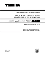
Page 4: ...ajor sections of interest All of the initial inspection storage installation and operating precautions can be found in Sections 1 and 2 while Section 3 concentrates on the theory of operation and applications Section 4 contains the equipment standard specifications and Section 5 outlines the operating modes protective features battery recharging battery low voltage tolerances alarm and panelindica...

Page 5: ...Operation 3 1 3 2 Application and Use 3 1 3 3 Power Backup 3 1 3 4 Power Conditioning 3 1 4 0 Specifications 4 1 4 1 Standard Series Specifications 4 1 4 2 Plus Series Specifications w output isolation transformer 4 3 5 0 Operating the UPS 5 1 5 1 Operation Modes 5 1 5 1 1 AC Input Mode normal operation 5 1 5 1 2 Battery Backup Mode 5 2 5 1 3 Circuit Bypass Mode 5 3 5 2 SystemProtectionFeatures 5 ...

Page 6: ... Parts Replacement 7 1 7 1 PreventiveMaintenance 7 1 7 2 PartsReplacement 7 1 7 3 Input OutputFuseRatingChart 7 1 8 0 External Dimensions Shipping Weights Panel Layout 8 1 8 1 External Dimensions for 500 through 1200 VA Model 8 1 8 2 External Dimensions for 1500 through 2000 VA Model 8 2 8 3 PanelLayout 8 3 8 4 Shipping Weights 8 3 9 0 Control Interface 9 1 9 1 Interface for 500 through 1200 VA Mo...

Page 7: ...asonic LCR12V7 2P 4 Yuasa NP7 12 4 1000 VA Panasonic LCR12V6 5BP 5 Panasonic LCR12V7 2P 5 Yuasa NP7 12 5 1200 VA Panasonic LCR12V6 5BP 6 Panasonic LCR12V7 2P 6 Yuasa NP7 12 6 1500 VA Panasonic LCR12V6 5BP 6 Panasonic LCR12V7 2P 6 Yuasa NP7 12 6 2000 VA Panasonic LCR12V6 5BP 8 Panasonic LCR12V7 2P 8 Yuasa NP7 12 8 CAUTION Do not dispose of the batteries in a fire The batteries may explode CAUTION D...

Page 8: ...perature or high humidity 2 Storage in sites subject to exposure of high levels of dust or metal particles 3 Storage on inclined floor surfaces or in sites subject to excessive vibration Beforestoring 1 Charge the units batteries 2 Place the UPS ON OFF switch in the OFF position Storing 1 Store within a temperature range of 20 to 40 deg C 4 to 104 deg F 2 For best results store the UPS in the orig...

Page 9: ...antee that the UPS will not influence some sensitive devices which are operating close by If such interference is experienced the UPS should be installed farther away from the effected equipment and or powered from a different source than that of the affected equipment 2 2 PrestartPrecautions 1 Before connecting the UPS to a power source move the ON OFF switch on the front panel See Section 8 1 to...

Page 10: ...er interruption 3 2 Application and Use Toshiba s 1400 Series of on line uninterruptible power supply UPS systems provide continuous computer grade ac power in a compact high performance and energy efficient unit The UPS unit assures safe and reliable operation of critical office equipment This can range from word processors and personal computers to mini computers and local area networks All unit...

Page 11: ...ng temperature 32 to 104 F 0 to 40 C optimal at 77 F 25 C Storage temperature 4 to 104 F 20 to 40 C Operating humidity 30 to 90 no condensation Altitude Less than 3000 ft 1000 m above sea level External dimensions 7 06W x 20 44D x 14 63H in 179W x 519D x 371H mm Weight 60 lb 27 2 kg 66 lb 29 9 kg 70 lb 31 8 kg Acoustical noise 45 dB at max output measured 3 3 ft 1 m from front panel Efficiency ac ...

Page 12: ...ting humidity 30 to 90 no condensation Altitude Less than 3000 ft 1000 m above sea level External dimensions 1 2 KVA 7 06W x 20 44D x 14 63H in 179W x 519D x 371H mm External dimensions 1 5 2 KVA 7 06W x 23 16D x 14 63H in 179W x 588D x 371H mm Weight 76 lb 34 5 kg 96 lb 43 6 kg 106 lb 48 2 kg Acoustical noise 45 dB at max output measured 3 3 ft 1 m from front panel Efficiency ac dc ac 89 89 89 Sw...

Page 13: ...Environment Operating temperature 32 to 104 F 0 to 40 C optimal at 77 F 25 C Storage temperature 4 to 104 F 20 to 40 C Operating humidity 30 to 90 no condensation Altitude Less than 3000 ft 1000 m above sea level External dimensions 7 06W x 20 44D x 14 63H in 179W x 519D x 371H mm Weight 80 lb 36 4 kg 85 lb 38 6 kg 92 lb 41 8 kg Acoustical noise 45 dB at max output measured 3 3 ft 1 m from front p...

Page 14: ...orage temperature 4 to 104 F 20 to 40 C Operating humidity 30 to 90 no condensation Altitude Less than 3000 ft 1000 m above sea level External dimensions 7 06W x 23 16D x 14 63H in 179W x 588D x 371H mm Weight 117 lb 53 2 kg Acoustical noise 45 dB at max output measured 3 3 ft 1 m from front panel Efficiency ac dc ac 89 Switches Bypass switch Automatic bypass is provided when the run switch is in ...

Page 15: ... main circuit Power flow in AC input mode for 1500 and 2000 VA Models Both of the above illustrations show circuit power flow in the ac input mode The UPS unit s rectifier included in a boost chopper circuit converts ac input power to dc power This dc power runs the unit s transistor inverter and charges the batteries The boost chopper circuit maintains a constant voltage with current limiting for...

Page 16: ...e above illustrations show power flow during the battery backup mode When commercial ac power failures occur the UPS s batteries instantly begin supplying dc voltage to the UPS s main inverter circuit This circuit changes inverts the dc power into ac power The ac power is available at the unit s output receptacles This back up process will continue until the UPS s battery voltage drops below a spe...

Page 17: ...lt the power flow is automatically switched from the unit s main circuit to the bypass circuit mode Power flow through the bypass is shown in the above illustrations This change over occurs automatically in approximately 4 milliseconds The switching period is not long enough to cause interruptions to occur in most UPS equipment loads After repairing the cause of the inverter shutdown the energy fl...

Page 18: ...t Overload Input abnormal Low battery level Input abnormal Lowbattery level Notes 1 TheUPS sRECT CHOPPERandINVERTER althoughseparateelectrical circuits are physically located on the same heat sink This is applicable to all models 2 The two UPS rear panel output receptacles are supplied from the UPS inverter section through separate 15A output fuses applies to the 1500 and 2000 VA model only Thus a...

Page 19: ...Under Overload Overheat voltage voltage OC OV UV OL OH UPS Protection Features 5 3 Front Panel Indicator LED Functions 1 AC LINE This green LED lights when normal ac input power is being supplied to the UPS unit 2 INVERTER This green LED lights when the inverter output voltage is normal 3 FAULT ThisredLEDlightswhenanovercurrent overvoltage overload or overheating problem is detected Operation of t...

Page 20: ...e voltage Fully charged Discharge shut offpoint Charging 0 4 amp A 0 0 The recharge process usually consists of three periods During the first period the current is maintained at approximately 0 4 amperes In the second period the constant voltage control starts and the current gradually decreases as the batteries continue to charge In the third period a slight current flows into the batteries to k...

Page 21: ... 750 1000 1500 in VA Nominalvoltage 36 48 60 72 72 96 36 48 60 72 in Vdc Alarmvoltage 31 7 42 3 52 8 63 4 63 4 84 5 31 7 42 3 52 8 63 4 in Vdc Shutdownvoltage 29 7 38 9 48 6 58 3 58 3 77 8 29 2 38 9 48 6 58 3 in Vdc 5 7 Audible Alarm Functions Audible alarms will sound when the UPS unit is in the battery backup mode has low battery voltage or is in an overload condition The chart shown below depic...

Page 22: ...n All UPS units contain hazardous voltages that have the potential to burn and shock These voltages exist even if main power is disconnected Only qualified personnel should perform troubleshooting or repair work on UPS units NO YES YES NO Is the input voltage Connect to input voltage aboveorbelowspecified source within correct tolerance limits NO YES Is the AC input Reset input circuit breaker cir...

Page 23: ... the fault LEDindicator lit 6 0 Troubleshooting Procedures 6 2 Inverter Indicator LED Not Lighting Is the AC line LED indicator lit 6 2 6 2 YES NO YES YES Go to 6 3 Go to 6 1 NO YES Istheinverter LEDindicator lit NO Go to 6 3 Continuenormaloperations ContactyourToshiba servicerepresentative NO ...

Page 24: ... LED lit IstheINVERTER LED lit Is AC LINE LED lit 6 1 Go to Go to 6 2 NO NO YES YES YES 1 Try the start up procedure again after connecting the equipment load 2 Reduce the load if an overload hasoccurred NO to the ON position Move the On Off switch MoveOn Offswitch to the OFF position Disconnect the equipment load from the UPS unit ...

Page 25: ... the UPS unit Replace the output fuses a 1500 or 2000 VA See note 2 page 5 4 model 6 4 6 4 Go to 6 1 NO YES Continuenormaloperations YES Go to 6 2 YES Go to 6 3 Is the fault LEDindicator lit NO Istheinverter LEDindicator lit Is AC output voltagepresent ContactyourToshiba servicerepresentative NO YES YES NO NO ...

Page 26: ...area around the unit particularly the air inlet vents clean and free of moisture and dust accumulations If the atmosphere of the installation site is very dusty use a vacuum cleaner to periodically remove dust accumulations from the system 7 2 Parts Replacement The following list shows recommended intervals for periodic replacement of certain UPS parts 1 Batteries In order to maintain system relia...

Page 27: ... Panel Layout 8 1 External Dimensions for 500 through 1200 VA Models 8 1 Front View RearView Side View connector cable power Input DB 9 receptacles Output Airvents Airvents On Off switch Fuse 20 44 7 06 14 63 Dimensions are in inches RS 232C optional ...

Page 28: ...l Layout 8 2 External Dimensions for 1500 and 2000 VA Model 8 2 Front View RearView Side View connector cable power Input DB 9 receptacles Output Airvents Airvents On Off switch 23 16 7 06 14 63 Dimensions are in inches Fuse Fuse Breaker RS 232C optional ...

Page 29: ...27 2 800 VA 66 29 9 1000 VA 70 31 8 1200 VA 76 34 5 1500 VA 96 43 6 2000 VA 106 48 2 500 VA Plus 80 36 4 750 VA Plus 85 38 6 1000 VA Plus 92 41 8 1500 VA Plus 117 53 2 8 0 External Dimensions Panel Layout Shipping Weights 8 3 Panel Layout 8 3 8 4 Shipping Weights ...

Page 30: ...erface for 1500 and 2000 VA Models 9 1 LOW BATTERY UTILITY FAILURE COMMON 1 3 5 9 8 7 6 5 UTILITY FAILURE COMMON LOW BATTERY ON UPS ON BYPASS DB9FEMALECONNECTOR NOVELLTYPEINTERFACE DB9MALECONNECTOR AS 400TYPEINTERFACE UTILITYFAIL NC Jumper Selectable to NO LOWBATTERY NO ALLSIGNALS NO ...

Page 31: ...TOSHIBA INTERNATIONAL CORPORATION INDUSTRIALDIVISION 13131 West Little York Rd Houston Texas 77041 Tel 800 231 1412 Fax 713 466 8773 Telex 762078 World Wide Web http www tic toshiba com Printed in U S A ...

Reviews: