Siemens SITRANS FEC920, User Manual
The Siemens SITRANS FEC920 is a cutting-edge device utilized in process analytics. For a smooth setup, refer to the Quick Start Manual available for free download at manualshive.com. This invaluable manual provides step-by-step instructions, ensuring a hassle-free experience with your new Siemens SITRANS FEC920.
Share
Download


Reviews:
No comments
Related manuals for SITRANS FEC920
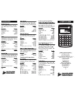
3265
Brand: Calculated Industries Pages: 2
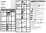
AS-1200
Brand: Canon Pages: 2
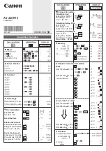
AS-220RTS
Brand: Canon Pages: 2
F-715SG
Brand: Canon Pages: 20
KS-1200TS
Brand: Canon Pages: 2
F-788dx
Brand: Canon Pages: 2
F-789SGA
Brand: Canon Pages: 35
Canola SX-300 series
Brand: Canon Pages: 60
F-719SG
Brand: Canon Pages: 2
WS-1210Hi III
Brand: Canon Pages: 2
MP25-MG
Brand: Canon Pages: 2
MP27-MG
Brand: Canon Pages: 2
LS-270H
Brand: Canon Pages: 2
P1-DTSC
Brand: Canon Pages: 2
WS-1400H
Brand: Canon Pages: 2
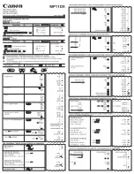
MP11DX - Printing Calculator
Brand: Canon Pages: 4
MP18DII
Brand: Canon Pages: 2
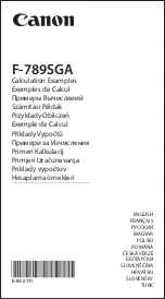
F-789SGA
Brand: Canon Pages: 40


