1.2
1.3
Einbau vorbereiten – Preparing for mounting
1.4
Gerät montieren – Mounting the device
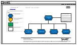
2.2
Stromversorgung anschließen – Connecting the power supply
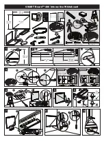
Gerät einbauen
Mounting the device
1
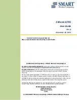
Gerät anschließen
Connecting the device
2
2.1
Potenzialausgleich – Equipotential bonding
Zulässige Einbaulagen – Valid Mounting positions
Vor Einbau und Inbetriebnahme – Before mounting and commissioning
1.1
WICHTIG: Beachten Sie alle dem Gerät beiliegenden
Dokumente und die Betriebsanleitung, bevor Sie das
Gerät einbauen und anschließen. Die vollständige
Dokumentation des Geräts finden Sie auf der beiliegen-
den DVD "Documentation and Drivers" und im Internet
https://www.siemens.de/simatic-ipc-doku-portal
).
IMPORTANT: observe all documents enclosed with the
device and the operating instructions manual before
mounting and connecting the device. You find the
complete documentation of the device on the enclosed
"Documentation and Drivers" DVD and on the internet
Das Handbuchsymbol weist auf detaillierte Informationen in der Betriebsanleitung hin.
The manual symbol refers to detailed information in the operating instructions.
Sichern Sie die angeschlossenen
Leitungen zur Zugentlastung mit
Kabelbindern an den markierten
Befestigungselementen.
Achten Sie darauf, dass die
Leitungen durch die Kabelbinder
nicht gequetscht werden.
Use cable ties to secure the
connected cables to the selected
fixing elements for strain relief.
Make sure that the cables are not
crushed by the cable tie.
2.3
Leitungen sichern – Securing the cables
For use in Canada:
Arrêtez les câbles raccordés
pour une décharge de traction
avec les attache-câbles sur les
éléments de fixation marqués.
Veillez à ce que les câbles ne
soient pas écrasés par les
serre-câbles.
https://www.siemens.com/simatic-ipc-doku-portal
50 °C
0 °C
mm
M4
11
16 mm
²
6 mm
2
3
Montage an der Rückseite
Mounting at the rear side
Montage an einer Seite
Mounting at one side
PZ2
0,8 Nm
14
80
1
2
Hutschienenmontage
Mounting on a standard rail
Wandmontage / Wall mounting
Montageschiene befestigen
Fixing the mounting rail
Erforderlicher Frairäume
Required clearances
2
3
1
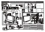
Material
Bohrungsdurchmesser Befestigungselement
Beton
Gipskarton, mind. 13 mm dick
Metall, mind. 2 mm dick
Dübel, ∅ 6 mm, 40 mm lang
Schraube, ∅ 4 mm, 40 mm lang
Kippdübel, ∅ 12 mm, 50 mm lang
Schraube M4 x 15
Mutter M4
Entsprechend der
Vorgabe des verwendeten
Befestigungselements
wählen
Material
Bore diameter
Fixing element
Concrete
Plasterboard, min. 13 mm thick
Metal, min. 2 mm thick
Anchor, ∅ 6 mm, 40 mm long
Screw, ∅ 4 mm, 40 mm long
Toggle plug, ∅ 12 mm, 50 mm long
Screw M4 x 15
M4 nut
Select according to the
specification of the
mounting elements used
Befestigen Sie die Transceiver Unit mit zwei Schrauben M4 über die beiden Langlöcher der
Montageschiene.
Fix the Transceiver Unit with two screws M4 via the two oblong holes of the mounting rail.
IFP1500 V2
1
6 mm
2
3
M
L+
4
8
7
0/OFF
Den
mitgelieferten
Ferrit wie
abgebildet
montieren.
Mount enclosed
ferrite as shown.
max. 200 mm
6
4
TX 20
4 mm
²
5
Informationen zu weiteren Montagevarianten / Information on additional mounting variants
IFP1
500
500
0
0
V2
V
V
V
5
Verwenden Sie für die DC 24 V-Versorgung nur Netzgeräte mit sicherer elektrischer Trennung nach
IEC 61010-2-201 oder IEC 60950-1 gemäß dem Standard SELV/PELV.
Die Versorgungsspannung darf nur innerhalb des angegebenen Spannungsbereichs liegen.
Use only power supply units with safety isolation complying with IEC 61010-2-201 or IEC 60950-1
according to the SELV/PELV standard, for the 24 V DC supply.
The supply voltage must be within the specified voltage range.
1
2
3
C
M
Y
CM
MY
CY
CMY
K
ifp_v2_transceiver_quick_install_guide_page_1.eps 1 09.08.2019 10:30:54
ifp_v2_transceiver_quick_install_guide_page_1.eps 1 09.08.2019 10:30:54