background image


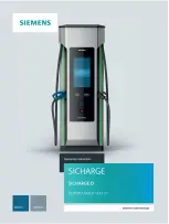
Summary of Contents for SICHARGE D 8EM5907-0AA00-1AA7.01

Page 1: ......

Page 2: ... 2 Description 3 Transport and storage 4 Installation and mounting 5 Commissioning 6 Operation 7 Behavior in the event of errors and error messages 8 Maintenance and service 9 Disposal 10 Technical specifications 11 Declaration of Conformity 12 List of abbreviations and explanation of terms A Checklist for commissioning B ...

Page 3: ...d only by personnel qualified for the specific task in accordance with the relevant documentation in particular its warning notices and safety instructions Qualified personnel are those who based on their training and experience are capable of identifying risks and avoiding potential hazards when working with these products systems Proper use of Siemens products Note the following WARNING Siemens ...

Page 4: ...sign 16 2 5 Industrial Security 17 2 6 Identification of the device 18 3 Description 20 3 1 Product overview 20 3 2 Configuration options 22 3 3 Display elements and operator controls 23 3 4 Charging ports 29 3 5 Design of the charging station 32 3 6 Dispenser 35 3 7 Electrical protection devices 36 3 8 Routers 37 3 9 Siemens Configuration Backend 38 3 10 OCPP backend 39 4 Transport and storage 40...

Page 5: ...Install the cable gland plate 62 5 5 6 Installing baseboards 64 5 6 Connecting the charging station 65 5 6 1 Safety instructions 65 5 6 2 Mains connection 66 5 6 3 Dispenser 70 5 6 4 Mounting the roof and filter cover 73 6 Commissioning 74 6 1 Safety precautions before initial commissioning 74 6 2 Switch on charging station 74 6 3 Switching off the charging station 76 7 Operation 77 7 1 Safety ins...

Page 6: ...intenance plan 91 9 3 Servicing the charging station 94 9 3 1 Cleaning the touch screen 94 9 3 2 Cleaning the cabinet 95 9 3 3 Replacing an air filter 96 9 4 Spare parts 97 10 Disposal 98 11 Technical specifications 99 12 Declaration of Conformity 100 A List of abbreviations and explanation of terms 101 B Checklist for commissioning 102 Index 104 ...

Page 7: ...instructions Keep the operating instructions for the entire service life of the charging station Make the operating instructions easily accessible at all times for all persons involved If you transfer the charging station to third parties also pass along the operating instructions Using the operating instructions How to use the operating instructions correctly Make the operating instructions avail...

Page 8: ...contained in it pursuant to the conditions applicable to the product Siemens accepts no liability for the use of the open source software over and above the intended program sequence or for any faults caused by modifications to the software For legal reasons we are obliged to publish the original text of the license conditions and copyright notices Read the information on this provided for downloa...

Page 9: ...he following basic safety instructions Guidelines and regulations In order to ensure comprehensive safety adhere to the following guidelines and regulations Guidelines for occupational safety Regulations for prevention of accidents Trade regulations Technical connection conditions of the power supply unit Building regulations Generally accepted rules of technology Target group These operating inst...

Page 10: ...HARGE D charging station is intended for charging electric vehicles according to EN 61851 1 EN 61851 23 and must not be used for other vehicles or purposes Any other use or use that goes beyond the use described here is not intended and represents a misuse of the device The charging station must be set up in accordance with the statements in these operating instructions Transport installation main...

Page 11: ... zone Do not use the charging station in the event of fire Protection against electromagnetic fields The charging station meets the requirements of IEC 61851 21 2 2018 Noise immunity Class A Emission radiated Class A Emission conducted AC input Class A Emission conducted DC port Limits according to IEC 61851 21 2 2018 Note The device is intended for industrial applications The charging station als...

Page 12: ...t off at the electrical distributor Qualified personnel must dry the charging station and check it for damage Protection against unauthorized opening A lock system protects the charging station from unauthorized opening of the device doors at the front and back Keep the key for the door locks safe against access by unauthorized persons Only make the key available to authorized persons for work in ...

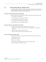
Page 13: ...etected dangers can result in accidents with serious physical injury or death Check the presence of all safety signs and warnings using the operating instructions Replace missing safety signs and warnings Do not remove safety signs and warnings Replace unrecognizable safety signs and warnings Only use undamaged equipment or parts WARNING Electric shock in case of damaged equipment Improper handlin...

Page 14: ...nection at electric distributor 3 Ensure that electric distributor is de energized 4 Ground and short circuit at the electric distributor 5 Erect barriers around or cover adjacent live parts Prepare to switch on again after work is finished After finishing and checking the work prepare the restart as follows Inform persons no longer required that the work is completed and no further work is permit...

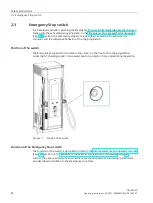
Page 15: ...ehavior of the charging station Position of the switch The Emergency Stop switch is located in the center on the front of the charging station under the AC charging socket Its recessed position protects it from unintentional operation Figure 2 1 Position of the switch Function of the Emergency Stop switch The function of the switch is described in detail in the Display elements and operator contro...

Page 16: ...ch in the direction of the arrow until it is released The charging station will automatically start to return to readiness for charging This may take a few minutes The LED strips signal this process and light up in white After a successful self check the LEDs light up green The start menu is shown on the display The charging station is back in normal operating mode Misuse of the switch To prevent ...

Page 17: ...on and on the packaging for safe handling of the charging station Safety signs on the packaging The following safety sign is attached to the packaging of the charging station Safety sign Meaning Warning of general danger Safety sign in the charging station The following safety sign is attached to the charging station Safety sign Meaning Warning of dangerous voltage ...

Page 18: ...nnected to the enterprise network or the Internet if and to the extent that it is necessary and with appropriate security measures in place e g using firewalls and network segmentation Through suitable configuration of the charging station and OCPP backend the operator must ensure that only secure RFID cards can be used for authorization For example Mifare Classic cards are not classified as secur...

Page 19: ...7 01 2 6 Identification of the device The nameplate clearly identifies the charging station and is located in the bottom right corner on the left hand cabinet wall see Figure 2 2 The nameplate also contains the identification data of the device the manufacturer and the CE marking Figure 2 2 Position of the nameplate ...

Page 20: ...ification of the device SICHARGE D Operating Instructions 02 2021 8EM5907 0AA00 1AA7 01 19 Information on the nameplate You can find the following information on the nameplate of the charging station Figure 2 3 SICHARGE D nameplate ...

Page 21: ...d optimum use of installed power Can be expanded by up to two additional distributed DC charging points dispensers 22 kW AC charging socket with shutter Simultaneous charging of up to five vehicles Autonomous health monitoring for maximum availability Operation and environment Attractive design with status LEDs on cabinet Accessible 24 touch screen Noise optimized operation High level of protectio...

Page 22: ...c and semi public commercial and industrial areas e g Terminals Vehicle depots Company parking lots Compatibility Only vehicles that meet the following standards can be charged at the charging station Table 3 1 Standards AC charging Type 2 IEC 61851 1 IEC 62196 Mode 3 CCS 2 IEC 61851 23 IEC 62196 Mode 4 CHAdeMO CHAdeMO 1 2 JEVS G105 Communication DIN SPEC 70121 IEC 61851 24 ISO 15118 ...

Page 23: ... uncooled CHAdeMO 200 A uncooled DC charging cable 2 right CCS 250 A uncooled CCS 500 A cooled Charging cable length 3 10 m prepared DC outlet for dispenser 1x CCS up to 500 A 2x CCS 500 A each AC charging socket 22 kW Included by default Touch screen 24 for barrier free access LED status display Per DC charging cable by default RFID reader Included by default Emergency stop Included by default Li...

Page 24: ...The charging station is equipped with a central touch screen Using two buttons on the top and bottom edge of the screen the display on the 24 touch screen can be set to three different heights according to the desired viewing height This allows barrier free and convenient operation The charging station therefore complies with DIN 18040 The large viewing angle of the display makes it easier to reco...

Page 25: ...tion powered up not ready to charge without critical error Green Ready to charge Red Critical error or emergency stop activated Blue DC charging cable connected to vehicle Pulsating blue Active charging RFID reader The RFID reader is located below the touch screen The symbol lights up continuously as soon as user is to be authenticated via this interface Charging plug and holder The DC charging ca...

Page 26: ... again when the charging process is complete The charging cable with Type 2 plug must be provided by the user and it must support Mode 3 The following table illustrates the pin assignment of the socket Table 3 4 Pin assignment of the AC charging socket No Contact Use Proximity Pilot PP Detects presence of the plug Control Pilot CP Communication signal between vehicle and charging station L1 Line c...

Page 27: ...e of the circuit breaker also ends charging via the AC charging socket and dispenser remote and non autonomous charging points Existing interlocks of the charging plug are released by the charging station The LED strips of the charging station light up red Charging is not possible in the emergency stop state The Out of service message remains on the display of the charging station The auxiliary po...

Page 28: ...placing the lock cylinders The door locks and the door opener secure access to the inside of the charging station At the front the lock cylinder is in the cover at the top left next to the device door Remove the cover by pressing upwards There is a pushbutton under the cover which can be used to open the door Figure 3 3 Lock cylinder front ...

Page 29: ...nder rear Position switches detect whether the doors are closed If the doors are opened without authorization during operation despite the lock system a hazard shutdown is initiated The circuit breaker is triggered and interrupts the power supply to the power branches Power supply to the control system is maintained If the doors are to be opened the charging station must first be shut down This is...

Page 30: ...imarily with respect to their connectors and the number and usage of the individual pins CCS plug Combo 2 Figure 3 5 CCS plug Combo 2 Table 3 5 Pin assignment of the CCS plug Combo 2 No Contact Use Control Pilot CP Communication signal between vehicle and charging station Proximity Pilot PP Protective Earth PE Protective conductor DC positive pole DC Positive pole for DC charging DC negative pole ...

Page 31: ...n the interlock between plug and vehicle is active A special feature of the CHAdeMO plug is an interlock button above the handle After the charging process ends the button has to be pressed to remove the plug from the vehicle inlet An LED 11 on the handle lights up when the interlock between plug and vehicle is active AC charging socket The AC charging socket provides a third charging port on the ...

Page 32: ...Standard IEC 62196 3 Rated current 250 A uncooled 500 A cooled Rated voltage 1000 V DC Cable outer diameter 32 0 0 4 mm 35 7 0 4 mm Power contacts DC DC Operating cycles 10 000 Insertion and withdrawal force 100 N Max current usually not possible continuously because there may be derating based on the cooling capacity of the pump ambient temperature cable length vehicle inlet temperature CHAdeMO T...

Page 33: ... result for example from fewer features due to the configuration The charging station is subdivided into five different areas Four areas are arranged above one another while the molded door represents the fifth area The following figure shows the charging station with open door from the front Protective cover in front of the copper bars and circuit breaker connection of the power supply cables Pro...

Page 34: ... dispensers are also located here The AC DC converters are in the center area of the charging station behind a cover Among other things they guarantee galvanic isolation between the mains and the vehicle The automation devices are located above the converter cover On the back of the door the AC power line is at the bottom the devices for consumption measurement at the side and the routers for wire...

Page 35: ...ht next to the coolant pump Above them are the AC busbars to which the AC DC converters are connected The DC distribution system including switching matrix DC filter output fuses and electronic components for monitoring the charging outputs is located above the AC DC converter The outlets for the charging cables and the radial fans are located under the roof Cooling unit Shielded AC line filter AC...

Page 36: ...d for the CCS charging standard With parallel operation of the two busbar systems a charging current of up to 1000 A is possible This charging current requires the use of all DC AC converters of the charging station As a result simultaneous charging via the DC charging cable is not possible at this time Laying cables between the charging station and the dispenser To connect dispensers to the charg...

Page 37: ...W 32 A When the user uses an AC charging cable for lower charging powers this is automatically adapted to the rated values of the cable If the current is more than 1 3 times greater than this value the charging station aborts the charging process The control system monitors the DC output current per charging outlet When a measured current value exceeds the preset limits the charging process is abo...

Page 38: ...ssioning of the charging station by the operator With the door open the router is located on the right A second router can be installed for wireless connection to the OCPP backend With the door open it is located on the left The SIM card required for this must be provided by the operator Use of an M2M SIM card is recommended The SIM card slots on the devices are in the center between the connectio...

Page 39: ... of a charging station location customer can be displayed and edited Configuration display change per charging station OCPP configuration General timeout and screen configuration e g logout screen after 30 s or wait time after repeated pressing of the emergency stop Configuration of the permissible noise generation depending on day of the week time Router configuration WAN type Ethernet LTE Wi Fi ...

Page 40: ...backend The following messages with corresponding functions from the two profiles Core and Local Auth List Management are supported by the charging station Table 3 9 Message with corresponding functions Message Function Authorize Organize authorizations for starting or ending a charging process BootNotification Query information on the configuration of the device ChangeConfiguration Make change to...

Page 41: ...duct The packaging materials for export by air or sea correspond to the IPCC standard ISPM no 15 Make sure that the hoisting gear and machines used are suitable for the weight of the charging station Also pay attention to the dimensions of the charging station For specific information refer to the document with the order number 8EM5907 0AA00 2AA7 Safety instructions WARNING Danger to life when sta...

Page 42: ...on to the center of gravity of the charging station The center of gravity is marked on the device and on the packaging Note the weight of the charging station Only transport the charging station in a vertical position The forks of the forklift must protrude at the rear of the transport pallet Note Transporting charging stations on load carriers The charging station is always delivered fastened to ...

Page 43: ...livery state To transport the charging station to the installation site with a forklift proceed as follows 1 Drive into the load carrier with the forks on the longitudinal side 2 Drive in until the forks protrude on the other side 3 Lift the charging station vertically paying attention to the center of gravity of the device Avoid uneven ground 4 Transport the charging station standing upright to t...

Page 44: ...e with a crane proceed as follows 1 Mount the orderable crane lugs at the four corners of the enclosure frame on the roof When using your own crane lugs ensure that they have an M12 thread that is 25 to 30 mm long and are suitable for the weight of the charging station 2 Hook the hoisting gear into the crane lugs 3 Lift the charging station vertically 4 Transport the charging station hanging uprig...

Page 45: ...kage must be arranged on the truck in a form fitting manner For additional load securing anti slip mats must be placed under the entire contact area between the transport pallet and the loading area of the truck The cargo must be secured in combination with an anti slip mat lashing material and a lashing force of 400 daN A securing strap is placed around the package The attachment frame in the roo...

Page 46: ...sulated wood pallet In addition foil protects the charging station from dirt particles and moisture The packaging consists of the following elements Export packaging according to IPPC standard ISPM15 Solid wooden crate Base plate Pallet base PE cover Attachment frame Straps for securing load The box of accessories is attached to the side of the packaged charging station Note Air packaging cannot b...

Page 47: ...he wooden box from moisture and salt air The packaging consists of the following elements Export packaging according to IPPC standard ISPM15 Plywood box suitable for container stowing Pallet base PE cover Attachment frame Straps for securing load The box of accessories is attached to the side of the packaged charging station Use of desiccant method with aluminum compound foil for preservation Clim...

Page 48: ...internal area The storage location must meet the following conditions Horizontal surface Protection against mechanical stress e g from shock vibration Dust free Low pollutant atmosphere Room temperature as constant as possible Permissible relative humidity 5 to 70 non condensing Long term storage NOTICE Material damage due to excessive storage time If the electronic components of the charging stat...

Page 49: ...tion WARNING Danger to life when standing under lifted loads If hoisting gear or load handling equipment fail a lifted load can drop If you are in the hazardous area under or next to the lifted load at this time death serious injury and material damage may result Always use hoisting gear and load handling equipment properly Do not stay in the hazardous area under or next to a lifted load WARNING F...

Page 50: ... for example Warning signs Safe location of the SICHARGE D dispenser Barriers Training of drivers and operators Sufficient lighting CAUTION Safety area for mounting Create a safety area around the mounting surface with warning signs and barriers CAUTION Use personal protective equipment PPE Use the required personal protective equipment for the work such as Protective shoes Helmet Safety vest Glov...

Page 51: ...of drivers and operators Sufficient lighting Selection criteria for a safe location Select the location of the charging station in such a way that all operations are safe The charging station itself must not pose a risk to persons or vehicles Note Do not install the charging station in an open area Do not install the charging station in an open area without an interception rod or external lightnin...

Page 52: ...ure proper ventilation of the charging station you need to maintain the following minimum clearances Figure 5 1 Minimum clearances of SICHARGE D top view However we recommend installing the charging station free standing as far as possible If two charging stations are installed next to one another double minimum clearances apply between the two devices In addition a minimum clearance of 20 cm betw...

Page 53: ... of 55 C the available charging power is restricted Direction of air flow The supply air enters the two sides and the back of the charging station from below The air flow within the charging station goes from the bottom to the top The warm exhaust air escapes on both sides and the back This means that it does not hit the operator at the front of the charging station Therefore the operator must ens...

Page 54: ...ng Instructions 02 2021 8EM5907 0AA00 1AA7 01 53 Bumper To protect the charging station against contact by vehicles impact protection is recommended e g in the form of a bollard Bumper Charging station Figure 5 2 Example Correct position of the bumper and charging station ...

Page 55: ...ing to the ground conditions on site Note Illustrations of example The illustrations below serve as examples Plan and adjust the base area together with the foundation planner in accordance with your circumstances Securing points In order to be able to mount the station the following drill holes must be available for the securing points Cable bushing for dispenser cable Cable bushing for power sup...

Page 56: ...e the maximum permissible bending radii of the connecting cables you are using Lay communication control and auxiliary cables separately and protected from the power cables To avoid electromagnetic interfaces a minimum clearance of 25 cm is recommended Also avoid routing the cables parallel to the power cables and if possible route the cables orthogonally to the power cables Observe the country sp...

Page 57: ...ces has been exceeded by red coloring Indicator tube Figure 5 5 Schematic example Shock indicator The shock indicator monitors any G forces acting during the entire transport If the charging station is subjected to unacceptably high G forces during transport the shock indicator is triggered The indicator tube shows that the tolerance limit for G forces has been exceeded by red coloring Perform a v...

Page 58: ...the delivery is incomplete or that there is transport damage document the damage first Then submit a damage report Documenting damage Take immediate action to determine the exact extent cause and origin of the damage Take immediate and appropriate measures to limit the damage In particular document the damage as follows Photograph the damage Record all known information on the damaging event e g l...

Page 59: ...al conductors properly from environmental influences such as dirt and moisture Preparing the network cable The charging station offers the possibility of connection to the network via an Ethernet cable Ensure proper protection of the cable from environmental impacts such as dirt and moisture Read the information on laying in section 5 3 Page 54 Preparing dispenser cables If dispensers are to be co...

Page 60: ...en the device door remove the cable gland plate below the connection bars on the circuit breaker and close the door 2 Repeat this step on the back of the device if you want to connect dispensers to the charging station 3 Procedure with crane or forklift Using a crane recommended Mount the orderable crane lugs at the four corners of the enclosure frame on the roof When using your own crane lugs ens...

Page 61: ...2021 8EM5907 0AA00 1AA7 01 Positioning the charging station 1 Release the charging station carefully above the base area Position the four feet with their slots using the concrete anchors 2 Do not damage the concrete anchors when placing them on the base area Figure 5 6 Positioning the charging station ...

Page 62: ...er lifting If you lift the charging station improperly the device may tip over Tipping of the charging station can cause death serious injury and material damage Only qualified personnel should lift the charging station Only use approved hoisting gear Pay attention to the center of gravity of the charging station Note the weight of the charging station Only lift the charging station in a vertical ...

Page 63: ...n and the power drawn Adapt the cable gland plate according to your connection To do this proceed as follows 1 Open the device door 2 For each conductor of the mains connection drill a hole at the relevant position in the cable gland plate so that you can optimally pass the conductors through and connect them 3 If you wish to connect to your charging station via Ethernet also drill a hole for the ...

Page 64: ... connect dispensers to the charging station you must also prepare the second cable entry plate on the back below the busbar taps In the work steps proceed in a similar way as with the mains connection Take into consideration all required cables such as power cables communication cables any auxiliary supply cables etc Figure 5 8 Cable gland plate ...

Page 65: ...ollows 1 Start with the rear baseboard Use two M6 Allen screws 5 mm Allen wrench to screw the rail to the rear device support feet 2 The two lateral baseboards are inserted into the rear baseboard and then fixed to the two front device support feet with M6 Allen screws 3 The front baseboard is also inserted Disassembly is only possible in reverse order Figure 5 9 Baseboard assembly ...

Page 66: ...the parts can lead to serious injury or death To ground the charging station connect the protective conductor properly WARNING Qualified personnel Only qualified and trained persons may work on SICHARGE D Only qualified and instructed electricians may work on the SICHARGE D WARNING Fall arrester Use approved protective equipment to protect persons components and tools against falling from a workin...

Page 67: ...e measures such as Warning signs Safe location of SICHARGE D Barriers Training of drivers and operators Sufficient lighting Keep the installation site tidy CAUTION Safety area for mounting Create a safety area around the mounting surface with warning signs and barriers CAUTION Risk of crushing or cuts When mounting look out for moving parts and protruding cables and bolts CAUTION Risk of tripping ...

Page 68: ...oved the protective cover in front of the connections of N L1 L2 and L3 You have inserted all cables on the supply side into the cabinet and installed the cable gland plate again Connections for the power supply cable Connection for N Connection for L1 Connection for L2 Connection for L3 Connection for PE Figure 5 10 Connections of the power supply cable ...

Page 69: ...ctor First connect the protective conductor of the power cable before proceeding with the installation of the remaining conductors To do this proceed as follows 1 Insert the M10 screws from behind through the square cutouts of the connection rails 2 Contact a connection bar with two conductors Ensure that there is one cable lug on each side of the copper busbar 3 Tighten the fastening nut with the...

Page 70: ...ernet cable If you want to establish a connection between the OCPP backend and the charging station via Ethernet you need to connect the Ethernet cable to the right hand port see following figure Secure the cable with a strain relief The connection point also takes on the function of overvoltage protection Figure 5 12 Connecting the Ethernet cable ...

Page 71: ...sbars on the back of the device Use the fastening material pre mounted on the connection bars of the charging station Also connect the required conductors for auxiliary power supply 230 V AC communication and integration into the control system of the charging station The connections for these cables are located on the device panel on the front Connections for the DC cable Connection terminal DC C...

Page 72: ...tightening torque of 40 Nm 5 Mark the drawn connections for example with a red paint stick Connecting DC and DC conductors Connect the DC DC conductors of the dispenser cable To connect a DC conductor follow these steps 1 If necessary insulate the cable lug sleeve to maintain the minimum clearances and creepage distance 2 Insert the connection bolt through the screw holes of the cable lug and copp...

Page 73: ... The connections are intended exclusively for supplying dispensers These circuits are not protected against residual currents e g by a residual current circuit breaker Integration into the control system of the charging station The dispensers are not autonomous charging points Many components are only present in the central charging station including the control system for example Consequently the...

Page 74: ...vided towards the front of the charging station 3 Screw the roof onto the left and right side from the bottom with two M6 combi screws from the box of accessories 4 Reinstall the filter box and secure it again with the four quarter turn fasteners 5 Place the filter cover from the box of accessories onto the roof and mount the grounding cable on the threaded bolt in the filter cover 6 Remove the re...

Page 75: ...gged into the plug holder before commissioning the charging plug can be damaged This can cause injury or damage to property when the charging station is switched on Before switching on the charging station make sure that the charging plug is in the plug holder Leave the charging plug in the plug holder during the entire switch on process DANGER Risk of electric shock when moist due to condensed wa...

Page 76: ...ces are in the AC input area the automation area and in the door 3 Close the cabinet doors 4 Make sure that the cabinet door is locked 5 Switch on via the upstream switching device Automatic starting of the charging station The charging station starts automatically Wait until the charging station is fully started The LED strips light up white initially during startup In ready to operate state the ...

Page 77: ... service personnel on location can open the door of the charging station Supply to the control system and the display is maintained If the charging station must be disconnected from the power supply for further work e g to replace components this is done with the reboot command via the Configuration Backend When the boot screen appears on the display the FC12 fuse in the upper area must be actuate...

Page 78: ...n The touch screen is the central display and operator control of the charging station Only use your fingers or a touch pen to operate the touch screen Follow the instructions for cleaning and care NOTICE Damage due to unsuitable objects If you touch the touch screen with unsuitable objects you will greatly reduce the service life of the display In severe damage occurs the touch screen may even fa...

Page 79: ...arting the charging process Getting started The language is selected by tapping on the respective greeting in the desired language If you tap at any other point instead the default language or the last selected language is automatically selected highlighted left and white in this case English Figure 7 1 Start charging ...

Page 80: ...cess by connecting your vehicle directly to the charging cable or the AC charging socket Authentication The configuration in the backend determines whether authentication is required or not If no authentication is requested the charging process is free for the customer If authentication is required up to three options are available These are login via RFID standard PIN or QR code Follow the instru...

Page 81: ...is locked and the charging process begins after a brief preparation period The display switches again and various information on your charging process is displayed A customer charging cable is required for charging at the AC charging socket In addition to the protective cover the socket has an integrated shutter Lift the protective cover to connect the charging cable plug to the charging station I...

Page 82: ...e is currently displayed Figure 7 3 Charging Timeout A countdown begins after a long period of inactivity timeout Without interaction you are automatically logged off after this period and the display switches to the main menu Alternatively you can also return directly to the main screen via the display and log off After log off you can view the details of your charging process again at any time D...

Page 83: ...ng process manually you must be logged in Switch to the detail view of your charging process You can end the charging process by pressing the Stop charging button on the bottom right You will be asked if you want to end the charging process Confirm by tapping the button on the bottom right again Figure 7 4 Stopping the charging process Depending on the configuration of the backend users may need t...

Page 84: ...ructions 02 2021 8EM5907 0AA00 1AA7 01 83 7 5 Calling the help function Help can be shown in the upper right hand corner in almost every view The operator can import the telephone number of the service hotline via the Configuration Backend Figure 7 5 Service hotline ...

Page 85: ... error messages to the OCPP backend see section 3 10 Page 39 and the Configuration Backend see section 3 9 Page 38 On the central touch screen the charging station provides information through the following messages Error messages in full screen mode Emergency Stop pressed error message Page 85 Out of service error message Page 86 Error messages in the menu Outlet not available error message Page ...

Page 86: ... following error message Figure 8 1 Emergency Stop pressed error message EMERGENCY STOP state The emergency stop function switches off the power supply of all charging outlets Any charging in progress is aborted immediately The charging station switches to the safe emergency stop state The control system communication with the operator and the display remain active The LEDs light up red In the eme...

Page 87: ...informed that intervention on site is required This message contains additional information about the exact cause of the error The touch screen shows the following error message Out of service error message The display shows the Out of service error message in full screen mode The charging station cannot be operated in this state Figure 8 2 Out of service error message End error state The service ...

Page 88: ... is affected by an error case only this charging outlet is locked selectively A complete failure of the charging station does not occur This means that the availability of the charging station remains high The remaining charging outlets remain available for charging Outlet not available error message The affected outlet is highlighted in red in the outlet selection menu item Error is displayed as ...

Page 89: ...00 1AA7 01 8 4 Reinsertion of charging cable error message It may happen that the customer s own AC charging cable is not locked correctly the first time it is plugged in No charging process can be started in this case The user is then asked to plug in the charging cable again The following error message appears on the display Figure 8 4 Connection failed ...

Page 90: ... inside the station when the charging station is disconnected from the power supply Observe the five safety rules for electrical work Page 13 WARNING Electrical shock due to residual charges in capacitors After switching off the power supply to the charging station the capacitors begin to discharge Live parts remain under dangerous electrical voltage for up to 10 minutes during discharging Touchin...

Page 91: ...rriers CAUTION Use personal protective equipment PPE Use the required personal protective equipment for the work such as Protective shoes Helmet Safety vest Gloves Protective goggles CAUTION Risk of crushing or cuts During maintenance and service pay attention to moving parts and protruding cables and bolts NOTICE Damage to property due to foreign objects inside the station During maintenance work...

Page 92: ...o maintain the functionality and operational safety of the charging station Times of testing After commissioning carry out the tests at the following intervals 6 months after commissioning 12 months after commissioning After the first year carry out the tests every 12 months Run the tests at shorter intervals if required by the ambient conditions of the SICHARGE D charging station ...

Page 93: ...tics test Check fan for unusual running noises Check power supply unit for unusual operat ing noises Testing for proper function Check cabinet door for smooth opening Check function of the Emergency Stop switch Check whether an error message appears on the touch screen display after the switch is pressed Check automatic setting of readiness to oper ate after unlocking the pressed Emergency Stop sw...

Page 94: ...stening of the connection cables Check the fastening of the protective conduc tor connection Check the insulation of the cables for visible damage Check impeller for damage Check impeller for signs of wear deposits or corrosion Check mains connections of the charging station Check the following Type of test Checks Check to ensure proper condition Check tightening torques 40 Nm of the L1 L2 L3 N co...

Page 95: ...ng station WARNING Damage to property due to improper cleaning agents Improper cleaning agents can damage the touch screen of the charging station Therefore do not use solvents Also never use aggressive or abrasive cleaning agents Note Only clean the touch screen when it is switched off If you clean the touch screen when it is switched on you can trigger operator errors This can unintentionally pu...

Page 96: ...the exterior surfaces of the charging station Therefore do not use solvents Also never use aggressive or abrasive cleaning agents Permitted cleaning agents Use a mild non corrosive cleaning agent even in the case of heavy soiling Mild detergents are for example dishwashing liquids Deionized water is particularly suitable for cleaning the unit Cleaning the exterior surfaces of the cabinet Wipe the ...

Page 97: ...tion is within the permissible temperature range Only replace the filter mats when the device is de energized For the correct order number of the spare parts refer to the document 8EM5907 0AA00 2AA6 Replace filter mats below You need to open both device doors to access the three filter mats 1 Open the front device door 2 Loosen the two quarter turn fasteners on the filter grilles on the left and r...

Page 98: ... pull the bottom edge of the cover backwards and then downwards Place the filter cover on the roof 4 Loosen the four quarter turn fasteners of the filter box and remove it Replace the filter mat 5 Also loosen the two quarter turn fasteners on the filter grilles on the left and right Then swing the grille inwards and replace the filter mats 6 Secure the filter grille and the filter box Close the ch...

Page 99: ... of packaging material in an environmentally friendly manner or recycle the material Observe the disposal regulations and environmental protection regulations If needed contact a specialist disposal company Wooden packaging for sea and air transport consists of impregnated wood Observe the local regulations The foil of the sealed packaging is an aluminum compound foil The foil can be thermally rec...

Page 100: ...A00 1AA7 01 98 Technical specifications 11 For technical specifications refer to the document with the order number 8EM5907 0AA00 2AA7 These can be found here https new siemens com global en products energy medium voltage solutions emobility manuals html ...

Page 101: ... charging stations published in the official gazettes of the European Union Safekeeping location of the declaration of conformity SIEMENS AG keeps the EU Declaration of Conformity of the charging station available for the responsible authorities at the following location SIEMENS AG Smart Infrastructure Distribution Systems Research Development Mozartstraße 31C 91052 Erlangen Germany ...

Page 102: ...nt OCPP Open Charge Point Protocol PE Polyethylene PE Protective Earth HMI Human Machine Interface SoC State of Charge SW Width across flats RFID Radio Frequency Identification Device Terms The following terms are used in these instructions Term Meaning Backend Charging station management system Switching matrix DC distribution system for dynamic power distri bution to the individual power outlets...

Page 103: ... 5 mm Distances front and rear 654 mm height bolt anchor 50 mm 2 7 Check sufficient recesses for power cable entry 2 8 Minimum clearance 0 25 m for laying communication control and auxiliary cables to power cables possible 2 9 For TT system only Install deep grounding 3 Prepare cables Check that cables are disconnected from the power 3 1 Lay the power cable 3 2 If present Lay the Ethernet cable 3 ...

Page 104: ...late if applica ble 6 8 If dispenser Repeat work steps on the back of the charging station take comm control and auxiliary cables into consideration 6 9 Install baseboards 6 10 Install roof 7 Connect the charging station 7 1 Finally cut conductor of the power supply cable to length and apply M10 cable lug 7 2 Connect conductor to copper bars tightening torque 40 Nm mark with pen 7 3 Protective cov...

Page 105: ...necting Auxiliary power supply 71 DC cable 70 Power supply cable 66 Connecting the power supply cable 66 D DC cable Connecting 70 Decentralized charging points 35 Declaration of Conformity 100 Disposal Charging station 98 Packaging material 98 E Emergency stop Error message 85 Emergency Stop button 14 Error message Emergency stop 85 I Industrial Security 17 Installation Safety instructions 48 Inte...

Page 106: ...2 2021 8EM5907 0AA00 1AA7 01 105 R Replacing an air filter 96 S Safety instructions 8 Connecting 65 Installation 48 Maintenance and service 89 Operation 77 Safety rules for electrical work 13 Safety sign 16 T Terms 101 Touch screen Cleaning 94 ...

Page 107: ......

Reviews: