background image

CC1A7865.1en
31.10.2002

Siemens Building Technologies

HVAC Products

7

865.1

Interface RS-485

RWF40...

The RS-485 interface is used for integrating RWF40… controllers into data networks
via MOD bus protocol.

Application examples:

Process visualization

Plant control

Reporting

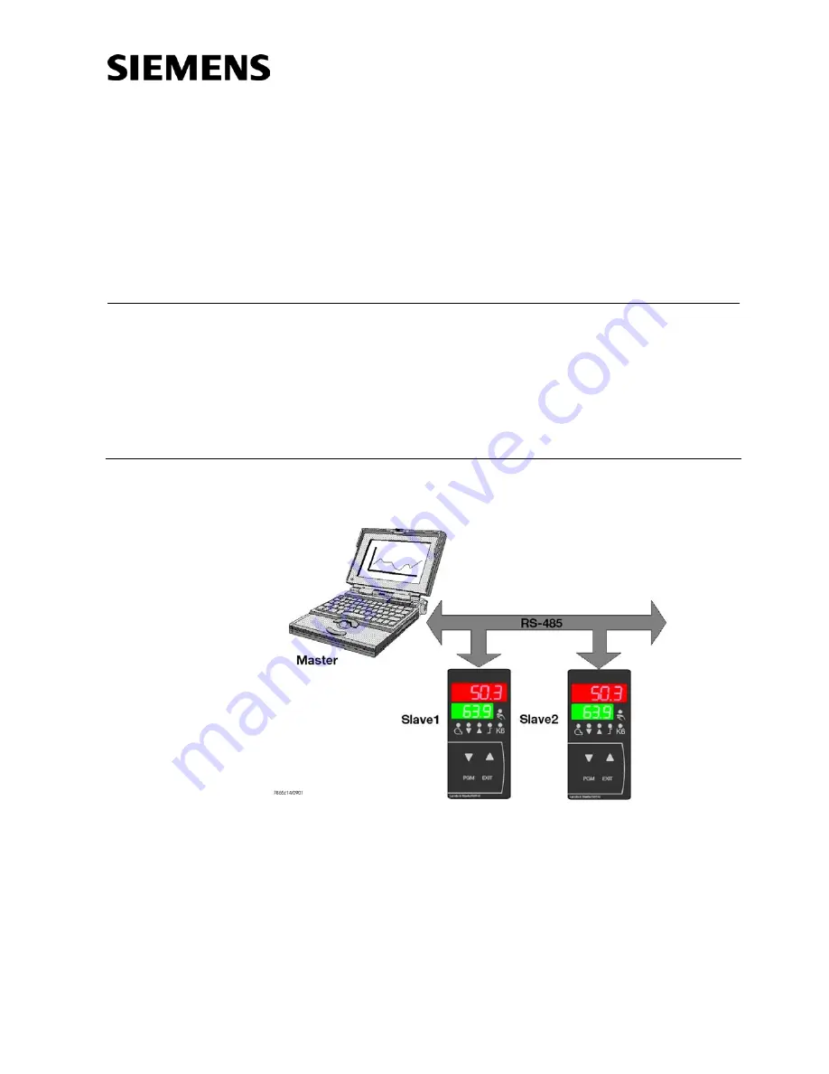
Master-slave principle

Communication between a PC (master) and a device (slave) via MOD bus is based on
the master-slave principle in the form of data query / instruction – reply.

A master computer controls the exchange of data and can address up to 99 controllers
via device addresses (slaves).

Summary of Contents for RS-485

Page 1: ...orks via MOD bus protocol Application examples Process visualization Plant control Reporting Master slave principle Communication between a PC master and a device slave via MOD bus is based on the master slave principle in the form of data query instruction reply A master computer controls the exchange of data and can address up to 99 controllers via device addresses slaves ...

Page 2: ... device addresses can be selected between 1 and 99 Device address 0 is reserved A maximum of 31 slaves can be addressed via the RS 422 RS 485 interface There are 2 choices of data exchange Query Data query instructions delivered by the master to a slave via the re spective device address The addressed slave responds Broadcast Master instructions to all slaves via device address 0 The addressed sla...

Page 3: ... 8 data bits no parity bit and 1 stop bit the character transmis sion time is calculated as follows Character transmission time ms 1000 9 bits Baud rate Data query by the master Transmission time n characters 1000 x bits Baud rate Identification of end of data query 3 characters 1000 x bits Baud rate Handling of data query by the slave 250 ms Reply by the slave Transmission time n characters 1000 ...

Page 4: ... the receiving mode This time must be observed by the master before it makes a new data query It must always be maintained even if the new data query is sent to some other device t2 20 ms Communication during the slave s internal handling time The master is not allowed to make any data queries during the slave s internal handling time Data queries made during that period of time will be ignored by...

Page 5: ...ication of transmission errors Fault handling 3 different error codes are used 1 Invalid function 2 Invalid parameter address 8 Write access to parameter rejected Slave address Function XX OR 80 h Error code Checksum CRC16 1 byte 1 byte 1 byte 2 bytes The function code is OR linked with 0 x 80 that is the MSB most significant bit will be set to 1 Data query 01 02 00 70 00 04 CRC16 Reply 01 82 01 C...

Page 6: ...CRC if flag to the right 1 then CRC CRC XOR 0xA001 else while not all ByteOfMessage edited The low byte of the checksum will be transmitted first Data query Reading 2 words from address 6 CRC16 0x24A0 0B 03 00 06 00 02 A0 24 CRC16 Reply CRC16 0x6105 0B 03 04 00 00 42 C8 61 05 Word 1 Word 2 CRC16 The following functions for the device will be available Function number Function 0x03 0x04 Reading n w...

Page 7: ... 0B 03 08 0000 42C8 0000 4316 CRC16 Setpoint 1 100 Setpoint 2 150 Writing 1 word With the Wordwriting function the data blocks for instruction and reply are identical Slave address Function 0x06 Word address Word value Checksum CRC16 1 byte 1 byte 2 bytes 2 bytes 2 bytes Slave address Function 0x06 Word address Word value Checksum CRC16 1 byte 1 byte 2 bytes 2 bytes 2 bytes Write limit value limit...

Page 8: ...tions apply under the condition that the master works with the IEEE 754 format Before transmitting a value the bytes must be exchanged in a way that the order corresponds to the presentation for the MOD bus see illustration below M 23 bit normalized mantissa E exponent complement to base 2 S Sign bit 1 negative 0 positive MOD Bus Master Read Write MMMMMMMM MMMMMMMM SEEEEEEE EMMMMMMM EMMMMMMM SEEEE...

Page 9: ...isplacement room temperature 90 90 0 Address Data type Access Parameter Value range Default value 0x0024 char 4 R W C111 9030 0x0026 char 4 R W C112 0010 0x0028 char 4 R W C113 0110 0x002A char 4 R W C000 0000 0x002C float R W SCL Normalization start value Input 1 1999 9999 0 0x002E float R W SCH Normalization end value Input 1 1999 9999 100 0x0030 float R W SCL2 Normalization start value Input 2 ...

Page 10: ...0502 float R W RHYS1 Switch on threshold REMOTE 0 1999 HYS1 0x0504 float R W RHYS2 Switch off threshold bottom REMOTE 0 RHYS3 HYS2 0x0506 float R W RHYS3 Switch off threshold top REMOTE 0 9999 HYS3 0x0508 float R W SPR Setpoint REMOTE SPL SPH SP1 0x050A word R W RK1 Burner control remote operation 0 1 0 0x050B word R W RK2 Relay K2 remote operation 0 1 0 0x050C word R W RK3 Relay K3 remote operati...

Page 11: ...11 Second setpoint active B12 Measured value range crossing input 1 B13 Measured value range crossing input 2 B14 Measured value range crossing input 3 B15 Reserved 0x0201 word R O Binary signal and hardware identification B15 B14 B13 B12 B11 B10 B9 B8 B7 B6 B5 B4 B3 B2 B1 B0 B15 Reserved B0 Operating mode 2 stage active B14 Interface present B1 Manual operation active B13 Analog output present B2...

Page 12: ...troller ON 0 OFF 1 in operating modes REMOTE SETPOINT and FULLY REMOTE 0 RSTEP Number of control cycles opening closing FULLY REMOTE 0 RK1 Release of burner FULLY REMOTE 0 RK2 Controlling element opens FULLY REMOTE 0 RK3 Controlling element closes FULLY REMOTE 0 RK6 Value of K6 in operating modes SETPOINT REMOTE and FULLY REMOTE 0 RY Degree of modulation for the analog output FULLY REMOTE in 0 Con...

Page 13: ...s the con trolling element to travel to the fully closed position The controller terminates manual operation analog safety shutdown Self optimization is not possible in this operating mode The management system controls contact RK6 relay K6 The RWF40 monitors cyclic bus communication via the Dtt parameter bus detec tion timer Operating mode FULLY REMOTE is active as long as the bus calls within th...

Page 14: ...rol time has elapsed the RWF40 ascertains the direction of rotation requested by the command If the direction of rota tion does not change the control time will immediately be replaced by the new value If the direction of rotation must be reversed the controlled output will be dactivated and for the next scanning cycle the appropriate control time is used time contact interval If simultaneously wi...

Reviews: