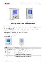


POWERS® Controls
Technical Instructions
Document No. A6V11435226
May 9, 2019
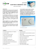
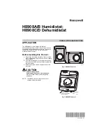
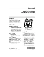
134-1861 Humidistat
Siemens Industry, Inc.
Part No 24-8466-00036 Rev. A
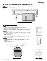
Description
The 134-1861 Humidistat controls humidifying and/or dehumidifying equipment. Typical
uses include the control of humidity by ventilation, air conditioning, humidifiers, and
dehumidifiers in residential, commercial, and industrial installations.
This humidistat has Single-Pole/Double-Throw (SPDT) snap-acting contacts rated to
switch 1/4 hp motors. It has a wide setpoint range of 0 to 70% Relative Humidity (RH), as
well as “off” dial positions for humidification and dehumidification. The differential of the
134-1861 is fixed at approximately 6% RH.
Features
•
Human Hair Sensing Element
– Provides stable, accurate measurement.
•
1/4 HP (6A) Rated Contacts
– Permit direct operation of many fans in commercial
applications.
•
High/low Adjustable Knob Range Stops
– Allow adjustments within a desired range.
•
Enclosed Pennswitch
– Provides dust protection for contacts.
•
Mounting Plate
– Allows easy mounting and wiring without removing the cover.
Product Number
134-1861
Accessories
Concealed Adjustment Faceplate, Vertical Mounting
134-034
Aluminum Guard
134-117
Warning/Caution Notations
WARNING:
Personal injury or loss of life may occur if a procedure is not
performed as specified.
CAUTION:
Equipment damage or loss of data may occur if the user
does not follow a procedure as specified