background image

Siemens 

Siemens 

Siemens 

Siemens 

Siemens Industry

Industry

Industry

Industry

Industry,,,,, Inc.

 Inc.

 Inc.

 Inc.

 Inc.

Building 

Building 

Building 

Building 

Building T

TT

TTec

ec

ec

ec

echnologies Di

hnologies Di

hnologies Di

hnologies Di

hnologies Division

vision

vision

vision

vision

P/N 315-050217-4

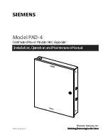
Installation, Operation and Maintenance Manual
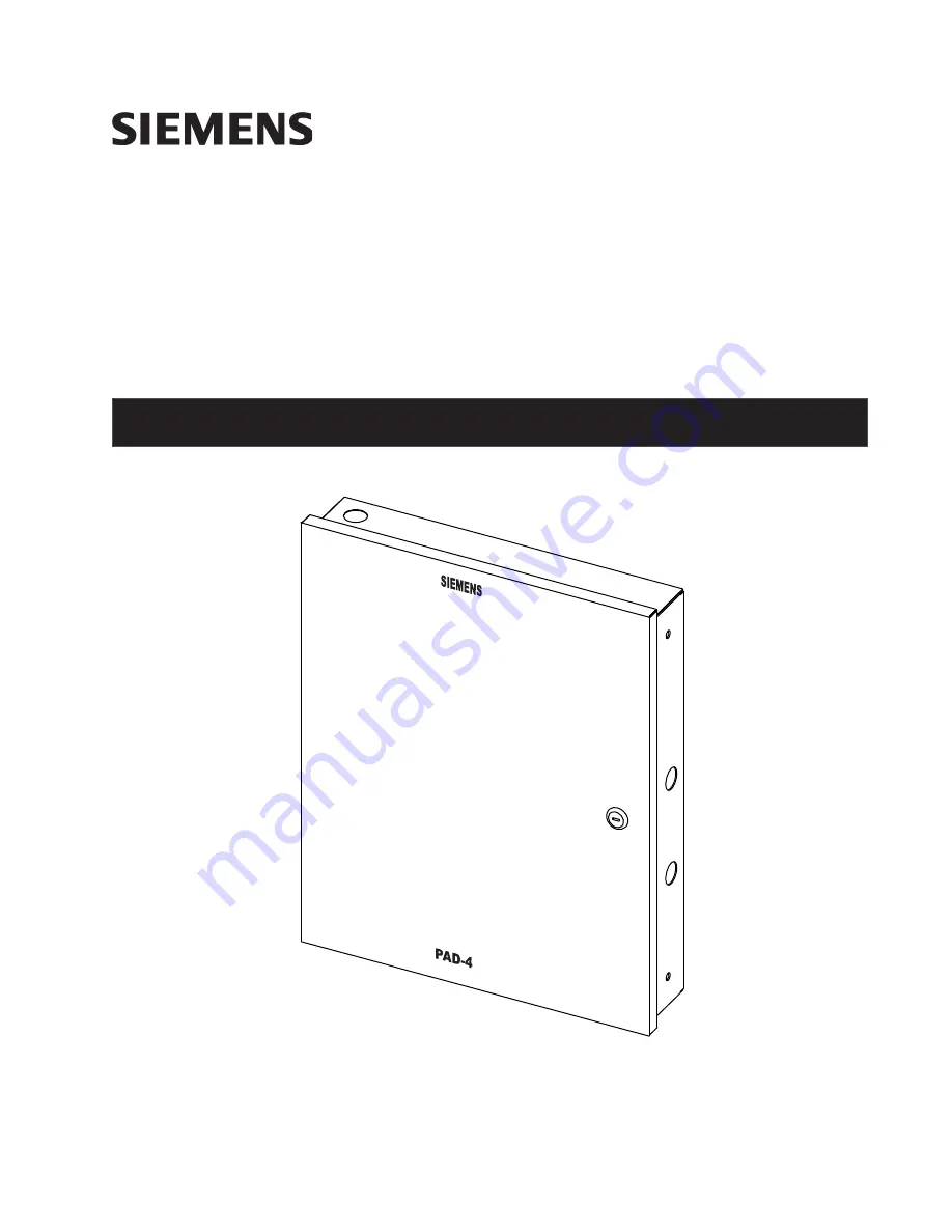
Model PAD-4

Distributed Power Module NAC Expander

Summary of Contents for PAD-4

Page 1: ...c Inc Inc Inc Building Building Building Building BuildingT T T T Tec ec ec ec echnologies Di hnologies Di hnologies Di hnologies Di hnologies Division vision vision vision vision P N 315 050217 4 Installation Operation and Maintenance Manual Model PAD 4 Distributed Power Module NAC Expander ...

Page 2: ...sult in additional site specific preventive action to ensure that the building comfort fire safety security management or physical security system for your site are operated in a secure manner These measures may include but are not limited to separating networks physically protecting system components user awareness programs defense in depth etc For additional information on building technology se...

Page 3: ...7 AC Fail Relay 16 2 7 Ground Fault Detection Enable Disable 17 2 8 Input Emulation 17 3 CONNECTION TO CONTROL UNITS 19 4 SAMPLE APPLICATIONS 33 4 1 Notification Appliance Power Applications 33 4 2 Door Holder Applications 38 5 PROGRAMMING 39 5 1 Dip Switch Settings 39 5 1 1 Selecting the Input Output Configuration 40 5 1 2 Setting the Auxiliary Output 41 5 1 3 Setting the Input s NAC Control 41 5...

Page 4: ...functioning Fire Alarm Signaling System NFPA 70 National Electrical Code NFPA 72 National Fire Alarm Code NFPA 101 Life Safety Code C22 1 Part 1 Canadian Electrical Code ULC S524 Installation of Fire Alarm Systems Other Standards Contact the authority having jurisdiction for other standards that may apply For Publications contact National Fire Protection Association Batterymarch Park Quincy MA 022...

Page 5: ...indicate trouble The fault does not affect input 2 If input 1 controls outputs 1 and 2 and input 2 controls outputs 3 and 4 a fault condition on output 3 or 4 will cause input 2 to indicate trouble The fault does not affect input 1 Once the PAD 4 s inputs and outputs are activated the fire alarm control unit will not be able to sense trouble conditions through its notification appliance circuit co...

Page 6: ...it for charging sealed lead acid batteries The unit also supervises for no and low battery conditions Battery Cutoff In order to protect the batteries when AC fails the battery voltage is constantly monitored and if it drops below 20 4V all PAD 4 power will be cut off Power will be restored when AC is restored Ground Fault Detection The PAD 4 monitors for ground faults to the output wiring When de...

Page 7: ... 3 0A per circuit 6 0A or 9 0A depending on external power supply total for NACs and auxiliary power Four Class B Style Y circuits or two Class A Style Z circuits Two additional Class A Style Z circuits are available when the PAD 4 CLSA module is installed Power limited Supervised Maximum Standby Current 1 0mA Maximum Ripple 100mVAC Maximum Line Resistance 3 0 ohms 3 0 amps 3 7 ohms 2 5 amps 4 7 o...

Page 8: ...4 PAD 4 Installation Operation and Maintenance Manual This page is left intentionally blank ...

Page 9: ...or other accessory not connected through a protective device or a circuit designed for remote connection must be within the same room and connected through electrical conduit Installation is to be done only by qualified personnel who have thoroughly read and understood these instructions When mounting the enclosure on interior walls use appropriate screw anchors in plaster When mounting on concret...

Page 10: ... from power limited wiring A separation must be maintained with high voltage and non power limited wiring running in separate conduit openings from power wiring To avoid induced noise transfer of electrical energy from one wire to another keep input wiring isolated from high current output and power limited wiring Improper wiring installa tion may cause improper operation Avoid pulling one multi c...

Page 11: ...n n o C o N 4 1 B T B 1 C A N t u p t u O 1 C A N x a m A 3 C D V 4 2 n o i t a c i l p p A l a i c e p S t u p t u o h c a e h g u o h t n e v E e h t s p m a 3 r o f d e t a r s i m o r f w a r d t n e r r u c l a t o t d n a s t u p t u o C A N 4 e h t r e w o p y r a i l i x u a e h t d e e c x e t o n t s u m t u p t u o 1 U 1 1 0 2 P F r o f s p m a 6 r o y l p p u s r e w o p W 0 7 1 1 U 2 ...

Page 12: ... you are using a Siemens control unit see Section 3 for connections TB11 1 1 2 1 1 1 TB12 TB13 TB14 TB15 NAC3B NAC4B NAC2A _ _ NAC1B NAC2B NAC1A _ _ J4 NC COM NO NC COM 2 2 1 J5 1 1 1 TB16 J8 AUX PWR SUPPLY _ J7 P1 J2 S2 JP7 DS7 BAT DS5 AUX PS DS8 PWR DS6 DS1 OUT1 DS2 OUT2 DS3 OUT3 DS4 OUT4 J9 TB10 J10 J12 J14 J13 J11 RESET 10 9 8 7 6 5 4 3 2 1 ON S1 J3 P2 SERVICE PORT J6 J16 NOT USED TROUBLE 1 B ...

Page 13: ...2 14 AWG WIRE FROM GROUND LUG TO FP2011 U1 GROUND LUG IN PAD 4 ENCL TO CONNECT GROUND WIRE FROM AC MAINS CAUTION INSTALL PLASTIC GUARD ON AC MAINS L N G Figure 2 6a AC Wiring to FP2011 U1 FP2012 U1 BLACK H WHITE N GREEN G AC MAINS SUPERVISED NON POWER LIMITED 12 14 AWG MIN CAUTION INSTALL PLASTIC GUARDS ON AC MAINS H N G USER SUPPLIED 12 14 AWG WIRE FROM GROUND LUG TO FP2012 U1 GROUND LUG IN PAD 4...

Page 14: ...NING Brownout PSSI GND 24V 170W J3 300W 170W J3 300W Figure 2 7a Wiring from FP2011 U1 Power Supply to PAD 4 MB FP2012 U1 H N G SEE FIGURE 2 6b FOR WIRING 1 2 3 4 TB10 PAD 4 MB Brownout PSSI GND 24V 300W J3 300W 170W J3 170W Figure 2 7b Wiring from FP2012 U1 Power Supply to PAD 4 MB NOTE 1 Power Supply includes a cable connection that is not detachable 2 Select 300W operation using jumper on J3 NO...

Page 15: ...ve battery terminal 6 Connect jumper wire from the positive side of battery 1 to the negative side of battery 2 When disconnecting the battery remove the quick disconnects from the jumper wire the black battery wire and the red battery wire in that order The battery set is protected by a 10 20 amp 32VDC replaceable AUTO FUSE 2 2 E L B A T S N O I T C E N N O C Y R E T T A B 4 D A P l a n i m r e T...

Page 16: ...g steps and diagrams explain how to connect two PAD 4 boards to a single battery set 1 Install a battery connection splitter see Figure 2 10 to the positive and negative terminals on the battery set If the battery set contains two 12 volt batteries to be wired in series install one splitter on the positive terminal of battery 1 and the other to the negative terminal of the battery 2 2 Connect the ...

Page 17: ...n to enable notification input supervision Note MIN 22 AWG MAX 12 AWG TB11 1 1 2 1 1 1 TB12 TB13 TB14 TB15 NAC3B NAC4B NAC2A _ _ NAC1B NAC2B NAC1A _ _ NC COM NO NC COM 2 2 1 1 1 1 TB16 AUX PWR SUPPLY _ 24VDC VFW 7mA MAX SUPERVISED BY FIRE ALARM CONTROL UNIT POWER LIMITED CLASS B STYLE Y POLARITY SHOWN IN ACTIVATED CONDITION NOTIFICATION OUTPUT FROM FIRE PANEL EOL SEE CONTROL UNIT INSTALLATION INST...

Page 18: ...nit to the PAD 4 board Pay close attention to the polarities when wiring the unit and follow these requirements When wiring to terminal 1 you must use two separate wires Do not loop a single wire or twist two conductor wires together Do not use notification appliances on Class A Style Z circuits connected for input The PAD 4 will detect voltage across the input circuits but is not designed to pass...

Page 19: ...pical application of the trouble relay is to connect the PAD 4 normally closed N C contacts in series with an EOL of a spare IDC or NAC or monitor input from a fire alarm control unit This will cause a trouble on the fire alarm control unit when the PAD 4 opens its trouble contacts For AC Fail reporting refer to Section 5 1 4 for configuration and response times Note The N C contact is the relay c...

Page 20: ...of AC fail at the protected premises 3 Program HTRI S 2 as Trouble causing which will cause the DACT to signal for all common troubles including AC fail with reporting delay 2 For Canadian Installations Program HTRI S 1 as Trouble causing which will cause the DACT to signal and will also cause a local visual and audible signal at the protected premises Program the DACT to send a Primary Power Fail...

Page 21: ...e location of this jumper If the PAD 4 is configured to monitor a switch such as a relay then the fire alarm control unit will not be able to receive trouble conditions through its notification appliance circuit connected to the PAD 4 input circuits Use the PAD 4 trouble relay when it is necessary to monitor trouble conditions Refer to Figure 3 8 TB11 TB12 1 1 1 2 2 2 1 1 COM NC INPUT 1 INPUT 2 Fi...

Page 22: ...18 PAD 4 Installation Operation and Maintenance Manual This page is left intentionally blank ...

Page 23: ...B NAC2B NAC1A _ _ NCCOMNO NC COM 2 2 1 1 1 1 TB16 AUX PWR SUPPLY _ 24K 1 2W PART NO 140 034677 DO NOT USE DO NOT USE DO NOT USE PAD 4 NOTE 3 OHM MAX TOTAL LINE RESISTANCE OF NOTIFICATION APPLIANCE CIRCUIT CONNECTING WIRE 2 2K 1 2W EOL P N 140 820380 SEE CONTROL UNIT INSTALLATION INSTRUCTIONS SMB 2 MMB 2 MMB 3 TB5 4 TB5 3 TB5 2 TB5 1 TB7 4 TB7 3 TB7 2 TB7 1 CLASS B STYLE Y SUPERVISED NOTIFICATION C...

Page 24: ... 2W PART NO 140 034677 TB1 TB2 TB3 or TB4 1 2 3 4 5 6 INPUT 1 INPUT 2 TB11 1 1 2 1 1 1 TB12 TB13 TB14 TB15 NAC3B NAC4B NAC2A _ _ NAC1B NAC2B NAC1A _ _ NCCOMNO NC COM 2 2 1 1 1 1 TB16 AUX PWR SUPPLY _ 24K 1 2W PART NO 140 034677 DO NOT USE DO NOT USE DO NOT USE PAD 4 10K 1 2W EOL P N 140 820396 SEE CONTROL UNIT INSTALLATION INSTRUCTIONS CLASS B SUPERVISED NOTIFICATION CIRCUITS 24K 1 2W PART NO 140 ...

Page 25: ...SE DO NOT USE DO NOT USE PAD 4 5 6K 1 2W EOL P N 140 112166 SEE CONTROL UNIT INSTALLATION INSTRUCTIONS CP 35 CLASS B SUPERVISED NOTIFICATION CIRCUITS 24K 1 2W PART NO 140 034677 NOTE 3 OHM MAX TOTAL LINE RESISTANCE OF NOTIFICATION APPLIANCE CIRCUIT CONNECTING WIRE 31 32 33 34 35 36 NAC3B NAC4B NAC2A NAC1B NAC2B NAC1A INPUT 1 INPUT 2 Figure 3 4 Connection to CP 35 UL Installations Only ...

Page 26: ... LINE RESISTANCE OF NOTIFICATION APPLIANCE CIRCUIT CONNECTING WIRE AE 30U CP 35 CP 35 1 2 3 4 5 6 37 38 36 INPUT POWER ACTUATION INPUT 5 6K 1 2W EOL P N 140 112166 SEE CONTROL UNIT INSTALLATION INSTRUCTIONS 24K 1 2W PART NO 140 034677 CLASS B SUPERVISED NOTIFICATION CIRCUITS 24K 1 2W PART NO 140 034677 NAC3B NAC4B NAC2A NAC1B NAC2B NAC1A INPUT 1 INPUT 2 Figure 3 5 Connection to AE 30U UL Installat...

Page 27: ...E PAD 4 5 6K 1 2W EOL P N 140 112166 CLASS A SUPERVISED NOTIFICATION CIRCUITS NOTE 3 OHM MAX TOTAL LINE RESISTANCE OF NOTIFICATION APPLIANCE CIRCUIT CONNECTING WIRE AA 30U CP 35 CP 35 1 2 3 4 5 6 37 38 36 INPUT POWER ACTUATION INPUT 7 8 NAC3B NAC4B NAC2A NAC1B NAC2B NAC1A INPUT 1 INPUT 2 POLARITY SHOWN IN SUPERVISORY CONDITION Figure 3 6 Connection to AA 30U UL Installations Only ...

Page 28: ...V 12mA ACTIVATED 1 5A MAX ICP B6 PROGRAM PLUG TB2 TB1 6 6 5 5 4 4 3 3 2 2 1 1 ANALOG LOOP CONNECTION SUPERVISED JP2 JP1 EARTH SHIELD TB11 1 1 2 1 1 1 TB12 TB13 TB14 TB15 _ _ _ _ NCCOMNO NC COM 2 2 1 1 1 1 TB16 AUX PWR SUPPLY _ 24K 1 2W PART NO 140 034677 DO NOT USE DO NOT USE DO NOT USE PAD 4 15K W EOL P N 140 820400 SEE CONTROL UNIT INSTALLATION INSTRUCTIONS CLASS B STYLE Y SUPERVISED NOTIFICATIO...

Page 29: ...OOP HTRI R 1 2 3 4 5 8 7 6 TO EARTH GROUND HTRI R 1 2 3 4 5 8 7 6 TO INPUT 1 TO INPUT 2 TB11 1 1 2 1 1 1 TB12 TB13 NCCOMNO NC COM 2 2 1 J13 J11 PNL SW 3 2 1 J12 J14 PNL SW 3 2 1 PNL SW 3 2 1 PNL SW 3 2 1 PNL SW NAC3B NAC4B NAC2A NAC1B NAC2B NAC1A DO NOT USE DO NOT USE INPUT 1 INPUT 2 TO EARTH GROUND Figure 3 8 Connection to TRI R HTRI R 8704 UL and ULC Installations NOTES 1 All wiring must be in a...

Page 30: ...2V FILTERED FULL WAVE RECTIFIED DC INPUT RATED 18 8 28 2 VDC SUPV 30mA ACTIVATED 1 5A MAX TB1 ON BACK SIDE TB2 ON BACK SIDE 6 5 4 3 2 1 1 2 3 4 5 6 PROGRAMMING POINTS TB11 1 1 2 1 1 1 TB12 TB13 TB14 TB15 _ _ _ _ NCCOMNO NC COM 2 2 1 1 1 1 TB16 AUX PWR SUPPLY _ 24K 1 2W PART NO 140 034677 DO NOT USE DO NOT USE DO NOT USE PAD 4 24K 1W EOL P N 140 033771 SEE CONTROL UNIT INSTALLATION INSTRUCTIONS CLA...

Page 31: ...X PWR SUPPLY _ DO NOT USE DO NOT USE DO NOT USE PAD 4 EOL 24K 1 2W 5 P N 140 SEE CONTROL UNIT INSTALLATION INSTRUCTIONS 034677 1 1 2 2 3 3 4 4 TB12 TB13 FS 250 MPC 6000 MPC 7000 NAC3B NAC4B NAC2A NAC1B NAC2B NAC1A INPUT 1 INPUT 2 POLARITY SHOWN IN ACTIVATED STATE Figure 3 10 Connection to FS 250 and MPC 6000 7000 UL Installations Only ...

Page 32: ... STYLE Y SUPERVISED NOTIFICATION CIRCUITS 24K 1 2W PART NO 140 034677 POLARIZED NOTIFICATION APPLIANCES CLASS B STYLE Y ZONE 2 24K 1W 5 ZONE 4 CLASS B STYLE Y 24K 1W 5 ZONE 4 INPUT ZONE 1 INPUT ZONE 2 INPUT ZONE 3 INPUT ONE SLOT OF CC 5 17 18 19 20 21 22 23 24 1 2 3 4 5 6 7 8 9 10 11 12 13 14 15 16 NC NC NC NC NC NC NAC3B NAC4B NAC2A NAC1B NAC2B NAC1A INPUT 1 INPUT 2 Figure 3 11 Connection to ZIC ...

Page 33: ...UPERVISED NOTIFICATION CIRCUITS 24K 1 2W PART NO 140 034677 ZONE 8 CLASS B STYLE Y 24K 1W 5 ZONE 7 8 INPUT ZONE 1 2 INPUT ZONE 3 4 INPUT ZONE 5 6 INPUT ONE SLOT OF CC 5 17 18 19 20 21 22 23 24 1 2 3 4 5 6 7 8 9 10 11 12 13 14 15 16 ZONE 7 24K 1W 5 ZONE 5 24K 1W 5 24K 1W 5 ZONE 6 ZONE 2 24K 1W 5 24K 1W 5 24K 1W 5 ZONE 4 ZONE 3 NAC3B NAC4B NAC2A NAC1B NAC2B NAC1A INPUT 1 INPUT 2 Figure 3 12 Connecti...

Page 34: ...1 1 TB16 AUX PWR SUPPLY _ 24K 1 2W PART NO 140 034677 DO NOT USE DO NOT USE DO NOT USE PAD 4 NOTE 3 OHM MAX TOTAL LINE RESISTANCE OF NOTIFICATION APPLIANCE CIRCUIT CONNECTING WIRE 2 4K 1 2W EOL SEE CONTROL UNIT INSTALLATION INSTRUCTIONS FC2025 FC2050 CLASS B STYLE Y SUPERVISED NOTIFICATION CIRCUITS 24K 1 2W PART NO 140 034677 INPUT 1 INPUT 2 NAC1 1 NAC1 1 NAC1 2 NAC1 2 X601 4 3 2 1 NAC1 1 NAC1 1 N...

Page 35: ...E DO NOT USE DO NOT USE PAD 4 NOTE 3 OHM MAX TOTAL LINE RESISTANCE OF NOTIFICATION APPLIANCE CIRCUIT CONNECTING WIRE 2 4K 1 2W EOL SEE CONTROL UNIT INSTALLATION INSTRUCTIONS FC922 FC924 CLASS B STYLE Y SUPERVISED NOTIFICATION CIRCUITS 24K 1 2W PART NO 140 034677 INPUT 1 INPUT 2 NAC1 1 NAC1 1 NAC1 2 NAC1 2 X601 4 3 2 1 NAC1 1 NAC1 1 NAC1 2 NAC1 2 X601 4 3 2 1 Figure 3 14 Connection to FC922 FC924 U...

Page 36: ...AC1A _ _ NCCOMNO NC COM 2 2 1 1 1 1 TB16 AUX PWR SUPPLY _ 24K 1 2W PART NO 140 034677 DO NOT USE DO NOT USE DO NOT USE PAD 4 24K 1 2W EOL SEE CONTROL UNIT INSTALLATION INSTRUCTIONS CLASS B SUPERVISED NOTIFICATION CIRCUITS 24K 1 2W PART NO 140 034677 NOTE 3 OHM MAX TOTAL LINE RESISTANCE OF NOTIFICATION APPLIANCE CIRCUIT CONNECTING WIRE FC2005 FC901 N_AN N_AP N_BN N_BP NAC INPUT 1 INPUT 2 ...

Page 37: ...uit Input 1 Fire Control Unit PAD 4 24 VDC O u t p u t 1 O u t p u t 2 O u t p u t 3 O u t p u t 4 1 2 3 S1 ON Figure 4 1 Input 1 Activates All Four Outputs and Input 2 Is Not Used Notification Appliance Circuit Input 1 Fire Control Unit PAD 4 O u t p u t 1 O u t p u t 2 O u t p u t 3 O u t p u t 4 Sync Horns Strobes Input 2 24 VDC 1 2 3 S1 ON Figure 4 2 Input 1 Activates All Four Outputs and Inpu...

Page 38: ...Unit Notification Appliance Circuit Notification Appliance Circuit Input 1 Input 1 O u t p u t 1 O u t p u t 2 O u t p u t 3 O u t p u t 4 O u t p u t 1 O u t p u t 2 O u t p u t 3 O u t p u t 4 PAD 4 PAD 4 24 VDC 1 2 3 S1 ON 24 VDC 1 2 3 S1 ON NOTE Only the appliances connected to the same PAD 4 will operate synchronously when the output circuits of the PAD 4 are set to synchronization mode The a...

Page 39: ...D 4 Input 1 O u t p u t 1 O u t p u t 2 O u t p u t 3 Output 4 PAD 4 O u t p u t 1 O u t p u t 2 O u t p u t 3 O u t p u t 4 Output 4 Input 1 Input 1 PAD 4 O u t p u t 1 O u t p u t 2 O u t p u t 3 24 VDC 1 2 3 S1 ON 24 VDC 1 2 3 S1 ON 24 VDC 1 2 3 S1 ON Figure 4 5 One Control Panel Activating Three PAD 4s ...

Page 40: ...t 4 O u t p u t 2 O u t p u t 3 Outputs Active When Fire Panel s Notification Circuit 1 Activates Outputs Active When Fire Panel s Notification Circuit 2 Activates 24 VDC 24 VDC 24 VDC 1 2 3 S1 ON 1 2 3 S1 ON 1 2 3 S1 ON NOTE Only the appliances connected to the same PAD 4 will operate synchronously when the output circuits of the PAD 4 are set to synchronization mode The appliances connected to a...

Page 41: ... ZONE CAUTION FOR SYSTEM SUPERVISION BREAK WIRE RUN TO PROVIDE SUPERVISION OF CONNECTION DO NOT USE LOOPED WIRE UNDER TERMINALS 1 1 NC COM 1 1 NC COM NOTE Only the appliances connected to the same PAD 4 will operate synchronously when the output circuits of the PAD 4 are set to synchronization mode The appliances connected to a different PAD 4 will not operate synchronously Figure 4 7 Multiple PAD...

Page 42: ...series with the auxiliary power to the door holders The circuit shown in Figure 4 8 will provide up to 3 amps of door holder current The power in this example is released when AC power is off for 30 seconds or more or when the relay from the fire alarm control unit opens See Section 1 1 for a description of the auxiliary power options and Section 5 1 2 for information on choosing the options NOTE ...

Page 43: ...ttings only when reset If you change these switch settings you must push S2 reset switch to recognize the new DIP switch settings ON 10 9 8 7 6 5 4 3 2 1 S E I T R A P D E V L O V N I R E H T O D N A N O I T C I D S I R U J G N I V A H S E I T I R O H T U A S R E L L A T S N I S R E S U O T E C I T O N d r a d n a t S e h t n i s t n e m e r i u q e r e h t h t i w y l p m o c o t t c u d o r p e ...

Page 44: ... Input 2 used to control silencing of Sync horns 1A 4A Switch 1 Switch 2 ON Switch 3 ON Input 1 controls outputs 1A and 2A as Class A Input 2 OFF controls outputs 3A and 4A as Class A WITH PAD 4 CLSA BOARD ULC INSTALLATION ONLY Switch 1 ON Switch 2 ON Switch 3 ON Input 1 controls outputs 1A 2A and 3A Class A Input 2 controls output 4A Class A Switch 1 OFF Switch 2 OFF Switch 3 ON Input 1 controls ...

Page 45: ... Input Steady Output Temporal Operation Output Sync Strobe Horn Operation Output Carbon Monoxide CO Alarm Figure 5 4 Master Input Output Relationship 9 10 8 7 6 5 4 ON OFF Switch 5 OFF Switch 6 OFF Slave Operation Input 1 s outputs will follow the input pattern steady in coded march time temporal or Sync Switch 5 ON Switch 6 OFF Master Temporal Operation Input 1 s outputs will be temporal when the...

Page 46: ... OFF Switch 10 ON AC Power Fail reporting will be delayed 60 minutes Switch 9 ON Switch 10 ON AC Power Fail reporting will be delayed 180 minutes 9 10 8 7 6 9 10 8 7 6 9 10 8 7 6 If this option is chosen the PAD 4 must always be monitored via the AC Fail relay Figure 5 6 Setting DIP Switch 9 and 10 5 2 JUMPER SETTINGS Factory settings are shown See Figure 2 5 for the location of these jumpers Note...

Page 47: ...ection provides reference for the following topics Wire selection guides Battery size calculations 6 1 WIRE SELECTION GUIDES 6 1 1 Resistance of Solid Copper Wire G W A t e e F d n a s u o h T r e p s m h O 8 1 8 0 8 6 1 8 0 5 4 1 9 1 3 2 1 1 0 2 8 e l b a T 9 r e t p a h C C E N ...

Page 48: ... r u C y l p i t l u M n m u l o c s i h T n m u l o c s i h t s e m i t t n e r r u c t i n U l o r t n o C 4 D A P 1 2 r o 1 A 4 D A P r e p A 6 6 0 0 t i n U l o r t n o C 4 D A P 2 2 r o 1 A 4 D A P r e p A 0 5 s g n i t a r r o f l a u n a m e c i v e d e h t o t r e f e r s e c n a i l p p A n o i t a c i f i t o N o N l e d o M y t i t n a u Q e c i v e D r e P t n e r r u C m r a l A y l p...

Page 49: ... n i l b e n O d e t c e t e d p o o l d e t r o h S d n o c e s r e p s k n i l b o w T d e t c e t e d t n e r r u c r e v O d n o c e s r e p s k n i l b e e r h T 5 S D S P X U A w o l l e Y t u p t u o r e w o p y r a i l i x u A D E L e l b u o r t n o d e h c t i w s r e w o p x u A n O 0 3 r e t f a f f o d e h c t i w s r e w o p x u A d n o c e s r e p k n i l b e n O r e w o p y r e t t...

Page 50: ... t e h T 3 g n i k n i l b 7 S D D E L Y R T T A B C D V 4 0 2 n a h t s s e L r e w o p t u p n i y r e t t a b w o L r e w o p t u p n i y r e t t a b o N t u p n i y r e t t a b d e t r o h S d e t r o p e r s i V 4 0 2 w o l e b e g a t l o v y r e t t a b m e t s y s r e h t o n a m o r f r e w o p y r e t t a b e s u o t d e r u g i f n o c s i 4 D A P f I l e n a p o t e l b u o r t s a e t...

Page 51: ...e Signal A sound made by one or more audible notification appliances such as bells or horns in response to the operation of an initiat ing device Authority Having Jurisdiction AHJ The organization office or individual responsible for approving equipment installations or proce dures CO Alarm Carbon Monoxide alarms Class A Circuit An initiating device or notifica tion appliance circuit in which all ...

Page 52: ...ctrical Code also published as NFPA standard 70 Notification Appliance An electrically operated appliance used to indicate the system status such as a bell horn strobe light or speaker Notification Appliance Circuit NAC A circuit to which notification appliances are connected PAD Power Auxilliary Device Power Supply That portion of the fire alarm control unit which provides the power needed to ope...

Page 53: ...ral 35 0 U MHU MCS W 315 545807 Non Sync Strobe with Strobe Only 15cd 24 0 Sync Non Sync Volume 30cd 19 0 Control Horn 75cd 12 0 110cd 9 0 Horn Strobe Yes 15cd 16 0 30cd 14 0 75cd 10 0 110cd 8 0 U MHU MCS WP 315 149460 Selectable Candela Sync Horn Only Yes Steady or Temporal 35 0 U MHU MCS W WP Non Sync Strobe with Strobe Only 15cd 24 0 Sync Non Sync Volume 30cd 19 0 Control Horn Weatherproof 75cd...

Page 54: ... 0 Non Sync Strobe 30cd 19 0 75cd 12 0 95cd 9 0 2830 315 545779 Selectable Candela Sync Horn Only Yes Steady or Temporal 35 0 Non Sync Strobe with Strobe Only 15cd 24 0 Sync Non Sync Volume 30cd 19 0 Control Horn 75cd 12 0 110cd 9 0 Horn Strobe Yes 15cd 16 0 30cd 14 0 75cd 10 0 110cd 8 0 Model Appliance Setting Instruction Part Number Maximum Number Per NAC With Maximum Rating PAD 4 3 0 Amp DC Syn...

Page 55: ......

Page 56: ...Siemens Industry Inc Building Technologies Division Florham Park NJ Siemens Canada Ltd 1577 North Service Road East Oakville Ontario L6H 0H6 Canada Document ID A6V10406110 P N 315 050217 4 ...

Reviews: