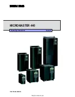
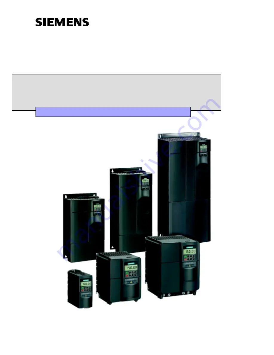
background image

MICROMASTER 440

Operating instructions

Issue A1

User Documentation

http://nicontrols.com

Summary of Contents for MICROMASTER 440 Series

Page 1: ...MICROMASTER 440 Operating instructions Issue A1 User Documentation http nicontrols com ...

Page 2: ...l automation parts and repairs based in the UK We provide a wide range of automation solutions from sourcing obsolete parts to express repairs and new part upgrades Visit nicontrols com for more information 4 4 0 1 254 6737 47 i n f o n i c o n t r o l s c o m w w w n i c o n t r o l s c o m NI N O R T H E R N INDUSTRIAL W W W N I C O N T R O L S C O M Cert No 11848 ISO 9001 2008 ...

Page 3: ...r List The Parameter List contains the description of all Parameters structured in functional order and a detailed description The Parameter list also includes a series of function plans Reference Manual The Reference Manual gives detailed information about engineering communication troubleshooting and maintenance Catalogues In the catalogue you will find all the necessary information to select an...

Page 4: ...Control Version MICROMASTER 440 04 2001 Overview 1 Installation 2 Commissioning 3 Using the MICROMASTER 440 4 System Parameters 5 Troubleshooting 6 MICROMASTER 440 Specifications 7 Available options 8 Electro Magnetic Compatibility 9 Appendices A B C D E F G H I J K L Index http nicontrols com ...

Page 5: ...s Reserved MICROMASTER is a registered trademark of Siemens Other functions not described in this document may be available However this fact shall not constitute an obligation to supply such functions with a new control or when servicing We have checked that the contents of this document correspond to the hardware and software described There may be discrepancies nevertheless and no guarantee can...

Page 6: ...r operation Operating Instructions The Operating Instructions provide detailed information for installation and operation of your MICROMASTER 440 The Operating Instructions also provide detailed descriptions of the parameters available for customizing the functions of the MICROMASTER 440 Reference Manual The Reference Manual contains in depth information on all technical issues relating to the MIC...

Page 7: ...son is someone who is familiar with the installation mounting start up and operation of the equipment and the hazards involved He or she must have the following qualifications 1 Trained and authorized to energize de energize clear ground and tag circuits and equipment in accordance with established safety procedures 2 Trained in the proper care and use of protective equipment in accordance with es...

Page 8: ...peration and maintenance procedures contained in this manual The successful and safe operation of this equipment is dependent upon its proper handling installation operation and maintenance Risk of electric shock The DC link capacitors remain charged for five minutes after power has been removed It is not permissible to open the equipment until 5 minutes after the power has been removed HP ratings...

Page 9: ... work on the device system Only permanently wired input power connections are allowed This equipment must be grounded IEC 536 Class 1 NEC and other applicable standards If a Residual Current operated protective Device RCD is to be used it must be an RCD type B Machines with a three phase power supply fitted with EMC filters must not be connected to a supply via an ELCB Earth Leakage Circuit Breake...

Page 10: ...protection in accordance with UL508C section 42 Refer to P0610 level 3 and P0335 I 2 t is ON by default Motor overload protection can also be provided using an external PTC disabled by default P0601 This equipment is suitable for use in a circuit capable of delivering not more than 10 000 symmetrical amperes rms for a maximum voltage of 230V 460V 575V when protected by a H or K type fuse see Table...

Page 11: ...Foreword International English MICROMASTER 440 Operating instructions 10 6SE6400 5CA00 0BP0 http nicontrols com ...

Page 12: ...40 45 4 1 Frequency Setpoint P1000 46 4 2 Command Sources P0700 47 4 3 OFF and braking Functions 47 4 4 Control Modes P1300 49 4 5 Faults and warnings 50 5 System Parameters 51 5 1 Introduction to MICROMASTER System Parameters 52 5 2 Parameter Overview 53 5 3 Parameter List short form 54 6 Troubleshooting 67 6 1 Troubleshooting with the Status Display Panel 68 6 2 Troubleshooting with the Basic Op...

Page 13: ... Board 99 D Removing Covers Frame Sizes B and C 100 E Removal of Covers Frame Size D and E 101 F Removal of Covers Frame Size F 102 G Removing Y Cap Link Frame Size A 103 H Removing Y Cap Link Frame Sizes B and C 104 I Removing Y Cap Link Frame Sizes D and E 105 J Removing Y Cap Link Frame Sizes F 106 K Applicable Standards 107 L List of Abbreviations 108 Index 109 http nicontrols com ...

Page 14: ...8 Figure 3 6 Changing parameters via the BOP 39 Figure 3 7 Typical Motor Rating Plate Example 41 Figure 5 1 Quick Commissioning Flowchart 51 List of Tables Table 2 1 Dimensions and Torques of MM440 all frame sizes 23 Table 3 1 Default settings for operation using the Status Display Panel 35 Table 3 2 Default settings for operation using the BOP 39 Table 6 1 Inverter conditions indicated by the LED...

Page 15: ...Table of Contents International English MICROMASTER 440 Operating instructions 14 6SE6400 5CA00 0BP0 http nicontrols com ...

Page 16: ...Overview MICROMASTER 440 Operating instructions 6SE6400 5CA00 0BP0 15 1 Overview This Chapter contains A summary of the major features of the MICROMASTER 440 range 1 1 The MICROMASTER 440 16 1 2 Features 16 http nicontrols com ...

Page 17: ...vanced motor control applications via its comprehensive functionality The MICROMASTER 440 can be used in both stand alone applications as well as being integrated into Automation Systems 1 2 Features Main Characteristics Easy to install parameterize and commission Rugged EMC design Can be operated on IT line supplies Fast repeatable response time to control signals Comprehensive range of parameter...

Page 18: ...s with programmable smoothing Closed loop control using PID Proportional Integral and Differential control loop function with auto tuning Built in braking chopper Selectable up and down ramps 4 point ramp smoothing Multi point V f characteristic parameter sets which can be switched allowing one inverter to control several alternative processes Protection characteristics Overvoltage undervoltage pr...

Page 19: ...1 Overview International English MICROMASTER 440 Operating instructions 18 6SE6400 5CA00 0BP0 http nicontrols com ...

Page 20: ...ion This Chapter contains General data relating to installation Dimensions of Inverter Wiring guidelines to minimize the effects of EMI Details concerning electrical installation 2 1 General 21 2 2 Ambient operating conditions 22 2 3 Mechanical Installation 23 2 4 Electrical Installation 25 http nicontrols com ...

Page 21: ... supply fitted with EMC filters must not be connected to a supply via an ELCB Earth Leakage Circuit Breaker EN50178 Section 5 2 11 1 The following terminals can carry dangerous voltages even if the inverter is inoperative the power supply terminals L L1 N L2 L3 the motor terminals U V W DC B DC B and DC R Always wait 5 minutes to allow the unit to discharge after switching off before carrying out ...

Page 22: ...o reforming required No preparation 1 to 2 years Apply power to the inverter for one hour before issuing the run command 1 hour 2 to 3 years Use a variable AC supply Apply 25 of input voltage for 30 minutes Increase volts to 50 for a further 30 minutes Increase volts to 75 for a further 30 minutes Increase volts to 100 for a further 30 minutes Inverter ready for run signal 2 hours 3 years and over...

Page 23: ...l the inverter in an area where it is likely to be exposed to constant vibration Electromagnetic Radiation Do not install the inverter near sources of electromagnetic radiation Atmospheric Pollution Do not install the inverter in an environment which contains atmospheric pollutants such as dust corrosive gases etc Water Take care to site the inverter away from potential water hazards e g do not in...

Page 24: ... correct use of tools and personal protective equipment PPE The mains input DC and motor terminals can carry dangerous voltages even if the inverter is inoperative wait 5 minutes to allow the unit to discharge after switching off before carrying out any installation work 4 160 mm 6 30 55 mm 0 22 Ø 4 5 mm 0 17 Ø 4 8 mm 0 19 174 mm 6 85 138 mm 5 43 Ø 5 5 mm 0 22 204 mm 8 03 174 mm 6 85 Frame Size A ...

Page 25: ...520 mm 275 mm 245 mm 4 x M8 Bolts 4 x M8 Nuts 4 x M8 Washers 3 0 Nm with washers fitted E 650 mm 275 mm 245 mm 4 x M8 Bolts 4 x M8 Nuts 4 x M8 Washers 3 0 Nm with washers fitted F 850 mm with filter 1150 mm 350 mm 300 mm 4 x M8 Bolts 4 x M8 Nuts 4 x M8 Washers 3 0 Nm with washers fitted 2 3 1 DIN Rail Mounting Frame Size A Fitting the Inverter to the DIN Rail 1 Fit the inverter to the DIN rail usi...

Page 26: ...s must be maintained if the inverters are installed on top of each other 2 4 1 General Warning The inverter must always be grounded If the inverter is not grounded correctly extremely dangerous conditions may arise within the inverter which could prove potentially fatal Operation with ungrounded IT supplies The MICROMASTER will operate from ungrounded supplies and will continue to operate if an in...

Page 27: ...ated with voltage frequency control characteristic P1300 0 2 or 3 Caution After connecting the power and motor cables to the proper terminals make sure that the covers have been replaced properly before supplying power to the unit Note Ensure that the appropriate circuit breakers fuses with the specified current rating are connected between the power supply and inverter see Tables starting on page...

Page 28: ...DC B DC W U V PE R Ground Ground L 3 L 2 L 3 L N DC DC DC V B U W PE B R Ground Ground FRAME SIZEA FRAME SIZE F FRAME SIZE B C L1 U B DC DC L2 L3 DC W V N L B R PE Ground Ground FRAME SIZE D E Ground Ground DC DC DC B B R PE L1 U L2 L3 W V N L DC B Figure 2 2 MICROMASTER 440 Connection Terminals http nicontrols com ...

Page 29: ... N L1 L2 L3 OPTIONAL FILTER Class B only MICROMASTER MOTOR U U V V W W L L1 N L2 PE PE PE SINGLE PHASE CONTACTOR FUSE L1 L2 L3 L1 L2 L3 OPTIONAL FILTER MICROMASTER MOTOR U U V V W W PE PE PE THREE PHASE TYPICAL INSTALLATION CABLE SCREENING CABLE SCREENING Figure 2 3 Motor and Power Connections http nicontrols com ...

Page 30: ...eened wires are as short as possible Separate the control cables from the power cables as much as possible using separate trunking if necessary at 90º to each other Whenever possible use screened leads for the connections to the control circuitry Ensure that the contactors in the cubicle are suppressed either with R C suppressors for AC contactors or flywheel diodes for DC contactors fitted to the...

Page 31: ...L3 L2 L1 1 1 2 5 7 7 2 3 4 3 6 Figure 2 4 Wiring Guidelines to Minimize the Effects of EMI Legend 1 Mains power input 2 Control cable 3 Motor cable to I O board 4 Footprint filter 5 Metal back plate 6 Use suitable clips to fix motor and control cable screens securely to metal back plate 7 Screen cable Note To enhance the screening of the motor and control cables the optional Gland Plate can be use...

Page 32: ...on of the front panel controls A brief description of the optional front panels available and an explanation of the operation of the Basic Operator Panel BOP An 8 step guide at the end of the Chapter which provides a simple procedure for changing parameters 3 1 Block Diagram 33 3 2 Commission Modes 34 3 3 General operation 43 http nicontrols com ...

Page 33: ...ependent limit switches mechanical interlocks etc Certain parameter settings may cause the inverter to restart automatically after an input power failure Motor parameters must be accurately configured for motor overload protection to operate correctly This equipment is capable of providing internal motor overload protection in accordance with UL508C section 42 Refer to P0610 level 3 and P0335 I 2 ...

Page 34: ...2 13 26 27 Isolated 24 V Output Isolated 0 V Output NPN PNP or OPTO ISOLATION CPU P N 29 30 COM NC 20 18 NO 19 RELAY 3 RS485 COM NC 25 23 NO 24 COM 22 NO 21 D A D A The analog input circuit can be alternatively configured to provide additional digital inputs DIN7 DIN8 as shown NOTES 1 When an analogue input is configured as a digital input the threshold values are as follows 2 AIN1 can be used wit...

Page 35: ... Ramp down time 10 s If more complex application settings are required please refer to Sections 3 2 4 1 Quick commissioning P0010 1 and 5 System Parameters Note Frequency setting the DIP switch is located on the control board underneath the I O board as shown in Figure 3 2 below The inverter is delivered as follows DIP switch 2 Off position European defaults 50 Hz kW etc On position North American...

Page 36: ...he appropriate Appendices in this manual Note The terminal layout for connecting power and control cables is shown in the photograph on the inside of the back cover of this manual 3 2 2 Commissioning with the Status Display Panel SDP The SDP is supplied with your MICROMASTER 440 Inverter as standard This panel has two LEDs on the front which indicate the operational status of the inverter With the...

Page 37: ...igital Input 6 17 P0706 15 Fixed Frequency Digital Input 7 Via AIN1 P0707 0 Inactive Digital Input 8 Via AIN2 P0708 0 Inactive 3 2 3 Basic operation with SDP With the SDP fitted the following is possible Start and stopping the motor DIN1 via external switch Reversing the motor DIN2 via external switch Fault Reset DIN3 via external switch Controlling the speed of the motor is accomplished by connec...

Page 38: ...s parameter allows a group of parameters to be selected that will enable quick commissioning Parameters such as Motor settings and Ramp settings are included At the end of the quick commissioning sequence P3900 should be selected which when set to 1 will carry out the necessary motor calculations and clear all other parameters not included in P0010 1 to the default settings This will only happen i...

Page 39: ...or Speed1 0 40000 1 min Nominal motor speed rpm from rating plate P0700 Selection of Command Source 2 on off reverse 0 Factory Setting 1 Basic Operator Panel 2 Terminal Digital Inputs P1000 Selection of Frequency Setpoint 2 0 No frequency setpoint 1 BOP frequency control 2 Analogue Setpoint P1080 Min Motor Frequency Sets minimum motor frequency 0 650Hz at which the motor will run irrespective of t...

Page 40: ...pability to store parameter information Table 3 1 shows the factory default settings for operation via the Basic Operator Panel Notes The BOP motor control functions are disabled by default To control the motor via the BOP parameter P0700 should be set to 1 and P1000 set to 1 The BOP can be fitted to and removed from the inverter whilst power is applied If the BOP has been set as the I O control P...

Page 41: ...run at the preset jog frequency The inverter stops when the button is released Pressing this button when the inverter motor is running has no effect Functions This button can be used to view additional information Pressing and holding the button for 2 seconds from any parameter during operation shows the following 1 DC link voltage indicated by d units V 2 Output current A 3 Output frequency Hz 4 ...

Page 42: ... value level 4 Press or to the required value 5 Press to confirm and store the value 6 Only the motor parameters are visible to the user Changing P1082 an indexed parameter setting maximum motor frequency Step Result on display 1 Press to access parameters 2 Press until P1082 is displayed 3 Press to access the parameter value level 4 Press to display current set value 5 Press or to the required va...

Page 43: ...g parameters with BOP 1 Press function button which causes the right hand digit to blink 2 Change the value of this digit by pressing 3 Press function button again causes the next digit to blink 4 Perform steps 2 to 4 until the required value is displayed 5 Press the to leave the parameter value changing level Note The function button may also be used to acknowledge a fault condition Motor data fo...

Page 44: ... Its advanced features include the following Multilingual clear text display Upload download of multiple parameter sets Multidrop capability to drive up to 30 inverters Please refer to the AOP Manual for details or contact your local Siemens sales office for assistance 3 3 General operation For a full description of standard and extended parameters please refer to the Parameter List Notes 1 The in...

Page 45: ...3 Commissioning International English MICROMASTER 440 Operating instructions 44 6SE6400 5CA00 0BP0 http nicontrols com ...

Page 46: ...440 which will allow the user to configure the inverter for a number of applications A brief summary of all the inverter s control modes and an introduction to the inverter s fault and warning reporting capability More detailed information can be found in the Parameter List and the Reference manual associated with the MICROMASTER 440 4 1 Frequency Setpoint P1000 46 4 2 Command Sources P0700 47 4 3...

Page 47: ...ERS operate at high voltages Certain parameter settings may cause the inverter to restart automatically after an input power failure Motor parameters must be accurately configured for motor overload protection to operate correctly This equipment is capable of providing internal motor overload protection in accordance with UL508C section 42 Refer to P0610 level 3 and P0335 I 2 t is ON by default Mo...

Page 48: ...pressing the Off button once long two seconds or twice with default settings not possible without BOP AOP OFF3 no standard setting Other settings see P0700 to P0708 Reversing the motor Default Terminal 6 DIN 2 high Other settings see P0700 to P0708 4 3 OFF and braking Functions 4 3 1 OFF1 This command produced by canceling the ON command causes the inverter to come to a standstill at the selected ...

Page 49: ...amic braking 4 3 4 DC braking DC braking is possible together with OFF1 and OFF3 A DC current is applied to stop the motor quickly and hold the shaft stationary until the end of the braking period Enable DC braking see P0701 to P0708 Set DC braking period see P1233 Set DC braking current see P1232 Set DC braking start frequency see P1234 Note If no digital input is set to DC braking and P1233 0 DC...

Page 50: ...ge in order to search for the minimum power consumption It is designed to function when the preset setpoint speed is reached V f control for textile applications P1300 5 There is no slip compensation or resonance damping The Imax controller refers to the voltage instead of frequency V f control with FCC for textile applications P1300 6 A combination of P1300 1 and P1300 5 V f control with independ...

Page 51: ...section 6 1 on page 68 for further information If the inverter is working correctly the following LED sequence is visible Green and Yellow Ready to run Green Run BOP fitted If a BOP is fitted the fault states P0947 and warnings P2110 are displayed should a fault condition occur For further details please refer to the Parameter List AOP fitted If the AOP is fitted the fault and warning codes are di...

Page 52: ...1 5 System Parameters This Chapter contains A functional overview of the parameters available for customizing your MICROMASTER MM440 Inverter A list of the parameters used 5 1 Introduction to MICROMASTER System Parameters 52 5 2 Parameter Overview 53 5 3 Parameter List short form 54 http nicontrols com ...

Page 53: ... is automatically perform if P3900 0 P0004 acts as a filter allowing access to parameters according to their functionality If an attempt is made to change a parameter that cannot be changed in this status for example cannot be changed whilst running or can only be changed in quick commissioning then will be displayed Busy Message In some cases when changing parameter values the display on the BOP ...

Page 54: ...ication P0004 21 Alarms Warnings Monitoring P0004 22 PI Controller P0004 4 Speed sensor P0004 0 no filter function allows direct access to the parameters For BOP and AOP depending on the selected access level P0004 2 P0003 1 Parameters level 1 concerning the inverter unit P0004 2 P0003 2 Parameters level 1 and 2 concerning the inverter unit P0004 2 P0003 3 Parameters level 1 2 and 3 concerning the...

Page 55: ...100 Europe North America 0 1 C Q P3900 End of quick commissioning 0 1 C Q Parameter Reset Par No Parametername Default Level WS QC P0970 Factory reset 0 1 C N Inverter Unit P0004 2 Par No Parametername Default Acc WS QC r0018 Firmware version 1 r0026 1 CO Act DC link voltage 2 r0037 2 CO Inverter temperature C 3 r0039 CO Energy consumpt meter kWh 2 P0040 Reset energy consumption meter 0 2 CT N r00...

Page 56: ... pairs 3 P0320 3 Motor magnetizing current 0 0 3 CT Q r0330 3 Rated motor slip 3 r0331 3 Rated magnetization current 3 r0332 3 Rated power factor 3 r0333 3 Rated motor torque 3 P0335 3 Motor cooling 0 2 CT Q P0340 3 Calculation of motor parameters 0 2 CT N P0341 3 Motor inertia kg m 2 0 00180 3 CUT N P0342 3 Inertia ratio total motor 1 000 3 CUT N P0344 3 Motor weight 9 4 3 CUT N r0345 3 Motor sta...

Page 57: ...igital input 2 12 2 CT N P0703 3 Function of digital input 3 9 2 CT N P0704 3 Function of digital input 4 15 2 CT N P0705 3 Function of digital input 5 15 2 CT N P0706 3 Function of digital input 6 15 2 CT N P0707 3 Function of digital input 7 0 2 CT N P0708 3 Function of digital input 8 0 2 CT N P0719 3 Selection of cmd freq setp 0 3 CT N r0720 Number of digital inputs 3 r0722 CO BO Binary input ...

Page 58: ... UP command 19 13 3 CT N P1036 3 BI Enable MOP DOWN command 19 14 3 CT N P1055 3 BI Enable JOG right 0 0 3 CT N P1056 3 BI Enable JOG left 0 0 3 CT N P1074 3 BI Disable additional setpoint 0 0 3 CUT N P1110 3 BI Inhibit neg freq setpoint 0 0 3 CT N P1113 3 BI Reverse 722 1 3 CT N P1124 3 BI Enable JOG ramp times 0 0 3 CT N P1230 3 BI Enable DC braking 0 0 3 CUT N P2103 3 BI 1 Faults acknowledgemen...

Page 59: ...aling 0 0 2 CUT N P0778 2 Value y1 of DAC scaling 0 2 CUT N P0779 2 Value x2 of DAC scaling 100 0 2 CUT N P0780 2 Value y2 of DAC scaling 20 2 CUT N P0781 2 Width of DAC deadband 0 2 CUT N Setpoint Channel and Ramp Generator P0004 10 Par No Parametername Default Acc WS QC P1000 3 Selection of frequency setpoint 2 1 CT Q P1001 3 Fixed frequency 1 0 00 2 CUT N P1002 3 Fixed frequency 2 5 00 2 CUT N ...

Page 60: ...t scaling 1 0 3 CT N P1075 3 CI Additional setpoint 0 0 3 CT N P1076 3 CI Additional setpoint scaling 1 0 3 CT N r1078 CO Total frequency setpoint 3 r1079 CO Selected frequency setpoint 3 P1080 3 Min frequency 0 00 1 CUT Q P1082 3 Max frequency 50 00 1 CT Q P1091 3 Skip frequency 1 0 00 3 CUT N P1092 3 Skip frequency 2 0 00 3 CUT N P1093 3 Skip frequency 3 0 00 3 CUT N P1094 3 Skip frequency 4 0 0...

Page 61: ...ng current 100 2 CUT N P1233 3 Duration of DC braking 0 2 CUT N P1234 3 DC braking start frequency 0 2 CUT N P1236 3 Compound braking current 0 2 CUT N P1237 Dynamic braking 0 2 CUT N P1240 3 Configuration of Vdc controller 1 3 CT N r1242 CO Switch on level of Vdc max 3 P1243 3 Dynamic factor of Vdc max 100 3 CUT N P1245 3 Switch on level kin buffering 76 3 CUT N P1247 3 Dyn factor of kinetic buff...

Page 62: ...316 3 Boost end frequency 20 0 3 CUT N P1320 3 Programmable V f freq coord 1 0 00 3 CT N P1321 3 Programmable V f volt coord 1 0 0 3 CUT N P1322 3 Programmable V f freq coord 2 0 00 3 CT N P1323 3 Programmable V f volt coord 2 0 0 3 CUT N P1324 3 Programmable V f freq coord 3 0 00 3 CT N P1325 3 Programmable V f volt coord 3 0 0 3 CUT N P1330 3 CI Voltage setpoint 0 0 3 T N P1333 3 Start frequency...

Page 63: ... torque limit 5 13 2 CUT N P1521 3 CO Lower torque limit 5 13 2 CUT N P1522 3 CI Upper torque limit 1520 0 3 T N P1523 3 CI Lower torque limit 1521 0 3 T N P1525 3 Scaling lower torque limit 100 0 3 CUT N r1526 CO Upper torque limitation 3 r1527 CO Lower torque limitation 3 P1530 3 Motoring power limitation 0 75 2 CUT N P1531 3 Regenerative power limitation 0 75 2 CUT N r1538 CO Upper torque limit...

Page 64: ...N P2013 2 USS PKW length 127 3 CUT N P2014 2 USS telegram off time 0 3 CT N r2015 8 CO PZD from BOP link USS 3 P2016 8 CI PZD to BOP link USS 52 0 3 CT N r2018 8 CO PZD from COM link USS 3 P2019 8 CI PZD to COM link USS 52 0 3 CT N r2024 2 USS error free telegrams 3 r2025 2 USS rejected telegrams 3 r2026 2 USS character frame error 3 r2027 2 USS overrun error 3 r2028 2 USS parity error 3 r2029 2 U...

Page 65: ...or freq setp 3 00 2 CUT N P2162 3 Hysteresis freq for overspeed 20 00 2 CUT N P2163 3 Entry freq for perm deviation 3 00 2 CUT N P2164 3 Hysteresis frequency deviation 3 00 3 CUT N P2165 3 Delay time permitted deviation 10 2 CUT N P2166 3 Delay time ramp up completed 10 2 CUT N P2167 3 Switch off frequency f_off 1 00 3 CUT N P2168 3 Delay time T_off 10 3 CUT N r2169 CO Act filtered frequency 2 P21...

Page 66: ...tpoint 8 70 00 2 CUT N P2209 3 Fixed PID setpoint 9 80 00 2 CUT N P2210 3 Fixed PID setpoint 10 90 00 2 CUT N P2211 3 Fixed PID setpoint 11 100 00 2 CUT N P2212 3 Fixed PID setpoint 12 110 00 2 CUT N P2213 3 Fixed PID setpoint 13 120 00 2 CUT N P2214 3 Fixed PID setpoint 14 130 00 2 CUT N P2215 3 Fixed PID setpoint 15 130 00 2 CUT N P2216 Fixed PID setpoint mode Bit 0 1 3 CT N P2217 Fixed PID setp...

Page 67: ...k 100 00 3 CUT N P2268 Min value for PID feedback 0 00 3 CUT N P2269 Gain applied to PID feedback 100 00 3 CUT N P2270 PID feedback function selector 0 3 CUT N P2271 PID tranducer type 0 2 CUT N r2272 CO PID scaled feedback 2 r2273 CO PID error 2 P2274 PID derivative time 0 000 2 CUT N P2280 PID proportional gain 3 000 2 CUT N P2285 PID integral time 0 000 2 CUT N P2291 PID output upper limit 100 ...

Page 68: ...play Panel supplied as standard with your inverter Some general information on a variety of troubleshooting measures A list of the fault codes that may appear on the display of the BOP The cause and recommended corrective action are indicated for each fault code listed 6 1 Troubleshooting with the Status Display Panel 68 6 2 Troubleshooting with the Basic Operator Panel 69 6 3 Fault messages 70 ht...

Page 69: ...ted by the LEDs on the SDP LEDs Green Yellow Priority Display Inverter Status Definitions OFF OFF 1 Mains not present OFF ON 8 Inverter fault other than those listed below ON OFF 13 Inverter running ON ON 14 Ready to run standby OFF Flashing R1 4 Fault Overcurrent Flashing R1 OFF 5 Fault Overvoltage Flashing R1 ON 7 Fault Motor Overtemperature ON Flashing R1 8 Fault Inverter Overtemperature Flashi...

Page 70: ...700 1 for BOP control Check that the setpoint is present 0 to 10V on Terminal 3 or the setpoint has been entered into the correct parameter depending upon the setpoint source P1000 See the Parameter List for further details If the motor fails to run after changing the parameters set P0010 30 then P0970 1 and press P to reset the inverter to the factory default parameter values Now use a switch bet...

Page 71: ... limits Note Higher inertia requires longer ramp times otherwise apply braking resistor Off2 F0003 UnderVoltage Main supply failed Shock load outside specified limits Check the following 1 Supply voltage P0210 must lie within limits indicated on rating plate 2 Supply must not be susceptible to temporary failures or voltage reductions Off2 F0004 Inverter Over Temperature Ventilation inadequate Fan ...

Page 72: ...ance less than 50 and greater than 500 Alarm value 6 Identified rotor time constant less than 10ms or greater than 5s Alarm value 7 Identified total leakage reactance less than 5 and greater than 50 Alarm value 8 Identified stator leakage reactance less than 25 and greater than 250 Alarm value 9 Identified rotor leakage inductance less than 25 and greater than 250 Alarm value 20 Identified IGBT on...

Page 73: ...ot work properly Replace drive Off2 F0452 Belt Failure Detected Load conditions on motor indicate belt failure or mechanical fault Check the following 1 No breakage seizure or obstruction of drive train 2 Proper operation of external speed sensor if in use 3 P0402 pulse per min at rated speed P2164 hysteresis freq deviation and P2165 delay time for permitted deviation must have correct values 4 P2...

Page 74: ...Temperature I2 T Motor overloaded Load duty cycle too high Check the following 1 P0611 motor I2 t time constant should be set to appropriate value 2 P0614 Motor I2 t overload warning level should be set to suitable level A0512 Motor temperature signal lost Wire break to motor temperature sensor If a wire breakage is be detected temperature monitoring switches over to monitoring with the motor ther...

Page 75: ...ust be match In certain cases apply braking resistor A0911 Vdc max controller active Vdc max controller is active so ramp down times will be increased automatically to keep DC link voltage r0026 within limits P2172 A0912 Vdc min controller active Vdc min controller will be activated if DC link voltage r0026 falls below minimum level P2172 The kinetic energy of the motor is used to buffer the DC li...

Page 76: ...t Check the following 1 No breakage seizure or obstruction of drive train 2 Proper operation of external speed sensor if in use 3 P0402 pulse per min at rated speed P2164 Hysteresis freq deviation and P2165 delay time for permitted deviation must have correct values 4 P2155 threshold frequency f1 P2157 threshold frequency f2 P2159 threshold frequency f3 P2174 upper torque threshold 1 P2175 lower t...

Page 77: ...6 Troubleshooting International English MICROMASTER 440 Operating instructions 76 6SE6400 5CA00 0BP0 http nicontrols com ...

Page 78: ...77 7 MICROMASTER 440 Specifications This Chapter contains In Table 7 1 the common technical data to the MICROMASTER 440 Inverters In Table 7 2 the wire sizes and terminal torques In Table 7 3 divided in several tables an overview of the specific technical data of every MICROMASTER 440 Inverter http nicontrols com ...

Page 79: ...A or B also Internal Class A filters available selected units Protection Features Undervoltage Overvoltage Ground Faults Short circuit Stall Prevention Locked Rotor Motor Overtemperature Inverter Overtemperature Input Frequency 47 to 63 Hz Setpoint Resolution 0 01Hz Digital 0 01 Hz Serial 10 bit Analogue motor potentiometer 0 1 Hz 0 1 in PID mode Output Frequency Resolution 0 01 Hz Digital 0 01 Hz...

Page 80: ...4 0 Output kVA 0 4 0 7 1 0 1 3 1 7 2 4 3 2 4 6 6 0 Output Current Max A 0 9 1 7 2 3 3 0 3 9 5 5 7 4 10 4 13 6 Input Current A 1 4 2 7 3 7 5 0 6 6 9 6 13 0 17 6 23 7 10 10 10 16 16 20 20 25 32 Recommended Fuse A 3NA3803 3NA3803 3NA3803 3NA3805 3NA3805 3NA3807 3NA3807 3NA3810 3NA3812 mm2 1 0 1 0 1 0 1 0 1 0 1 0 1 5 2 5 4 0 Input Cable Min awg 17 17 17 17 17 17 15 13 11 mm2 2 5 2 5 2 5 2 5 2 5 6 0 6 ...

Page 81: ...nt A 10 5 13 1 17 5 VT Input Current A 10 5 17 6 26 5 VT Output Cur Max A 13 6 22 0 28 0 20 25 35 Recommended Fuse A 3NA3807 3NA3810 3NA3814 mm2 1 0 2 5 4 0 Input Cable Min awg 17 0 13 0 11 0 mm2 10 0 10 0 10 0 Input Cable Max awg 7 0 7 0 7 0 mm2 1 5 4 0 4 0 Output Cable Min awg 15 0 11 0 11 0 mm2 10 0 10 0 10 0 Output Cable Max awg 7 0 7 0 7 0 kg 5 7 5 7 5 7 Weight lbs 12 5 12 5 12 5 w mm 185 0 1...

Page 82: ...NA3803 3NA3803 3NA3803 3NA3805 3NA3805 3NA3807 3NA3807 3NA3810 3NA3812 mm2 1 0 1 0 1 0 1 0 1 0 1 0 1 5 2 5 4 0 Input Cable Min awg 17 17 17 17 17 17 15 13 11 mm2 2 5 2 5 2 5 2 5 2 5 6 0 6 0 6 0 10 0 Input Cable Max awg 13 13 13 13 13 9 9 9 7 mm2 1 0 1 0 1 0 1 0 1 0 1 0 1 0 1 0 1 5 Output Cable Min awg 17 17 17 17 17 17 17 17 15 mm2 2 5 2 5 2 5 2 5 2 5 6 0 6 0 6 0 10 0 Output Cable Max awg 13 13 13...

Page 83: ...24 3NA3824 3NA3830 3NA3830 3NA3836 3NA3140 3NA3140 mm2 2 5 4 0 10 0 16 0 16 0 25 0 25 0 50 0 70 0 70 0 Input Cable Min awg 13 0 11 0 7 0 5 0 5 0 3 0 3 0 0 0 2 0 2 0 mm2 10 0 10 0 35 0 35 0 35 0 35 0 35 0 150 0 150 0 150 0 Input Cable Max awg 7 0 7 0 2 0 2 0 2 0 2 0 2 0 5 0 5 0 5 0 mm2 4 0 4 0 10 0 16 0 16 0 25 0 25 0 50 0 70 0 95 0 Output Cable Min awg 11 0 11 0 7 0 5 0 5 0 3 0 3 0 0 0 2 0 3 0 mm2...

Page 84: ... 0 38 0 45 0 16 16 20 20 32 35 50 63 Recommended Fuse A 3NA3005 3NA3005 3NA3007 3NA3007 3NA3012 3NA3014 3NA3020 3NA3022 mm2 1 0 1 0 1 0 2 5 4 0 6 0 10 0 10 0 Input Cable Min awg 17 17 17 13 11 9 7 7 mm2 6 0 6 0 6 0 10 0 10 0 10 0 35 0 35 0 Input Cable Max awg 9 9 9 7 7 7 2 2 mm2 1 0 1 0 1 0 2 5 4 0 6 0 10 0 10 0 Output Cable Min awg 17 17 17 13 11 9 7 7 mm2 6 0 6 0 6 0 10 0 10 0 10 0 35 0 35 0 Out...

Page 85: ...t Cur Max A 62 0 75 0 90 0 110 0 145 0 178 0 80 100 125 160 160 200 Recommended Fuse A 3NA3024 3NA3030 3NA3032 3NA3036 3NA3036 3NA3140 mm2 16 0 25 0 25 0 35 0 70 0 70 0 Input Cable Min awg 5 3 3 2 2 2 mm2 35 0 35 0 35 0 150 0 150 0 150 0 Input Cable Max awg 2 2 2 5 5 5 mm2 16 0 25 0 25 0 50 0 70 0 95 0 Output Cable Min awg 5 3 3 0 2 3 mm2 35 0 35 0 35 0 150 0 150 0 150 0 Output Cable Max awg 2 2 2...

Page 86: ...d Fuse A 3NA3003 3NA3003 3NA3003 3NA3003 3NA3003 3NA3005 3NA3005 3NA3007 3NA3007 3NA3012 mm2 1 0 1 0 1 0 1 0 1 0 1 0 1 0 1 0 2 5 4 0 Input Cable Min awg 17 17 17 17 17 17 17 17 13 11 mm2 2 5 2 5 2 5 2 5 2 5 6 0 6 0 6 0 10 0 10 0 Input Cable Max awg 13 13 13 13 13 9 9 9 7 7 mm2 1 0 1 0 1 0 1 0 1 0 1 0 1 0 1 0 2 5 4 0 Output Cable Min awg 17 17 17 17 17 17 17 17 13 11 mm2 2 5 2 5 2 5 2 5 2 5 6 0 6 0...

Page 87: ...25 160 160 200 Recommended Fuse A 3NA3014 3NA3020 3NA3022 3NA3024 3NA3030 3NA3032 3NA3036 3NA3036 3NA3140 mm2 6 0 10 0 10 0 16 0 25 0 25 0 35 0 70 0 70 0 Input Cable Min awg 9 7 7 5 3 3 2 2 2 mm2 10 0 35 0 35 0 35 0 35 0 35 0 150 0 150 0 150 0 Input Cable Max awg 7 2 2 2 2 2 5 5 5 mm2 6 0 10 0 10 0 16 0 25 0 25 0 35 0 70 0 95 0 Output Cable Min awg 9 7 7 5 3 3 2 2 3 mm2 10 0 35 0 35 0 35 0 35 0 35...

Page 88: ...mended Fuse A 3NA3803 6 3NA3803 6 3NA3803 6 3NA3803 6 3NA3805 6 3NA3810 6 3NA3812 6 3NA3814 6 3NA3820 6 mm2 1 0 1 0 1 0 1 0 1 5 2 5 4 0 6 0 6 0 Input Cable Min awg 17 17 17 17 15 13 11 9 9 mm2 10 0 10 0 10 0 10 0 10 0 10 0 10 0 35 0 35 0 Input Cable Max awg 7 7 7 7 7 7 7 2 2 mm2 1 0 1 0 1 0 1 0 1 0 2 5 4 0 4 0 6 0 Output Cable Min awg 17 17 17 17 17 13 11 11 9 mm2 10 0 10 0 10 0 10 0 10 0 10 0 10 ...

Page 89: ... 0 52 0 62 0 77 0 99 0 125 0 63 80 80 125 125 160 Recommended Fuse A 3NA3822 6 3NA3824 6 3NA3824 6 3NA3132 6 3NA3132 6 3NA3136 6 mm2 10 0 16 0 25 0 25 0 50 0 70 0 Input Cable Min awg 7 5 3 3 0 2 mm2 35 0 35 0 35 0 150 0 150 0 150 0 Input Cable Max awg 2 2 2 5 5 5 mm2 10 0 16 0 16 0 25 0 35 0 50 0 Output Cable Min awg 7 5 5 3 2 0 mm2 35 0 35 0 35 0 150 0 150 0 150 0 Output Cable Max awg 2 2 2 5 5 5...

Page 90: ...tional English 8 Available options MICROMASTER 440 Operating instructions 6SE6400 5CA00 0BP0 89 8 Available options This Chapter contains Supplementary information 8 1 Available options 90 http nicontrols com ...

Page 91: ...sales office if you require assistance Variant Dependent Options EMC filter Class A Low leakage Class B filter Additional EMC filter Class B Line commutating choke Output choke Gland plate Variant Independent Options Basic Operator Panel BOP Advanced Operator Panel AOP PROFIBUS module PC to inverter connection kit PC to AOP connection kit BOP AOP door mounting kit for single inverter control AOP d...

Page 92: ...ctro Magnetic Compatibility EMC MICROMASTER 440 Operating instructions 6SE6400 5CA00 0BP0 91 9 Electro Magnetic Compatibility EMC This Chapter contains EMC information 9 1 Electro Magnetic Compatibility EMC 92 http nicontrols com ...

Page 93: ...or which the apparatus is intended have been met Only standards that have been officially published in the Official Journal of the European Community can be cited in the manufacturer s declaration 9 1 2 Technical Construction File A technical construction file can be prepared for the apparatus describing its EMC characteristics This file must be approved by a Competent Body appointed by the approp...

Page 94: ... 6 4 for further information Units connected to Industrial Networks1 do not require connection approval see EN 61800 3 section 6 1 2 2 The harmonic current emissions from these products are described in the table below Rating Typical Harmonic Current A Typical Harmonic Current Typical Voltage Distortion Distribution Transformer Rating 10kVA 100kVA 1MVA 3rd 5th 7th 9th 11th 3rd 5th 7th 9th 11th THD...

Page 95: ...e manufacturer assembler to self certify their apparatus for compliance with the EMC directive for the industrial environment as regards the EMC performance characteristics of the power drive system Performance limits are as specified in the Generic Industrial Emissions and Immunity standards EN 50081 2 and EN 50082 2 Table 9 2 Class 2 Filtered Industrial EMC Phenomenon Standard Level Emissions Ra...

Page 96: ...e Fluctuations Dips Unbalance Frequency Variations IEC 1000 2 1 Magnetic Fields EN 61000 4 8 50 Hz 30 A m Electrostatic Discharge EN 61000 4 2 8 kV air discharge Burst Interference EN 61000 4 4 2 kV power cables 2 kV control Radio Frequency Electromagnetic Field amplitude modulated ENV 50 140 80 1000 MHz 10 V m 80 AM power and signal lines Radio frequency Electromagnetic Field pulse modulated ENV ...

Page 97: ...ll voltages and powers Class 2 Filtered Industrial 6SE6440 2A A0 All units with integral Class A filters 6SE6440 2A A0 with 6SE6440 2FA00 6AD0 Frame size A units 400 480 V with external Class A footprint filters Class 3 Filtered for residential commercial and light industry 6SE6440 2U A0 with 6SE6400 2FB0 0 Unfiltered units fitted with external Class B footprint filters denotes any value is allowe...

Page 98: ...International English A Changing the Operator Panel MICROMASTER 440 Operating instructions 6SE6400 5CA00 0BP0 97 A Changing the Operator Panel P Fn 0 1 P Fn 0 1 P Fn 0 1 1 3 4 2 http nicontrols com ...

Page 99: ...B Removing Covers Frame Size A International English MICROMASTER 440 Operating instructions 98 6SE6400 5CA00 0BP0 B Removing Covers Frame Size A 3 1 2 4 http nicontrols com ...

Page 100: ...Operating instructions 6SE6400 5CA00 0BP0 99 C Removing the I O Board 1 2 3 Notes 1 Only a small amount of pressure is required to release the I O Board catch 2 Currently the I O Board is removed using the same technique regardless of frame size http nicontrols com ...

Page 101: ...D Removing Covers Frame Sizes B and C International English MICROMASTER 440 Operating instructions 100 6SE6400 5CA00 0BP0 D Removing Covers Frame Sizes B and C 1 2 3 4 5 6 http nicontrols com ...

Page 102: ...International English E Removal of Covers Frame Size D and E MICROMASTER 440 Operating instructions 6SE6400 5CA00 0BP0 101 E Removal of Covers Frame Size D and E 1 3 2 http nicontrols com ...

Page 103: ...F Removal of Covers Frame Size F International English MICROMASTER 440 Operating instructions 102 6SE6400 5CA00 0BP0 F Removal of Covers Frame Size F 1 3 2 19 mm AF http nicontrols com ...

Page 104: ...International English G Removing Y Cap Link Frame Size A MICROMASTER 440 Operating instructions 6SE6400 5CA00 0BP0 103 G Removing Y Cap Link Frame Size A 2 1 LK 700 http nicontrols com ...

Page 105: ...H Removing Y Cap Link Frame Sizes B and C International English MICROMASTER 440 Operating instructions 104 6SE6400 5CA00 0BP0 H Removing Y Cap Link Frame Sizes B and C 1 2 3 http nicontrols com ...

Page 106: ...al English I Removing Y Cap Link Frame Sizes D and E MICROMASTER 440 Operating instructions 6SE6400 5CA00 0BP0 105 I Removing Y Cap Link Frame Sizes D and E 13 mm AF T20 Torque Driver M4 Screw http nicontrols com ...

Page 107: ...J Removing Y Cap Link Frame Sizes F International English MICROMASTER 440 Operating instructions 106 6SE6400 5CA00 0BP0 J Removing Y Cap Link Frame Sizes F T30 Torque Driver M6 http nicontrols com ...

Page 108: ...inverter series does not fall under the scope of the Machinery Directive However the products have been fully evaluated for compliance with the essential Health Safety requirements of the directive when used in a typical machine application A Declaration of Incorporation is available on request European EMC Directive When installed according to the recommendations described in this manual the MICR...

Page 109: ...eaker EMC Electro Magnetic Compatibility EMI Electro Magnetic Interference FAQ Frequently Asked Question FCC Flux Current Control FCL Fast Current Limitation IGBT Insulated Gate Bipolar Transistor I O Input and Output LCD Liquid Crystal Display LED Light Emitting Diode PID Proportional Integral And Differential PLC Programmable Logic Controller PTC Positive Temperature Coefficient RCCB Residual Cu...

Page 110: ...tern for MICROMASTER 440 23 E Electrical Installation 25 Electro Magnetic Compatibility EC type examination certificate 92 general 91 92 self certification 92 technical construction file 92 Electro Magnetic Interference 29 avoiding EMI 29 Electromagnetic radiation 22 EMC 92 EMC Directive Compliance 93 EMC performance filtered for residential commercial and light industry 95 filtered industrial cla...

Page 111: ...inals gaining access to 26 Power connections 26 Protection characteristics 17 Q Quadratic V f control 49 Qualified personnel 6 Quick commissioning 34 37 R Removal of Covers Frame Size D and E 101 Removal of Covers Frame Size F 102 Removing Y Cap Link Frame Size A 103 Removing Y Cap Link Frame Sizes B and C 104 Removing Y Cap Link Frame Sizes D and E 105 Removing Y Cap Link Frame Sizes F 106 Removi...

Page 112: ... MICROMASTER 440 Operating instructions 6SE6400 5CA00 0BP0 111 dismantling disposal 9 general 7 operation 9 repair 9 transport storage 8 Water hazard 22 Wire Sizes Terminal Torques 79 Wiring Guidelines EMI 30 http nicontrols com ...

Page 113: ...Index International English MICROMASTER 440 Operating instructions 112 6SE6400 5CA00 0BP0 http nicontrols com ...

Page 114: ...blication Manual MICROMASTER 440 Email Technical documentation con siemens co uk User Documentation From Name Operating instructions Order Number 6SE6400 5CA00 0BP0 Date of Issue Issue A1 Company Service Department Address Telephone __________ Telefax ________ Should you come across any printing errors when reading this publication please notify us on this sheet Suggestions for improvement are als...

Page 115: ...MICROMASTER 440 Operating instructions 114 6SE6400 5CA00 0BP0 http nicontrols com ...

Page 116: ... 6SE6400 5CA00 0BP0 115 View of Unit Frame Size A Frame Size B C Standard Display Panel fitted I O Board Analog Setting DIP Switch Analog Setting DIP Switch Control Board Frequency Setting DIP Switch Frequency Setting DIP Switch Power Terminal Connections http nicontrols com ...

Page 117: ...es SD Postfach 3269 D 91050 Erlangen Federal Republic of Germany Siemens AG 2001 Subject to change without prior notice Siemens Aktiengesellschaft Order No 6SE6400 5CA00 0BP0 Date 04 2001 Order Number 6SE6400 5AC00 0BP0 Drawing Number G85139 K1790 U249 A1 http nicontrols com ...

Reviews: