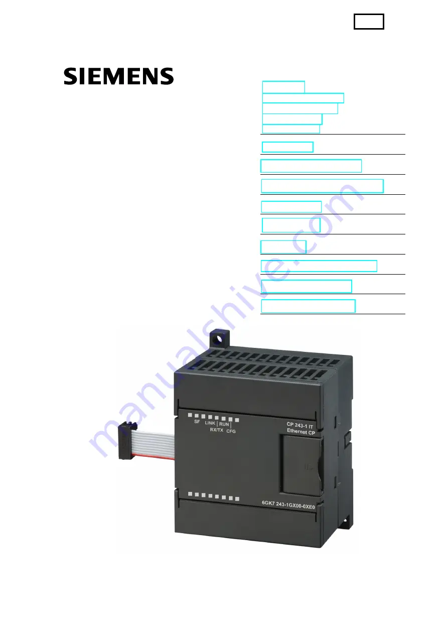
background image


SIMATIC NET 

CP 243-1 IT 
Communications Processor  

for Industrial Ethernet and 
Information Technology


Technical Manual 


Foreword 
Product Information 
Table of Contents 
List of Figures 
List of Tables 


Introduction 


Features and Functions 


Installation and Comissioning 


Configuration 


Programming 


Diagnosis 


Appendix A: Technical Data 


Appendix B: Example 


Appendix C: Timeouts 


03/2003 
J31069-D0429-U001-A0-7618 

back

Summary of Contents for CP 243-1 IT

Page 1: ... Technical Manual Foreword Product Information Table of Contents List of Figures List of Tables Introduction Features and Functions Installation and Comissioning Configuration Programming Diagnosis Appendix A Technical Data Appendix B Example Appendix C Timeouts 03 2003 J31069 D0429 U001 A0 7618 back ...

Page 2: ...tered Siemens AG Automation Drives Postfach 4848 D 90327 Nuernberg Exclusion of liability Although we have checked the contents of this publication for correspondence to the hardware and software described therein we cannot guarantee total agreement The information in this publication is reviewed at regular intervals and necessary corrections included in the next releases Your suggestions are welc...

Page 3: ...iate precautions are not taken Caution without a warning triangle means that property damage may occur if appropriate precautions are not taken Attention means that an undesired result or state may occur if appropriate precautions are not taken Note indicates important information on the product its handling or the particular part of the documentation requiring special attention Possible benefits ...

Page 4: ...rdware products Caution The device may only be used for the technical applications described in the cata log and only with products of Siemens or recommended by Siemens or devices and components of other manufacturers which have been approved by Siemens Correct safe operation of the product depends on correct transportation correct storage installation and mounting as well as careful operator cont...

Page 5: ...s of the CP 243 1 IT In addition you will need a basic knowledge of such topics as TCP IP FTP E Mail HTML Web Browser and Java Target group This manual is written for engineers programmers commissioning personnel and maintenance personnel with a general knowledge of automation and communica tion systems as well as user interface systems Sample program This manual contains a sample program which gi...

Page 6: ... label MAC address The CP 243 1 IT is delivered with a permanently set MAC address This MAC ad dress is shown on a label underneath the upper covering flap of the device MLFB number scope of delivery Product Name MLFB Scope of Delivery CP 243 1 IT 6GK7 243 1GX00 0XE0 CP documentation on CD ROM ...

Page 7: ...n 23 2 3 1 Preliminary Remarks 23 2 3 2 Types of Communication 24 2 3 3 E Mail 25 2 3 4 FTP Server 27 2 3 5 FTP Client 29 2 3 6 HTTP Server 33 2 4 File System 37 2 5 User Administration 39 2 6 Security 41 2 6 1 Configuration 41 2 6 2 Data Security 42 2 6 3 Communication Security 42 2 7 Connections 43 2 8 Indicators Front LEDs 44 3 Installation and Commissioning 47 3 1 Dimensions for Installation i...

Page 8: ...re of Configuration Data Block CDB 70 4 4 3 Structure of the Network Parameter Block NPB 74 4 4 4 Structure of the Network Data Block NDB 74 4 4 5 Structure of the Internet Data Block IDB 76 4 4 6 Structure of the Configuration File for User Administration udb File 79 4 4 7 Structure of the Configuration File for the E Mail Client edb File 82 4 4 8 Structure of the Configuration File for the FTP C...

Page 9: ...03 03 Table of Contents CP 243 1 IT J31069 D0429 U001 A0 7618 9 Appendix A Technical Data 121 Appendix B Example 123 Appendix C Timeouts 131 Abbreviations 133 ...

Page 10: ...ce requirements during installation 49 Fig 6 Dimensions for installation in a control panel 50 Fig 7 Dimensions for installation on a DIN rail 50 Fig 8 Screen Properties S7 connection 90 Fig 9 Calling the subprogram ETHx_CTRL 96 Fig 10 Call of the subprogram ETHx_CFG 98 Fig 11 Call of the subprogram ETHx_XFR 100 Fig 12 Call of the subprogram ETHx_EMAIL 102 Fig 13 Call of the subprogram ETHx_FTPC 1...

Page 11: ...IDB 78 Table 12 Structure of the configuration file for user administration 79 Table 13 Structure of the parameter record of a user 80 Table 14 Structure of the configuration file for the e mail client 83 Table 15 Structure of the configuration file for the FTP client 85 Table 16 Structure of the parameter record for an FTP job 87 Table 17 Input parameters ETHx_CTRL 96 Table 18 Return parameters E...

Page 12: ...le information 108 Table 28 Layout of the NPB memory area 109 Table 29 Error messages in byte format 115 Table 30 Error messages in word format 118 Table 31 Error messages for test routine for e mails 119 Table 32 Technical data 122 Table 33 Timeouts on Ethernet 131 Table 34 Timeouts on the backplane bus 132 ...

Page 13: ...T open communication system Physically Industrial Ethernet is an electrical network based on shielded coaxial lines twisted pair cabling and an optical network of fiber optic conductors Industrial Ethernet is defined by the in ternational standard IEEE 802 3 Continuous communication in the industrial area worldwide Industrial Ethernet is embedded in the SIMATIC NET concept which permits con tinuou...

Page 14: ...ained from a BOOTP server Programming Use the Internet wizard of STEP 7 Micro WIN 32 to program communication in the user program see chapters 4 and 5 Configuration The firmware of the CP 243 1 IT is programmed on flash memory during produc tion and is stored there permanently System states or dynamic variables which occur during operation of the CP 243 1 IT are not stored permanently Configuratio...

Page 15: ...ll TCP transport connections with active and passive partners IT communication File system for permanent storage of Web and configuration files on the CP 243 1 IT SMTP client for sending e mails In addition to pure text information em bedded variables can also be transmitted The current value of such a variable is not determined until the e mail is sent Configuration of up to 32 e mails with up to...

Page 16: ...ion of the IT functions is stored on the CP 243 1 IT this must be loaded again to the module when the CP 243 1 IT is replaced Watchdog timer The CP 243 1 IT is equipped with a watchdog circuit The watchdog starts each time the CP 243 1 IT boots The watchdog monitoring time is usually 5 seconds Tolerances due to components may increase this time to 7 seconds If watch dog monitoring triggers the CP ...

Page 17: ...has been sent does the CP 243 1 IT ac cept a new job If the CP 243 1 IT receives several jobs on a channel configured as server only the first job is processed The subsequent jobs are ignored until the end of the transaction i e until a response is sent The CP 243 1 IT has no channel specific job administration and does not buffer jobs Prerequisites for communication with a PC PG As before a PG PC...

Page 18: ...CPU must support the function S7 communication With systems from the S7 300 family an XPUT XGET client can only be used with a related communications processor starting with version 1 1 You will find the ver sion of your communications processor in the MLFB number among others If you are using a CP 343 1 the MLFB number must contain the character string EX11 or higher Always remember that the CP 2...

Page 19: ... an OPC server A maximum of 8 connections see Fig 1 are possible in addition to a STEP 7 Micro WIN connection Configuring and programming connections for S7 stations To configure communication between an S7 200 and an S7 300 S7 400 or an OPC server you will need both STEP 7 Micro WIN 32 starting with version 3 2 3 and STEP 7 starting with version 5 1 with service pack 3 or higher with NCM for Indu...

Page 20: ...can also be permanently specified by the user when configuring the CP 243 1 IT If the CP 243 1 IT doesn t have a valid configuration it always uses auto negotiation mode Note Auto negotiation mode only works when all connected network components sup port this mode Industrial Ethernet and TCP IP do not allow time deterministic data flow There is no way to know when a geographically remote CPU will ...

Page 21: ...nputs outputs markers and data areas with an S7 300 or an S7 400 as partner CP 243 1 IT a server Write accesses Data type is BOOL BYTE WORD or DWORD Use of data types CHAR INT DINT and REAL depends on the firmware status of the S7 200 CPU being used Accessible memory areas on the local system are inputs outputs variables markers and status bits Read accesses Data type is BOOL BYTE WORD or DWORD Us...

Page 22: ...P 243 1 IT J31069 D0429 U001 A0 7618 22 Backplane bus communication All accesses to all data areas of the S7 200 CPU are always possible The read and write accesses are not dependent on whether the CPU is in RUN TERM or STOP status ...

Page 23: ...b browsers to access data and status information on the S7 200 system at the same time See Fig 2 Sending an e mail or active file access via FTP are initiated by the S7 200 user program Only one job at a time can be active for each of these two functions Not until the CP 243 1 IT has positively or negatively acknowledged the job can the user program start another job Ethernet HTTP CPU 2xx CP 243 1...

Page 24: ...an be used individually or in combination 1 Communication with an e mail server 2 Communication with an FTP client located in a geographically remote system 3 Communication with an FTP server Such a server is usually located in a geo graphically remote system However a coupling to the FTP server running on the CP 243 1 IT of the local S7 200 system is also possible 4 Communication with up to four ...

Page 25: ...figuration by an IP address and a port num ber must be located in the subnetwork of the CP 243 1 IT or be able to be ac cessed via a gateway If this e mail server cannot be accessed the e mail is sent to a substitute e mail server which is also specified when the CP 243 1 IT is con figured If this substitute e mail server is also not accessible an appropriate error message is generated Caution The...

Page 26: ...onfigured Each e mail text may consist of up to 1024 characters The structure of each e mail is shown below E mail number This number can be used to reference a configured e mail by the S7 200 user program Receiver address The e mail address of the receiver This address must always be specified Additional receiver address The address of a recipient who is to receive a copy of the e mail This ad dr...

Page 27: ...ance general conditions Sending of e mails is subordinate to S7 communication Reaction times when sending an e mail depend on the configuration and cannot be specified in general The greater the number of simultaneous S7 connections and the larger the amount of data to be transmitted over these connections the longer it takes to process and send e mails Caution The placeholders embedded in the e m...

Page 28: ... up to 8 users with special rights and the location at which the fixed user name and the related password are stored The user names and passwords are configured with STEP 7 Micro WIN 32 The configuration file created by the Internet wizard to be used here is transferred with FTP to the CP 243 1 IT and stored permanently in the file system there in a file with the ending udb The user name and the p...

Page 29: ...FTP communication depend on the particular configuration and cannot be generally specified in advance Note Only one FTP client may access the FTP server at a time When the FTP server of the CP 243 1 IT is accessed by the S7 user program via the FTP client function a geographically remote FTP client cannot be accessed The reverse also applies 2 3 5 FTP Client How it works The FTP client of the CP 2...

Page 30: ... conversion or formatting of these data The data to be transferred are not stored permanently on the CP 243 1 IT Configuration The FTP jobs are configured with the Internet wizard of STEP 7 Micro WIN 32 The configuration data entered here are permanently stored in the file system of the CP 243 1 IT in a file with the ending fdb Transmission of these data from the system on which the configuration ...

Page 31: ...ated deactivated with the configuration Communication partners All FTP clients which communicate via Ethernet and which comply with RFC959 standards are always considered possible communication partners of the FTP cli ent This means communication is not only possible with PC based FTP servers but also with FTP servers running on S7 200 S7 300 or S7 400 systems for in stance Performance general con...

Page 32: ...e is output by the S7 200 user program The transaction is not repeated automatically On the CP 243 1 IT data communication via FTP is subordinate to S7 communica tion Reaction times vary with the particular configuration as well as the length of the S7 200 application program and generally cannot be predicted in advance Note The file DB routine of communications processors CP 343 1 IT and CP 443 1...

Page 33: ...d transfer them to the file system of the CP 243 1 IT with the help of an external FTP client Java Beans are provided on the documentation CD of the CP 243 1 IT for simple creation of Java Applets They can be copied from there to a development com puter and then with the aid of a Java development environment e g Visual Age from IBM linked to your own Java Applets The Beans included with the CP 243...

Page 34: ...CP 243 1 IT is then granted or re fused depending on the access rights assigned to the user by user administration The HTTP server of the CP 243 1 IT can always be activated deactivated with the configuration HTML pages on the CP 243 1 IT The file system of the CP 243 1 IT contains already prepared HTML pages in Eng lish which already supply status and diagnostic information via integration of the...

Page 35: ...O CC and the fields of the subject and the text are limited to a maximum of 64 characters each When the page is called the user is asked to authenti cate himself with a user name and a password Only the administrator is authorized to send a test e mail The errors which can occur are described in chapter 6 3 http destination IP address __S7Sys it_info Present status of the CP 243 1 IT This page ind...

Page 36: ...ink in Java Applets To ensure that this functions correctly the execution of Java Applets must be enabled on the Web browser Communication partners All HTTP clients e g Web browsers represent potential communication partners of the HTTP server The HTTP server of the CP 243 1 IT supports simultaneous access of up to 4 Web browsers The TCP IP connection to the HTTP server is always handled by port 8...

Page 37: ...d The file system supports path and file names up to a total length of 254 characters The drive name of the flash file system flash is also added to the 254 charac ters This means that after the drive name is deducted 247 characters remain for a maximum path including the file name The actual file name and every name of a directory can have a maximum length of 99 characters The maximum nesting dep...

Page 38: ...s files from the directories __S7Sys and examples When storing user files appropriate subdirectories should always be set up to store these files under flash applets This directory contains several jar files which are required for S7 Applets These jar files contain the Java Beans included with the CP 243 1 IT on the documentation CD in compressed format This directory should not be deleted flash c...

Page 39: ...T does not support user groups Administrator In addition to these 8 users the user administration of the CP 243 1 IT recognizes another user with special access rights the administrator The administrator is the only user who may access the directory __S7Sys and store the udb configuration file for user administration via FTP in the file system of the CP 243 1 IT The user name and the password of t...

Page 40: ...rd protection Pass word protection is not activated until process values of the S7200 system are ac cessed by such pages Note We recommend not allowing the 8 configurable users access to the FTP If a user is permitted access to the FTP this user has the opportunity to change the configu ration data stored in the file system of the CP 243 1 IT Note To keep configuration effort as low as possible wi...

Page 41: ...desired changes in the stored configuration data This CRC routine can also be deactivated however The configuration can then be changed manually or by an S7 200 user program Caution Since after the CRC check is disabled the CP 243 1 IT is no longer able to check the configuration data for consistency concerning desired or undesired changes there is no guarantee whatsoever that the CP or the compon...

Page 42: ...owever program variables or I O values are not updated Caution The user name and related password required to log in on an FTP server are al ways transmitted unencrypted over the network in accordance with valid general specifications of the FTP protocol 2 6 3 Communication Security The CP 243 1 IT is equipped with a Keep Alive routine This means that the CP 243 1 IT is able to automatically recog...

Page 43: ... 243 1 IT is equipped with the following connections Terminal block for 24 V DC power and grounding connection 8 pin RJ45 socket for Ethernet connection Pin plug connector for backplane bus Integrated ribbon cable with connection socket for the backplane bus The connections are located under the covers of the front flaps ...

Page 44: ...ver could be found LINK Green continu ously on Connection via the RJ45 interface Ethernet connection is established RX TX Green flickering Ethernet activity Data are received or sent via Ethernet Note A packet received via Ethernet must not always be intended for the CP 243 1 IT The CP 243 1 IT first accepts all packets transmitted via Ethernet and then decides whether the packet is intended for i...

Page 45: ... continu ously on Configuration Is on when STEP 7 Micro WIN 32 actively maintains a connection to the S7 200 CPU via the CP 243 1 IT Table 4 Function of the individual LEDs During the startup phase of the CP 243 1 IT the SF LED flashes twice The LINK and the RX TX LEDs then flash several times As soon as the RUN LED goes on the CP 243 1 IT startup is concluded ...

Page 46: ...Installation and Commissioning 03 03 CP 243 1 IT J31069 D0429 U001 A0 7618 46 ...

Page 47: ...The position in an S7 200 system in which a CP 243 1 IT can be operated de pends on the firmware version of the S7 200 CPU you are using With a firmware version greater than or equal to 1 2 the CP 243 1 IT can be used in any position in an S7 200 system With a firmware version less than 1 2 the CP 243 1 IT must be installed directly next to the S7 200 CPU Wiring Warning If you attempt to install o...

Page 48: ...unded conductor together with a phase conductor or a signal line Separate alternating current wiring and high voltage direct current wiring with fast switching sequences from the low voltage signal wiring Provide suitable overvoltage protection for lines which may be hit by lightning The S7 200 CPU and the CP 243 1 IT should be connected to the same power supply The CP 243 1 IT is equipped with an...

Page 49: ...stalled horizontally the CP 243 1 IT must always be installed to the right next to the CPU When installed vertically the maximum permissible ambient temperature drops by 10 C The CP 243 1 IT must be positioned above the CPU If you are using a vertical standard DIN rail you should use standard DIN rail stoppers to pre vent the module from slipping Installation depth is 75 mm Note Set up your device...

Page 50: ...2 mm 71 2 mm 96 mm 88 mm 80 mm Minimum distance of 9 5 mm between the modules when installed in the switching cabinet wirh M4 screws CPU Fig 6 Dimensions for installation in a control panel 3 2 Dimensions for Installation on a DIN Rail The CP 243 1 IT can be mounted on a DIN rail DIN EN 50 022 The following figure shows the dimensions of a standard DIN rail 35 mm 7 5 mm 1 0 mm Fig 7 Dimensions for...

Page 51: ...s with a cross section of 1 5 mm 2 for this 5 Connect the power supply 6 Connect the Ethernet cable The transmission medium is a 2 x 2 core twisted pair shielded line with a ripple resistance of 100 Ohm The transmission properties of this line must meet cate gory 5 requirements Cat5Cable The maximum length of the connection be tween terminal and network components link segment is limited to 100 m ...

Page 52: ... recommend connecting all grounding terminals individually Use lines with a cross section of 1 5 mm 2 for this 5 Connect the power supply 6 Connect the Ethernet cable The transmission medium is a 2 x 2 core twisted pair shielded line with a ripple resistance of 100 Ohm The transmission properties of this line must meet cate gory 5 requirements Cat5Cable The maximum length of the connection be twee...

Page 53: ... module is replaced no new pro gramming is required on the S7 communication side since configuration data and the user program are stored retentively on the S7 200 CPU The CP 243 1 IT must be programmed again for the IT functions since the configuration files among oth ers for the IT services are stored in the file system of the CP 243 1 IT ...

Page 54: ...urned off before you begin wiring Proceed as shown below to remove the CP 243 1 IT another expansion module of the S7 200 1 Turn off the power supply of the S7 200 CPU the CP 243 1 IT and all expan sion modules 2 Disconnect all cables and lines from the device which you want to remove 3 Open the front covering flap and disconnect the ribbon cable from the adjacent modules 4 Disconnect the screws o...

Page 55: ...ble when the CRC routine is disabled Since after being disabled the CRC routine of the CP 243 1 IT can no longer completely check these configuration data for consistency of intended or unin tended changes there is no guarantee whatsoever that the CP or the components connected in the network will function correctly for this application Caution To ensure that the configuration data of the CP 243 1...

Page 56: ...rvices can be loaded to the CP 243 1 IT If an S7 200 system is to communicate via a CP 243 1 IT with an S7 300 an S7 400 or an OPC based system use an S7 300 S7 400 or OPC based STEP 7 sys tem with at least version 5 1 with service pack 3 or higher with NCM S7 for Indus trial Ethernet for configuration Note After startup the CP 243 1 IT may automatically change the configured gateway due to specia...

Page 57: ...n be used during configuration of the FTP client service This causes data to be transferred between the memory of the local S7 200 CPU and the file system of the local CP 243 1 IT when the appropriate func tion is called 4 2 2 Subnet Mask If a subnet mask is specified in the configuration its layout must comply with the general conventions governing the validity of subnet masks Remember that the v...

Page 58: ...CII characters In addition to the two control characters n and t the text may contain placeholders defining an embedded data value When sending an e mail the CP 243 1 IT reads the current value of such a placeholder from the local S7 200 CPU formats it and inserts it in the message Such placeholders use the following syntax address positions_before_decimal positions_after_decimalFormat The percent...

Page 59: ...al point If a data value to the right of the decimal point contains zeros these are represented as defined by the element positions_after_decimal If the element positions_after_decimal is zero the value is indicated without decimal point The valid range for the element positions_after_decimal is between 01 and 10 The format element specifies the format for indicating the embedded value The format ...

Page 60: ...our CP 243 1 IT You can enter all relevant configuration data in several screens User prompting is designed so that you cannot switch to the next screen until all your entries are correct and complete If not an error message appears The Internet wizard consists of four internal wizards which are used to configure the various IT services First open the configuration wizard In this wizard basic conf...

Page 61: ... are two ways to enter the TCP IP address parameters 1 Enter these parameters manually in the applicable input boxes 2 Activate the access to a BOOTP server In this case the CP 243 1 IT obtains the TCP IP address parameters from a BOOTP server during startup If the CP 243 1 IT is unable to find a BOOTP server in its TCP IP network it performs a reset restarts and tries again to establish contact w...

Page 62: ...and the specified communication partner must also be specified in an extra screen This is where you specify whether these data are to be read or written Up to 32 read write jobs can be specified per connection If your S7 200 system is to be a server for a connection you can assign an IP ad dress to specify which communication partner will have access to your system You can also set each server so ...

Page 63: ... user program has made undesired changes to the configuration data If the CRC routine is not activated your user program can change the configuration data of the CP 243 1 IT However the CP 243 1 IT does not notice when this data is accidentally overwritten Caution An S7 200 user program can only change the configuration data on the S7 200 CPU when the CRC routine is off Since after the CRC routine...

Page 64: ...nt in the configuration activation or non activation of an IT service has no effect on the configuration steps below Specifying the area in which to store the configuration In the next screen specify the memory area in which your configuration data are to be stored on the S7 200 CPU The wizard will prompt you through Information on the subprograms In the next screen the wizard tells you which subp...

Page 65: ...is loaded to the S7 200 system Configuring the e mail address and the e mail server to be used In the first screen of the e mail wizard assign an e mail address to your S7 200 system The e mail address specified here will be entered as the sender address in all transmitted e mails Then choose an e mail server to which your CP 243 1 IT is to transmit the e mails to be sent Enter the IP address and ...

Page 66: ...o be sent from your S7 200 user program via the FTP client on the CP 243 1 IT The FTP server does not need to be configured This server is automatically started by the CP 243 1 IT during startup Access rights to this FTP server are specified in the configuration of the user administration Configuring the FTP jobs To configure an FTP job you must first specify whether this is a read write or de let...

Page 67: ...1 IT Some of the configuration data of the CP 243 1 IT are stored in the memory of the S7 200 CPU while some are stored in the file system of the CP 243 1 IT The memory of the S7 200 CPU contains the Ethernet configuration and the basic settings e g activation or deactivation of individual IT services made for an IT configuration While it is booting the CP 243 1 IT reads this part of the configura...

Page 68: ...U for consistency in relation to desired and undesired changes there is no guarantee whatsoever for this appli cation that the CP or the components connected on the network will function cor rectly Note Data of type WORD 2 bytes or DWORD 4 bytes are stored on an S7 200 in big endian format Address n MSB Address n 1 LSB for DWORD accordingly Alternate configuration of the IT functions STEP 7 Micro ...

Page 69: ...ided into the following data blocks Configuration Data Block CDB Network Parameter Block NPB Network Data Block NDB Internet Data Block IDB The following table shows the relationship between the position of a module in the S7 200 system and the related system marker area Position in S7 200 System Occupied Marker Area Remarks CPU 0 200 to 249 1 250 to 299 Only supported for CPU firmware versions st...

Page 70: ...rved for STEP 7 Micro WIN 32 2 bytes hex 13 14 Common flag Bit 0 Duplex mode 0 Half duplex 1 Full Duplex Bit 1 Data rate 0 10 Mbit sec 1 100 Mbit sec Bit 2 Auto negotiation 0 No auto negotiation 1 Auto negotiation Bit 3 BOOTP 0 Use configured network pa rameters 1 BOOTP Bit 4 7 Not used Bit 8 15 CRC validation 16 00 CRC check activated 16 AC CRC check deactivated 2 bytes hex 16 0004 Auto negotiati...

Page 71: ...lid 0 Section not used 1 Section used 1 byte hex 16 82 Server Keep Alive support S7 connection 0 is being used and contains valid data 30 33 With server functionality IP address area of client for access protection 16 00000000 No protection 16 XXXXXX00 Client of same class C segment is permitted 16 XXXXXXXX Only exactly the same address is permitted With client functionality IP address of the S7 s...

Page 72: ...x See S7 connection 0 section S7 connection 4 section If not all bytes of this section are used fill them with16 00 65 Flag byte See S7 connection 0 section 1 byte hex See S7 connection 0 section 66 69 IP address of the partner See S7 connection 0 section 4 bytes hex See S7 connection 0 section 70 71 Local TSAP 2 bytes hex 16 1400 72 73 Remote TSAP 2 bytes hex See S7 connection 0 section S7 connec...

Page 73: ...n 0 section 4 bytes hex See S7 connection 0 section 97 98 Local TSAP 2 bytes hex 16 1700 99 100 Remote TSAP 2 bytes hex See S7 connection 0 section STEP 7 Micro Win server section 101 Flag byte Bit 0 Server 0 Server 1 Not supported Bit 1 Keep Alive 0 No Keep Alive support 1 Keep Alive support Bit 2 6 Not used Bit 7 Section valid 0 Not supported 1 Section used 1 byte hex 16 82 Server Keep Alive sup...

Page 74: ...Varies with the cur rent configuration 2 bytes hex 16 04 Auto nego tiation Use configured network parame ters 110 113 Current IP address Varies with the cur rent configuration 4 bytes hex 192 12 45 23 16 C00C2D17 114 117 Current subnet mask Varies with the cur rent configuration 4 bytes hex 255 255 255 0 16 FFFFFF00 118 121 IP address of the current gateway Varies with the cur rent configuration 4...

Page 75: ...e hex n bytes n 132 COM_CH0_LENn Specifies the length of the COMn structure 1 byte hex n 5 COM_CH0_0 COM0 structure for read write job 0 for first client channel op cnt local_buffer remote_buffer For a description see Table 10 ASCII ASCII 1 0 _ 0 _ 5 n i LENi CH COM n COM_CH0_n COMn structure for read write job n for first client channel op cnt local_buffer remote_buffer For a description see Tabl...

Page 76: ...e range IB0 to IBx whereby x is the max input address S7 200 S7 300 S7 400 QB0 to QB whereby x is the max output address S7 200 S7 300 S7 400 MB0 to MBx whereby x is the max marker address S7 200 S7 300 S7 400 VB0 to VBx whereby x is the max variable address S7 200 DB0 DBB0 to DBx DBBy whereby x is the max DB number and y is the highest address in the data block within the DB S7 300 S7 400 ASCII T...

Page 77: ...eb Bit 1 7 Reserved 1 byte hex 16 01 Admin is enabled for all IT functions 9 24 CP 243 1 IT admin user name User name min of 1 max of 16 characters long Unused bytes are filled with 16 00 16 ASCII characters bytes admin 16 61 a Byte 0 16 64 d Byte 1 16 6d m Byte 2 16 69 i Byte 3 16 6e n Byte 4 16 00 0 Bytes 5 15 25 56 CP 243 1 IT admin password The password is encrypted and stored with a character...

Page 78: ... Enable bit 0 Disabled 1 Enabled Bit 1 15 Reserved 2 bytes hex 16 0001 FTP client enabled FTP server section 61 62 FTP server flag Bit 0 15 Reserved 2 bytes hex 16 0000 HTTP client section 63 64 HTTP server flag Bit 0 Enable bit 0 Disabled 1 Enabled Bit 1 15 Reserved 2 bytes hex 16 0001 HTTP client enabled CRC section 65 66 CRC 2 bytes hex Table 11 Structure of the IDB ...

Page 79: ... monitors this element for change When a change is determined the udb file is com pletely read and the user admini stration of the CP 243 1 IT is recon figured TIMESTAMP 3D2C4E48 Corresponds to 15 10 00 o clock on 07 10 2002 FILETYPE File type Used internally by the system FILETYPE UDB Don t change Fixed value FILEFORMAT File format Used internally by the system FILEFORMAT xx Don t change Fixed va...

Page 80: ...31 Not used 00 00010048 User name Password Read and write access via HTTP Access to status page of the CP 243 1 IT via HTTP server Access to all FTP functions User name The user name is presented in plain text and consists of 1 to 32 characters 00 00000040 Status_CP Password The user with the user name Status_CP is authorized to read the status of the CP 243 1 IT Password The password is encrypted...

Page 81: ...added to the file with the character A blank user entry is rejected in the udb file as follows 0x 00000000 whereby x stands for the running user number The last character of a line is a n All ASCII characters between 0x21HEX and 0x7E HEX can be used for the user name and password if they are acceptable to the communication partners involved Blank lines are not permitted Caution When you change the...

Page 82: ... t change Fixed value FILEFORMAT File format Used internally by the system FILEFORMAT xx Don t change Fixed value FROM Sender address of the station sending the e mail FROM Anlage Werk2 Firma com SMTPSA1 IP address of the e mail server SMTPSA1 192 168 1 10 SMTPSP1 Port address of the e mail server SMTPSP1 25 SMTPSA2 IP address of the substitute e mail server SMTPSA2 192 168 162 97 SMTPSP2 Port add...

Page 83: ...entifier Table 14 Structure of the configuration file for the e mail client Example of an e mail configuration file This is a comment TIMESTAMP 3D2C4E48 FILETYPE EDB FILEFORMAT 01 FROM Anlage Werk2 Firma com SMTPSA1 192 168 1 10 SMTPSP1 25 SMTPSA2 192 168 162 97 SMTPSP2 25 00 TO Name Name provider de 00 CC Name Name provider de 00 SU Status Station 4 00 TX Störung im Anlagenabschnitt 10 01 TO Name...

Page 84: ...y not contain more than 64 ASCII characters The subject SU may not contain more than 128 ASCII characters The e mail text TX may not contain more than 1024 ASCII characters incl e mail tags and formatting characters The sender address FROM may not contain more than 64 ASCII characters All characters between 0x21HEX and 0x7E HEX can be used for TO CC SU and TX if this is acceptable to the e mail pa...

Page 85: ...e system FILEFORMAT xx Don t change Fixed value FTP job 00 identification of the 32 possible FTP jobs with 00 01 30 31 00 Parameter record of FTP job 00 Action number of bytes DB start address path file name server ad dress user name password all separated by a 00 Action Number of bytes DB start address Path file name Server ad dress User name Password For a description see Table 16 FTP job 01 ide...

Page 86: ... and Password written to the file Path file name on the computer specified by Server address DB start address Start address starting at which the DB block can be read or written The value range refers to the size of the actual DB block varies with the CPU with CPU226XM between 0 and 10239 00 R 5354 VB2308 Path file name Server address User name Password The file Path file name is transferred from ...

Page 87: ...The file flash dat CPU10_VB11_23 dat is transferred from the file system of the FTP server which can be accessed via IP address 192 168 162 65 stating user name FTP_Server4 and Password to the CP 243 1 IT There 23 bytes from the file are written to the DB of the CPU starting at address VB11 Password The password belonging to the specified user name Is encrypted and stored with a char acter length ...

Page 88: ...is n All characters between 0x21HEX and 0x7E HEX can be used for path file name user name and password if this is acceptable to the communication partners involved The following additional restrictions apply to directory and file names Not supported blanks and Blank lines are not permitted Caution With a READ action Number of bytes is usually between 0 and 10240 maxi mum with the CPU 226XM When th...

Page 89: ...mmuni cate with an S7 200 system via the related Ethernet communications processor The procedure is similar for S7 400 systems For detailed information on the configuration steps see the STEP 7 description or the manuals of the CP 343 1 and CP 443 1 With S7 300 and S7 400 systems a distinction is made between configured and free connections With configured connections the connection parameters are...

Page 90: ... S7 connection see Fig 8 specify whether your S7 300 or S7 400 system is to be the active or passive station If your S7 300 or S7 400 system is to communicate with an S7 200 system you must also specify whether your system is the client or the server If you want your S7 300 or S7 400 to be the client activate the entry activ connection generation If this entry is not activated your system will be ...

Page 91: ... and enter the TSAP specified in STEP 7 in the entry Local as the connection access point for your S7 300 system Instead you must first re shape this TSAP according to the following rules 1st byte of the TSAP Is taken from STEP 7 screen Adress details entry Local field TSAP 2nd byte of the TSAP Is derived from the rack and the slot of your Ethernet communications processor on your S7 300 system Th...

Page 92: ... via connections which were configured on the S7 300 or S7 400 system Just remember that with free connections the first byte of the TSAP with which such connections run on S7 300 and S7 400 systems must always have the value 0x03 The second byte of the TSAP is derived similar to the above described procedure from the rack and the slot number of the CPU used on your S7 300 or S7 400 system This me...

Page 93: ...ly able to access the S7 200 CPU via Ethernet from STEP 7 Micro WIN 32 A new valid configuration can now be ob tained in this way Communication with other controllers is not possible in this state After a reset the CP 243 1 IT then accepts the settings of the new configura tion Note Auto Negotiation mode will only work when all connected network components support this mode Note If no valid CDB ND...

Page 94: ...Programming 03 03 CP 243 1 IT J31069 D0429 U001 A0 7618 94 ...

Page 95: ...rresponds to the slot position possible values 0 1 6 ETHx_FTPC x corresponds to the slot position possible values 0 1 6 At the end of configuration these subprograms are generated by the Internet wiz ard integrated in STEP 7 Micro WIN 32 You will find these subprograms in STEP 7 Micro WIN 32 in the box with the operations tree under the entry Subroutine The data which you entered during configurat...

Page 96: ...al state of the CP 243 1 IT the state of up to eight possible S7 communication channels and the state of the IT services When an error occurs on the CP 243 1 IT you can read out the error or message code with the Error return parameter This code is available for a maximum of 60 seconds The CP 243 1 IT assumes that during this time the S7 200 user pro gram has evaluated the error or message code an...

Page 97: ...rresponds to channel 4 Bit 13 corresponds to channel 5 Bit 14 corresponds to channel 6 Bit 15 corresponds to channel 7 0 Channel or service not ready 1 Channel or service ready Error WORD Error or message code 0x0000 No error Other Error for a description see chapter 6 2 The error or message code is only available for a maximum of 60 seconds Table 18 Return parameters ETHx_CTRL The value 1 in a bi...

Page 98: ...s running This program is only created by the Internet wizard on STEP 7 Micro WIN 32 when the CRC rou tine is not activated there for your configuration When the subprogram ETHx_CFG is called the CP 243 1 IT terminates all existing connections and performs a reset As soon as the CRC routine is activated however you can no longer change the configuration from a user program This is then only possib...

Page 99: ...cessed Whether these data are to be read or written The communication partner from which these data are obtained or to which these data are transferred When you call the subprogram ETHx_XFR you specify which of the configured cli ent channels you want to use for which configured data accesses The subprogram ETHx_XFR is only created by the Internet wizard in STEP 7 Mi cro WIN 32 if you have configu...

Page 100: ...d write job 0 Don t trigger read write job 1 Trigger read write job Chan_ID BYTE Number of the channel via which the data is to be accessed This channel must be configured as client Value range 0 to 7 Data BYTE Number of the channel specific data block from the configuration which describes the read write job to be executed Value range 0 to 31 Abort BOOL Input condition for canceling a data access...

Page 101: ... mail server to be used are specified in the configuration of the CP 243 1 IT A total of up to 32 different e mails can be configured The following is specified already during configuration Which e mail server is to be used Which data from the S7 200 system in addition to the actual e mail text will be embedded in the e mail Who will receive the e mail When you call the subprogram ETHx_EMAIL you s...

Page 102: ... the e mail from the configuration which describes the e mail job to be executed Value range 0 to 31 Abort BOOL Input conditions for canceling an e mail job 0 Don t cancel e mail job 1 Cancel e mail job Table 23 Input parameters ETHx_EMAIL Return parameters Name Type Meaning Done BOOL Status of the subprogram call 0 Subprogram not executed yet 1 Subprogram executed e mail job con cluded subprogram...

Page 103: ...er you want data to be read from your S7 200 CPU and transferred to an FTP server Whether you want to request a file from an FTP server and copy it to your S7 200 CPU Whether you want to delete a file from the file system of an FTP server Which data lengths start addresses file names FTP server addresses user names and passwords you want to use for the action When the subprogram ETHx_FTPC is calle...

Page 104: ...START BOOL Input condition for triggering a read write delete job 0 Don t trigger read write delete job 1 Trigger read write delete job Op BYTE FTP client job number from the configuration which describes the read write delete job to be executed Value range 0 to 31 Abort BOOL Input condition for termination of an FTP client job 0 Don t cancel FTP client job 1 Cancel FTP client job Table 25 Input p...

Page 105: ...d yet 1 Subprogram executed read write delete job concluded subprogram ready for next job Error BYTE Error code 16 00 No error Other Error for a description see chapter 6 2 Table 26 Return parameters ETHx_FTPC Caution FTP client communication is subordinate to S7 communication Reaction times vary with the configuration and cannot be predicted in general terms ...

Page 106: ...Diagnosis 03 03 CP 243 1 IT J31069 D0429 U001 A0 7618 106 ...

Page 107: ...ation module type and version states used TCP IP address parameters IP address subnet mask IP address of the gateway and the MAC address When a configuration error occurs and booting is performed later with the BOOTP routine the values shown here are not valid This same applies when the user program has not completed at least one cycle Status messages Information on the embedding of the CP 243 1 I...

Page 108: ...1 0 BOOTP sequence not performed 1 BOOTP sequence performed Bit 2 0 CP 243 1 IT not ready 1 CP 243 1 IT ready Bit 3 0 STEP 7 Micro Win 32 not active 1 STEP 7 Micro Win 32 active Bit 4 0 Configuration in acc w CDB 1 No valid configuration in CDB Bit 5 Reserved Bit 6 0 No Ethernet connection 1 CP 243 1 IT connected with Ethernet Bit 7 0 No error on CP 243 1 IT 1 CP 243 1 IT in error state 1 byte hex...

Page 109: ...uplex 1 Full duplex Bit 1 Data rate 0 10 Mbit sec 1 100 Mbit sec Bit 2 Auto negotiation 0 Auto negotiation not active 1 Auto negotiation active Bit 3 BOOTP 0 Network parameters from configuration 1 Network parameters from BOOTP Bit 4 Bit 15 Reserved 2 bytes hex 110 113 Current IP address 4 bytes hex 114 117 Current subnet mask 4 bytes hex 118 121 IP address of the currently used gateway 4 bytes he...

Page 110: ...he contents of the file system on the CP 243 1 IT should be checked from an FTP client If necessary faulty files can sometimes be corrected with this method Note The abrupt conclusion of a CP 243 1 IT with active client connections e g due to a power failure while the server continues running may result in the server s not recognizing that the connections have been interrupted When the client then...

Page 111: ...g on the type of error the following bytes are used for the error message in the current SM area of your CP 243 1 IT Global errors and general messages are transferred at byte offset 20 and 21 They are interpreted as a word SMW The error or message codes transmitted here are deleted again after a maximum of 60 seconds This rou tine prevents outdated error or message codes from blocking these two b...

Page 112: ...eturns errors indicating a problem with the configuration check to determine whether your user program may have overwritten the configu ration Caution During power failures 24 V the CP 243 1 IT is unable to return any more error messages 6 2 1 Error Messages in Byte Format Error Byte Transfer Rou tine Hex Dec Description Reaction Correction Byte Offset in SM Area Return Value ETHx_ 16 01 1 Time ex...

Page 113: ...e communication partner Check fdb file on the CP 243 1 IT for uniqueness and com pleteness 35 _FTPC The FTP connection was termi nated Check connection path to the communication partner Check FTP server configuration for completeness 36 16 05 5 The connection could not be estab lished or was terminated Or an at tempt was made to execute a job and the HTTP server was not cor rectly parameterized Ch...

Page 114: ...il servers not possible Check connection path to the configured e mail servers Check configuration particu larly the edb file 34 _EMAIL 16 11 17 The registration was rejected by the e mail server Check to determine whether the e mail server is configured cor rectly Check configuration particu larly the edb file 34 _EMAIL 16 12 18 An error occurred while generating the e mail to be sent Check confi...

Page 115: ...ta transmission via FTP Check to determine whether the FTP server is configured cor rectly Check to determine whether network problems exist Check configuration particu larly the fdb file 35 _FTPC 16 80 128 External 24 V is not present Apply voltage or wait till ready 25 37 _XFR _CFG _EMAIL _FTPC 16 81 129 This channel is not ready or is faulty Wait till ready Evaluate the return parameters of the...

Page 116: ...uration of the CP 243 1 IT with STEP 7 Mi cro WIN 32 Check the user program to see whether configuration data were accidentally over written 20 21 _CTRL 16 0033 51 The configuration data for the CP 243 1 IT contain errors or are not stored correctly New configuration of the CP 243 1 IT with STEP 7 Mi cro WIN 32 20 21 _CTRL 16 0034 52 The pointer to the CDB is wrong or no CDB is loaded Make sure th...

Page 117: ... jobs or lengths Check the configuration 20 21 _CTRL 16 0093 147 The BOOTP job failed Automatic restart 20 21 _CTRL 16 0094 148 The reply of the BOOTP server contains invalid data Automatic restart 20 21 _CTRL 16 0095 149 The TCP IP stack did not ac cept the specified monitoring time Keep Alive Automatic restart 20 21 _CTRL 16 0096 150 The TCP IP stack did not ac cept the IP address specified for ...

Page 118: ...s from the file sys tem 20 21 _CTRL 16 00BF 191 System files could not be set up in the file system Delete files from the file sys tem 20 21 _CTRL 16 00F0 240 The S7 200 CPU failed to rec ognize the CP 243 1 IT Check configuration and setup of the S7 200 system _CTRL 16 00F1 241 The address of the output byte via which the CP 243 1 IT is supposed to be accessible ac cording to the configuration is...

Page 119: ...r Error during transmission via SMTP 10 FROM command failed FROM CP s own e mail address not correctly configured or unknown to e mail server 11 TO command failed TO addressee not specified correctly or un known to e mail server 12 CC command failed CC addressee not specified correctly or un known to e mail server 13 General protocol error Error during transmission via SMTP 14 Sending E Mail faile...

Page 120: ...Technical Data 03 03 CP 243 1 IT J31069 D0429 U001 A0 7618 120 ...

Page 121: ...GET or READ WRITE 1 connection to STEP 7 Micro WIN 32 Max number of IT connections One connection each for the FTP server the FTP client and the e mail client plus 4 HTTP connections Permissible ambient conditions Operating temperature Transport storage temperature Relative humidity max Operating altitude 0 o C to 55 o C with horizontal installation 0 o C to 45 o C with vertical installation 40 o ...

Page 122: ...em Max path length incl file and drive names 254 characters Max length of a file name 99 characters Max nesting depth of the directory 49 Server ports used HTTP 80 FTP command channel 21 FTP data channels for FTP server 3100 3199 S7 connection establishment 102 S7 server 3000 3008 Table 32 Technical data ...

Page 123: ...wo S7 200 stations via Industrial Ethernet A character string CP243 that is stored at address VB500 and higher and that has a length of 5 bytes is sent from the local S7 200 system to another S7 200 system stored there at the same address and then read back from there This pro cedure is repeated continuously The associated server must be configured as a corresponding counterpart The user program t...

Page 124: ...bol Address Comment ch0_ready M8 0 Bit for channel 0 in the return value CH_READY of the subroutine ETH0_CTRL start M4 0 Flip flop for automatic start of the data transmission NETWORK 3 For an S7 200 the First_Scan_ON bit is anly set in the first cycle for systemre lated reasons Thus the start variable is reset This procedure is required so that the start variable always generates a switching edge...

Page 125: ...nitiated can be aborted using the Abort parameter To do so the M7 0 flag must be set In this example this flag also acts on the read command from Network 5 After flag M7 0 is cleared read write commands are again issued since the Done bit is always set along with the Error bit after a command is aborted Applying special flag SM0 0 ensures that the ETH0_XFR subroutine is always en abled As soon as ...

Page 126: ... firstly the preceding write command is finished and secondly that the status of channel 0 is ready LD Always_On L60 0 LD ch0_done_write EU U ch0_ready L63 7 LD L60 0 CALL ETH0_XFR L63 7 Connection0_0 Read_1 Connec tion_abort ch0_done_read ch0_error_read Symbol Address Comment Always_On SM0 0 Always ON ch0_done_read M5 0 Done bit of the read command ch0_done_write M5 1 Done bit of the write comman...

Page 127: ...for module 255 255 255 0 VD23 16 C1012801 Gateway Address 193 1 40 1 VW27 30 Keep Alive Interval in seconds Connection 0 VB29 16 83 Client Connection Keep Alive Enabled VD30 16 C1012812 Address of Server for this connection 193 1 40 18 VW34 16 1000 Local TSAP for this connection 10 00 VW36 16 1000 Remote TSAP for this connection 10 00 Connection 1 VB38 16 00 Connection not defined VD39 16 00000000...

Page 128: ...00 VB124 16 00 VB125 16 00 VB126 16 00 VB127 16 00 Network Data Block Section VW128 16 0026 VB130 16 00 VB131 16 03 VB132 16 0F VB133 16 0F VB134 W 5 VB500 VB500 Message 0 for Connection 0 VB149 R 5 VB500 VB500 Message 1 for Connection 0 VW164 16 D0C3 Internet Data Block Section VW166 16 0043 VB168 16 32 VB169 16 02 VB170 16 02 VB171 16 02 VB172 16 02 VB173 16 81 VB174 16 00 Administrator Web acce...

Page 129: ...03 03 Example CP 243 1 IT J31069 D0429 U001 A0 7618 129 VW229 16 0000 HTTP Server enable flag VW231 16 9E28 Symbol Initializations VB233 0 VB234 0 VB235 1 VB500 CP243 Module ID for testing ...

Page 130: ...Example 03 03 CP 243 1 IT J31069 D0429 U001 A0 7618 130 ...

Page 131: ...Time before arriving requests for con nection are processed Delay of the next connection estab lishment 1 Wait time after an unsuccessful attempt by a client to establish a connection Attempt to establish a connection is repeated 10 Wait time of a client for confirmation of a request to establish a connection Client disconnects the connection and connects itself again 6 Maximum time for successful...

Page 132: ...the booting S7 CPU must have detected the CP 243 1 IT physically CP 243 1 IT performs a restart 1 Maximum time until the configured e mail server must have accepted a request for the establishment of a connection Connection is not established The CP 243 1 IT reports an error 20 Maximum time until the configured FTP server must have accepted a request for the establishment of a connection Connectio...

Page 133: ...rotocol HW Hardware ICMP Internet Control Message Protocol ID Identifier IDB Internet Data Block IE Industrial Ethernet IP Internet Protocol IT Information Technology ISO International Standardization Organization LED Light Emitting Diode LSB Least Significant Byte MAC Medium Access Control MIME Multipurpose Internet Mail Extension MLFB Maschinenlesbare Fabrikate Bezeichnung machine readable produ...

Page 134: ...e memory SFB System Function Block SM System Marker SMTP Simple Mail Transport Protocol SPS Speicher Programmierbare Steuerung programmable logic controller TCP Transmission Control Protocol TSAP Transport Service Access Point VB Variable Byte Web Word Wide Web WWW Word Wide Web ...

Reviews: