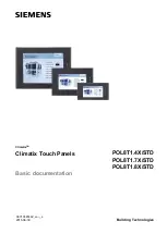
background image


Climatix

TM


Climatix Touch Panels  


POL8T1.4X/STD 
POL8T1.7X/STD 
POL8T1.8X/STD 


Basic documentation 


A6V10445442_en--_a 
2015-06-30 


Building Technologies 


Summary of Contents for Climatix POL8T1.4X/STD

Page 1: ...s Climatix TM Climatix Touch Panels POL8T1 4X STD POL8T1 7X STD POL8T1 8X STD Basic documentation A6V10445442_en _a 2015 06 30 Building Technologies ...

Page 2: ...cs Ltd Building Technologies Division No 1 Fengzhi East Road Xibeiwang Haidian District 100094 BEIJING China Tel 86 10 64768806 www siemens com buildingtechnologies 2015 Copyright by Beijing Siemens Cerberus Electronics Ltd Technical specifications subject to change without notice User interface on cover page is indicative just for marketing purpose ...

Page 3: ...connecting 13 4 1 Preparations 13 4 2 Mount the Climatix touch panel 14 4 3 Connect the Climatix touch panel 14 4 3 1 Connect power supply 15 4 3 2 Connect configuration PC 16 4 3 3 Connect Climatix controller 17 4 4 Switch on the Climatix touch panel 17 5 Operating the Climatix touch panel 18 5 1 Operate the touch screen 18 5 2 Operate the on screen keyboard 18 5 2 1 Customized keyboard 18 5 2 2 ...

Page 4: ... cable length is 2 5 m POL 0C1 45 STD 10 1 4 Before you start 1 4 1 Symbols and abbreviations This symbol marks texts that contain safety information to prevent wrong operation This symbol marks passages you should read with special care Texts marked with this symbol provide additional information notes and so on The following abbreviations are used in this document Abbreviation Explanation BSP Bo...

Page 5: ...at regular intervals Any corrections necessary are included in subsequent versions Documents are automatically amended as a consequence of modifications and corrections to the products described Please make sure that you are aware of the latest document revision date If you find lack of clarity while using this document or if you have any criticisms or suggestions please contact your local point o...

Page 6: ...ed by personnel who have been instructed by Siemens Building Technologies or their delegates and whose attention has been drawn to potential risks When wiring the system high voltage section must be strictly segregated from the DC 24V 15 safety extra low voltage SELV section in order to ensure protection against electric shock hazard Always observe the limits for storage and transport specified Th...

Page 7: ...USB interfaces for data import and export Panel mounted installation with IP65 front protection degree Communication over Modbus protocol Connection with multiple controllers Firmware upgrade by using an SD 1 card or a USB stick Graphical User Interface upgrade by using a PC and an SD card USB stick Programmable graphical interface with 3 rd party Multilanguage engineering tool Off line user inter...

Page 8: ...15 06 30 2 2 Topology The following figures show examples of the communication between the Climatix touch panel the PC and the Climatix controller Climatix POL6XX communication concept Climatix POL4XX communication concept With Climatix POL6XX controller With Climatix POL4XX controller ...

Page 9: ...s POL8T1 4X STD POL8T1 7X STD and POL8T1 8X STD The mechanical design differs for individual types A6 V1 0 44 5 44 2 M1 5 POL8T1 4X STD 4 3 No Description No Description 1 Display touch screen 6 Ethernet port 2 LED indicators 7 RS485 RS232 communication port 3 Recesses for a mounting clip 8 DIP switches 4 USB A port 9 Label 5 USB B port 10 Power supply connection ...

Page 10: ...06 30 A6 V1 0 44 5 44 2 M1 4 POL8T1 7X STD 7 No Description No Description 1 Display touch screen 6 7 RS485 RS232 communication port 2 LED indicators 8 Ethernet port 3 SD card slot 9 USB B port and DIP switches 4 Recesses for a mounting clip 10 Label 5 USB A port 11 Power supply connection ...

Page 11: ... touch screen 6 USB A port 2 SD card slot 7 8 RS485 RS232 communication port 3 LED indicators 9 USB B port and DIP switches 4 Recesses for a mounting clip 10 Label 5 Ethernet port 11 Power supply connection 2 4 Delivery scope Name Figure Quantity Touch panel 1 Power supply terminal 1 Mounting clips 4 4 3 and 7 touch panels 7 12 touch panel POL8T1 8X STD 12 ...

Page 12: ... risk of damage such as combustible gas steam or dust Do not use in environments with sharp temperature change or in high humidity Otherwise the Climatix touch panel may be damaged from internal condensation 3 3 Notes on communication The Climatix touch panel supports the following connections to an external control device RS485 RS232 connection by using a communication cable with a DB9F connector...

Page 13: ...h panel to ensure sufficient self ventilation x z x y1 y2 A6 V1 0 44 5 44 2 M 11 x y1 y2 z POL8T1 4X STD POL8T1 7X STD POL8T1 8X STD 10 10 10 10 10 10 75 25 50 20 50 20 Unit of measurement mm Avoid mounting the Climatix touch panel near other devices AC power cable controller output module relay or other electrical equipment Keep the Climatix touch panel away from equipment such as frequency conve...

Page 14: ...ting clips The maximum curvature of the mounting surface is 0 010 4 3 Connect the Climatix touch panel Workflow for connecting the Climatix touch panel 1 Connect the power supply 2 Connect the configuration PC 3 Connect the controller Field Wiring Terminal Markings Field wiring terminals shall be marked to show a range of values or a normal value of tightening torque in pound inches per the termin...

Page 15: ...such as installing a lighting arrester when placing the power supply cable in an environment subjected to lightning strikes 1 Strip the ends of three power supply cables to a length of 6 mm 2 Attach cable sleeves to the bare cable ends 3 Install the end sleeves on the cable ends using the crimp pliers 1 Insert the three power cables into the power supply terminal and secure them with a screwdriver...

Page 16: ...guration PC 1 Connect one RJ45 connector on a LAN cable to the Climatix touch panel 2 Connect the other RJ45 connector on the LAN cable to the configuration PC 3 Configure the network of the Climatix touch panel if necessary See Configure the Network Use a USB cable to connect the configuration PC The USB cable has a standard USB Type B male connector on one end 1 Connect the USB cable to the USB ...

Page 17: ... Climatix controller 1 Shut down the Climatix touch panel 2 Connect one RJ45 connector on a LAN cable to the Climatix touch panel 3 Connect the other RJ45 connector on the LAN cable to the controller 4 Configure the network of the Climatix touch panel if necessary See Configure the Network 4 4 Switch on the Climatix touch panel Switch on the power supply If the screen does not light up in two seco...

Page 18: ...e symbols on the screen of the Climatix touch panel You activate operating elements by touching them with your finger The Climatix touch panel provides a visual feedback as soon as it detects that an operating element has been touched The visual feedback is independent of any communication with the controller The visual feedback signal therefore does not necessarily indicate whether the relevant a...

Page 19: ... is enabled for the desired operating element Use the Shift key to enter upper case letters Press 123 to switch to numbers and special characters Press EN to switch input language between English and Chinese Press Done to confirm your entries 5 3 Upgrade firmware The firmware of the Climatix touch panel is upgraded by using an SD card or a USB stick Climatix touch panel is delivered with latest fi...

Page 20: ...rom the controller 5 Switch on the Climatix touch panel The Climatix touch panel displays the following color bars to indicate the upgrading is in process POL8T1 4X STD POL8T1 7X STD and POL8T1 8X STD For a USB Stick For an SD card For a USB Stick Displaying other color bars for example Red Green Blue indicates error status To solve the problem change an SD card or USB stick and try again 6 When u...

Page 21: ... by SD card or USB stick Refer to HMI TOOL online help for further information about engineering software functionalities 1 Create your GUI application with HMI TOOL 2 Download GUI application into SD card or USB stick Do not change default file name otherwise the touch panel cannot recognize it 3 Power on Climatix touch panel 4 Insert the SD card or USB stick into Climatix touch panel 5 Confirm G...

Page 22: ...ime Network configuration Serial port test Language To access Settings mode 1 Shut down the Climatix touch panel 2 Manually set the DIP switches to the position 01000 3 Switch on the Climatix touch panel All settings are stored even if the Climatix touch panel is powered off 6 1 Set screen brightness Press Brightness and adjust the brightness of display 6 2 Set the time and date Press Date time an...

Page 23: ...server on the Ethernet If Static IP is chosen enter valid values in the IP address Subnet Mask Gateway and DNS address text box 3 Press Ok to confirm The button is not functional in the current release 6 4 Test the serial ports To test the serial ports 1 Press Serial 2 Connect the desired serial port for example COM1 on the Climatix touch panel to a PC with serial port monitor software running 3 C...

Page 24: ...n setting mode enter test data for example 1234 in the Send characters textbox and press Senddata If the monitor software receives the same data 1234 in this example the test is successful 6 In monitor software enter test data and send it If the Receiving a character textbox displays the same data the test is successful 6 5 Set the language Press Language select the desired display language and pr...

Page 25: ...n cleaning wipe from the screen edge inwards Use a cleaning cloth dampened with a cleaning agent to clean the equipment Only use water with a little liquid soap or a screen cleaning sponge When cleaning the touch screen you may inadvertently trigger a response on the controller by touching keys To prevent this switch off the Climatix touch panel prior to cleaning The Climatix touch panel may be da...

Page 26: ...500 cd m 2 250 cd m 2 330 cd m 2 Active display area 4 3 16 9 7 16 9 12 1 4 3 Environmental conditions Operation Temperature Humidity Atmospheric pressure 20 50 C 10 90 RH min 700 hPa equal to max 3000 m above sea level Transport Temperature Humidity Atmospheric pressure 25 70 C 10 90 RH min 260 hPa equal to max 10 000 m above sea level Protection Degree of protection Front Rear panel In accordanc...

Page 27: ...es are not included in product package 8 2 Interface description Figure Pin Description 24V 0V Ground Figure Pin Description 1 TX 2 TX 3 RX 4 NC 5 NC 6 RX 7 NC 8 NC A standard USB interface Used for connecting to a configuration PC Figure Pin Description 1 5V DC out max 500 mA 2 Data 3 Data 4 Ground A standard USB interface Used for exporting data to a USB stick Figure Pin Description 1 5V DC out ...

Page 28: ...rs The three LED indicators are located on the front of the Climatix touch panel Marking Indicator name Color Mode Description Power supply Green On Powered on Off No power Operation Yellow On No detected fault Off CPU fault detected in the device Communication Yellow Flashing Communication in progress Off No communication 8 4 DIP switches The DIP switches are located on the back of the Climatix t...

Page 29: ...ologies Technical specifications 2015 06 30 8 5 Dimensions 173 mm 161 mm 163 mm 39 m m 85 mm 95 m m Cut out A6 V10 445 44 2M 03 153 m m 40 mm 144 m m 227 mm 208 mm 210 mm Cut out A6V1 04 45 44 2M 02 Cut out A6V1 04 454 42 M0 1 POL8T1 4X STD POL8T1 7X STD POL8T1 8X STD ...

Page 30: ...onics Ltd Building Technologies Division No 1 Fengzhi East Road Xibeiwang Haidian District 100094 BEIJING China Tel 86 10 64768806 www siemens com buildingtechnologies 2015 Copyright by Beijing Siemens Cerberus Electronics Ltd Technical specifications subject to change without notice User interface on cover page is indicative just for marketing purpose ...

Reviews: